Ph.D. Thesis
Effective Hamiltonian theory of
anomalous optical responses induced by spin-orbit interaction
スピン軌道相互作用による特異な光学応答現象 の有効理論(英文)
Hideo Kawaguchi 川口 秀雄
Department of Physics,
Graduate Scool of Science and Engineering, Tokyo Metropolitan University
首都大学東京大学院 理工学研究科 物理学専攻
2018
Abstract
Spin-orbit interaction arising from the breaking of spatial-inversion symmetry induces electromagnetic cross-correlation effects, resulting in anomalous optical responses. In present Thesis, we theoretically study anomalous light propagation induced by cross-correlation effects in spin-orbit systems by effective Hamiltonian approach based on a microscopic ground.
First, we investigate nonreciprocal directional dichroism in the magnetic Rashba conductor by deriving an effective Hamiltonian based on an imaginary-time path- integral formalism. We show that the effective Hamiltonian representing the direc- tional dichroism in the magnetic Rashba conductor is written in terms of toroidal and quadrupole moments as in insulator multiferroics. The toroidal-moment term consists of the vector coupling between toroidal moment and Poynting vector, re- sulting in the directional dichroism irrespective of the light polarization due to the Doppler shift. We also see that the quadrupole-moment term also induces directional dichroism for linearly-polarized waves. Furthermore, we discuss differ- ence between optical responses of magnetic Rashba conductor and that of 3+1 dimensional Weyl semimetal in context of the effective Hamiltonian.
Next, we examine optical properties of a Weyl spin-orbit system having quadratic dispersion by deriving an effective Hamiltonian of electromagnetic fields. We demonstrate that an optical chirality order parameter introduced by Lipkin ap- pears in the effective Hamiltonian, and that the optical chirality order parameter indeed leads to natural optical activity from the viewpoint of the effective Hamil- tonian.
Contents
Abstract i
List of Figures IV
1 Introduction 1
1.1 Electromagnetism and spintronics . . . . 1 1.2 Spin-orbit interaction . . . . 2 1.3 Electromagnetic cross-correlation effect induced by Rashba spin-
orbit interaction . . . . 3 1.4 Optical responses in Rashba conductor . . . . 5
1.4.1 Birefringence and softening of plasma frequency in non-magnetic Rashba conductor . . . . 5 1.4.2 Directional dichroism in magnetic Rashba conductor . . . . 6 1.5 Spin gauge fields . . . . 8 1.5.1 Volovik’s spin gauge field . . . . 9 1.5.2 Rashba-induced spin gauge field . . . . 11 1.6 Optical responses and cross-correlation effects in Weyl spin-orbit
system . . . . 14 1.7 Overview of this Thesis . . . . 15 2 Theory of nonreciprocal directional dichroism in magnetic Rashba
conductor 17
2.1 Phenomenological argument: Doppler-shift picture . . . . 17 2.2 Cross-correlation effects on electric permittivity . . . . 20 2.3 Derivation of effective Hamiltonian . . . . 22 2.4 Topological cross-correlation effects and optical responses in Wely
semimetal . . . . 27 3 Theory of optical activity in Weyl spin-orbit system 30 3.1 Phenomenological study: Effective Hamiltonian approach . . . . 30 3.2 Derivation of effective Hamiltonian . . . . 32
4 Conclusions 37
Appendix 37
A Edelstein Effect and inverse Edelstein Effect 38 A.1 Microscopic calculation of Edelstein effect . . . . 38 A.2 Microscopic calculation of inverse Edelstein effect . . . . 40 A.3 Microscopic calculation of Rashba-induced direct coupling effect . . 42 B Calculation of Eq. (A.28) and Eq. (A.13) 44 B.1 Calculation of Re[C(Ω)] . . . . 45 B.2 Calculation of Im[C(Ω)] . . . . 46 C Derivation of Rashba-induced spin gauge field 47 C.1 Pumped current induced by magnetization texture . . . . 47 C.2 Spin Hall current induced by Rashba-induced spin magnetic field . . 52 D Microscopic derivation of Dzyaloshinskii-Moriya interaction 55 E Partition function in path integral formalism 58
F Derivation of Eq. (2.30) 60
G Definition of coefficients g1, g2, and g3 64
H Gauge transformation 65
I Derivation of Eqs. (3.19), (3.20), and (3.21) 66
References 66
Acknowledgments 72
List of Publications 73
List of Presentation 74
List of Figures
1.1 Schematic illustration of the electron spin configuration on Fermi surface induced by the Rashba interaction. Black arrows denote the direction of the electron spin. The tangential spin configuration was optically detected in bulk Rashba conductor such as BeTeI [16]. . . 5 1.2 Schematic illustration of the directional dichroism in the magnetic
Rashba conductor. When the toroidal moment (Rashba-induced spin gauge field) AR ≡αR×M is finite, the directional dichroism is caused by the coupling between the toroidal moment and the wave vector of light. . . . . 8 1.3 Schematic illustration of ferromagnetic metals with inhomogeneous
magnetization texture. Electrons travel in the metals under the effect of the strong sd exchange interaction. . . . . 9 1.4 Schematic illustration of electron hopping. The strong sd interac-
tion changes the direction of the electron spin when the electron travels in the inhomogeneous magnetization texture. . . . 9 1.5 The Feynman diagrams for the electric current pumped by non-
uniform magnetization texture and the Rashba field. Solid lines represent the conducting electrons’ Green’s function including the sd interaction. The dotted lines and the dotted wavy lines denote the Rashba field αR and the spin gauge field As, respectively. Di- agrams (a) and (b) are contributions of j(A). Diagrams (c), (d), (e), and (f) are contributions of j(B). Diagram (g) is contribution of j(C). Note thatj(C) dose not contribute to the expression for the pumped current in this calculation. . . . 12 1.6 The Feynman diagrams for the spin Hall current driven by the
Rashba-induced spin magnetic field. Solid lines represent the con- ducting electrons’ Green’s function including the sd interaction.
The dotted lines and the wavy lines denote the Rashba interac- tion and the gauge field A, respectively. Diagrams (a), (b), and (c) are contributions of j(Hall,1). Diagrams (d) and (e) are contributions of j(Hall,2). As was pointed out in Ref. [27], the contribution arising from the spin gauge field As is negligibly small in this description.
Note that j(Hall,2) does not contribute to the expression for the Hall current in this calculation. . . . 13
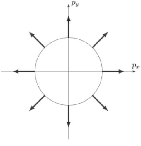
1.7 Schematic illustration of the electron spin configuration on Fermi surface induced by the Weyl interaction. Black arrows denote the direction of the electron spin. . . . . 15 2.1 The Feynman diagrams for the effective Hamiltonian. Solid lines
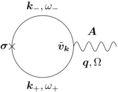
represent the conducting electrons’ Green’s function and the wavy lines denote the gauge field, respectively. Diagrams, (a), (b), (c), (d), and (e), correspond to the contributions of ne, χµνjj, χµνsj, χµνjs, and χµνss in Eq. (2.25), respectively. . . . 24 3.1 Schematic illustration of charged particle’s helical motion under the
effect ofg∇×E. Filled circle and solid arrow stand for the particle and its orbital motion, respectively. . . . 31 3.2 Diagrammatic representation of the contribution to the effective
Hamiltonian. Solid lines represent the thermal Green’s function for electron and the wavy lines denote the gauge field, respectively.
Diagrams, (a) and (b), correspond to the contributions of ne and χµνjj in Eq. (3.14), respectively. . . . 34 A.1 The Feynman diagrams for the spin density induced by Edelstein
effect. Solid lines represent the conducting electrons’ Green’s func- tion including the Rashba interaction and the wavy lines denote the gauge field, respectively. . . . 39 A.2 The Feynman diagrams for the electric current density induced by
inverse Edelstein effect. Solid lines represent the conducting elec- trons’ Green’s function including the Rashba interaction. The dot- ted and wavy lines denote the Rashba field and magnetic field, re- spectively. Note that the contribution arising from the third term on the right-hand side of Eq. (A.16) vanishes at q= 0. . . . 41 A.3 The Feynman diagrams for the electric current density arising from
Edelstein and inverse Edelstein effects. Solid lines represent the con- ducting electrons’ Green’s function including the Rashba interaction and the wavy lines denote the gauge field, respectively. Diagrams, (a) and (b) correspond to the contributions of χjjµν and ne on the right-hand side of Eq. (A.26), respectively. . . . 43 D.1 Diagrammatic representation of the contribution to the effective
Hamiltonian. Solid lines represent the thermal Green’s function including the spin-orbit and sd exchange interactions and the wavy lines denote the spin gauge field, respectively. . . . . 56
Chapter 1 Introduction
First of all, we briefly introduce electromagnetic cross-correlation effects and optical responses in spin-orbit systems without spatially-inversion symmetry in Chapter 1. Especially, we focus on effects of Rashba spin-orbit interaction and that of Weyl spin-orbit interaction in medium. We summarize the organization of this Thesis in the last section.
1.1 Electromagnetism and spintronics
Lows of electromagnetism that couple electricity to magnetism were discovered by James Clerk Maxwell and Michael Faraday about 150 years ago [1]. Conversion between electric signals and magnetic information plays an important role in the development of currently available information technologies from that time on.
Such conversions were first performed using classical laws of electromagnetism, such as Faraday’s law and Amp´ere’s law as shown below.
∇×E =−∂B
∂t , (1.1)
∇×B=µ0j+µ0ϵ0
∂E
∂t , (1.2)
where E and B are electric and magnetic fields, respectively. Here, j is the charge-current density, and ϵ0 and µ0 are the electric permittivity and magnetic permeability of the vacuum, respectively. In magnetic devices such as a cassette tape and a hard disk drive, Faraday’s law, Eq. (1.1), was used to read out in- formation while Amp´ere’s law, Eq. (1.2), is applied to write in information by magnetization flip [2].
However, these classical mechanisms have not been able to sufficiently meet the recent technological requirements of fast processing of large amounts of in- formation and high-density storage; hence, they have been gradually replaced by solid-state mechanisms such as spin-transfer torque [3, 4]. The interaction Hamil- tonian describing the spin-transfer effect in magnets is
Hst =
∫
d3rℏP
2e(1−cosθ)(j· ∇)ϕ, (1.3)
where θ and ϕ are the polar coordinates representing the direction of a magneti- zation,P is the spin polarization of conduction electrons,ℏis the Planck constant divided by 2π, and e is the electron charge. Spin-transfer torque induced by an applied electric current in ferromagnetic metals is a crucially important effect in the context of current-induced magnetization reversal in spintronics. In fact, we see that the spin torque by the electric current, τst ≡ −δHδnst =−2eP(j ·∇)n, acts on a magnetization, wherenis a unit vector representing the direction of the mag- netization; hence the magnetization reversal can be induced by the spin-polarized electric current (spin current) described as js ≡Pj. The idea of the spin-transfer effect was first proposed theoretically by Berger [5] in the case of a domain wall motion and by Slonczewski [3] and Berger [4] in the case of the uniform mag- netization of thin films. The spin-transfer effect arises from the transfer of spin angular momentum from conduction electrons to localized spins which induce the magnetization. The effect is caused by ansdexchange interaction, and the angular momentum transfer occurs owing to the angular momentum conservation [3].
In resent years, the effect arising from spin-orbit interaction attracts the in- terest of researchers in this context. One example is the magnetization reversal using an effective magnetic field induced by a spin-orbit interaction, called Rashba interaction (Ref. [6]). In the case of a strong sd interaction, i.e., adiabatic limit, the interaction describing the magnetization reversal is given by [7–10]
Hst,R =−
∫
d3r(Beff,R·n), (1.4)
with
Beff,R ≡ m
eℏ(αR×js), (1.5)
where m is electron mass and αR is the Rashba field along z-axis representing the strength of the Rashba interaction. It was reported that the effective magnetic field induced by the Rashba interaction such as Eq. (1.5) plays a key role in pining for domain wall motion under the electric current [11]. Refs. [12, 13] have been argued optical magnetization reversal induced by inverse Faraday effect, which is a nonlinear effect with respect to an incident electric field in the presence of the Rashba interaction.
1.2 Spin-orbit interaction
Spin-orbit interaction, which couples the orbital motion of an electron to its spin via a relativistic effect, plays an important role in the context of a mixing of electric and magnetic degrees of freedom. Originally, spin-orbit interaction is derived directly from the Dirac equation as a relativistic effect [14]. Under the effect of electromagnetic fields, the Dirac equation is given by
[∑
µ
γµ (
i ∂
∂xµ −q cAµ
)
−mc ]
ψ = 0, (1.6)
where we set ℏ = 1, γµ is gamma matrices, c is light speed, m is rest mass of Dirac electron, q is the charge of Dirac electron, and ψ is the Dirac field having 4-components. Here, Aµ ≡ (ϕ,A) is a gauge field being 4-vector whose time component is a scalar potential and whose spatial component is a vector potential.
Using the 4×4 matrices, αi ≡γ0γi and β≡γ0, Eq. (1.6) reads i∂
∂tψ =HDiracψ, (1.7)
with
HDirac ≡ [
cα·( p− q
cA )
+mc2β+qϕ ]
, (1.8)
where p ≡ −i∇ is a linear momentum of Dirac electron and HDirac is the Dirac Hamiltonian being 4×4. In non-relativistic limit, Eq. (1.8) up to the second order inp reduces to the 2×2 Hamiltonian such as
H ≃ p2
2m −qϕ− q
2mc(B·σ)− q
16m2c2(∇·E) +HSOI, (1.9) with
HSOI ≡ −λsoE·(p×σ), (1.10) whereσis the vector of Pauli matrices,λso ≡ 4mq2c2 andE ≡ −∇ϕandB≡∇×A are electric and magnetic fields, respectively. In Eq. (1.9), the first term is kinetic energy of the charged particle. The second term is the interaction between the particle charge and the scalar potential. The third term is Zeeman interaction describing the coupling between the magnetic field and the particle’s spin. The fourth term is called Darwin term. The term HSOI is spin-orbit interaction that couples particle motion to it’s spin andλsois the coupling constant of the spin-orbit interaction in vacuum.
1.3 Electromagnetic cross-correlation effect in- duced by Rashba spin-orbit interaction
Recent studies have shown that spin-orbit interaction becomes prominent for surfaces and interfaces containing heavy metals as it significantly modifies their electric and magnetic properties as a consequence of inversion symmetry breaking [15]. The most typical spin-orbit interaction lacking inversion symmetry is the Rashba interaction [6], whose Hamiltonian is as shown below.
HR =−αR·(p×σ), (1.11)
where p is a linear momentum of electron, σ is the vector of Pauli matrices, and αR is the Rashba field representing the strength and direction of the Rashba spin-orbit interaction. This form of interaction is derived directly from the Dirac
equation as a relativistic effect as was shown in section 1.2, but its magnitude can be significantly enhanced for solids containing heavy elements as compared to that for the vacuum case.
Of particular current interest is electromagnetic effects induced by such strong spin-orbit interaction because the effects are qualitatively different from conven- tional electromagnetic responses like in Ohm’s law and Curie’s law as shown below.
j =σBE,
M =χB, (1.12)
wherej is an electric current,M is a magnetization,σBis the Boltzmann conduc- tivity, and χ is the magnetic susceptibility. A direct consequence of the Rashba interaction is electromagnetic cross-correlation effects where a magnetization and an electric current are induced by external electric and magnetic fields, E and B, as
ME=γM E(αR×E), (1.13)
jIE =γjB(αR×B), (1.14)
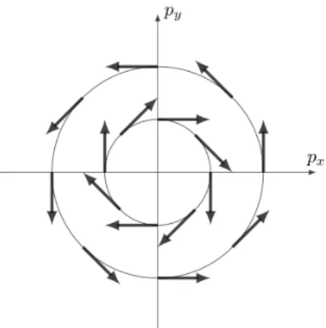
where γM E and γjB are coefficients that generally depend on frequency. The Rashba field induces a tangential electron spin texture on Fermi surface depicted in Fig. 1.1, resulting in effects described by Eqs. (1.13) and (1.14). The emer- gence of spin accumulation from the applied electric field, mentioned in Ref. [6], was studied in detail by Edelstein [17]; hence, this effect is sometimes referred to as the Edelstein effect. Experimentally, the magnetization by Edelstein effect is observed using Kerr effect at interface between Cu, Ag and Bismuth oxide [18].
The generation of electric current by a magnetic field or magnetization, called the inverse Edelstein effect [19], was recently observed in a multilayer structure consisting of Ag, Bi, and a ferromagnet [20]. In Appendixes A.1 and A.2, we confirm that the the Edelstein and inverse Edelstein effects arise from the spin polarization induced by Rashba interaction through the microscopic calculation in the long-wave region [21, 22].
Figure 1.1: Schematic illustration of the electron spin configuration on Fermi sur- face induced by the Rashba interaction. Black arrows denote the direction of the electron spin. The tangential spin configuration was optically detected in bulk Rashba conductor such as BeTeI [16].
1.4 Optical responses in Rashba conductor
1.4.1 Birefringence and softening of plasma frequency in non-magnetic Rashba conductor
Recent studies (Refs. [21, 22]) showed that the cross-correlation effects of the Rashba spin-orbit interaction lead to anomalous optical properties in bulk Rashba conductor. From Eqs. (1.13), we obtain a magnetization current induced by the Edelstein effect as
jE≡∇×ME
=iγM E[(αR·k)E−(k·E)αR], (1.15) wherekis the wave vector of electromagnetic waves. Using Faraday’s law (∇×E=
−∂B∂t) and the Onsager’s reciplocal relation (γjB = iωγM E, where ω is angular frequency of electromagnetic waves), Eq. (1.14) is rewritten as
jIE =iγM E[(αR·E)k−(αR·k)E]. (1.16) We thus get the electric current including the cross-correlation effects as
jEE−IE,µ ≡jE,µ+jIE,µ =∑
ν
σµνEE−IEEν, (1.17) with
σEEµν−IE(ω) =iγM E(kµαR,ν−αR,µkν), (1.18) where σµνEE−IE is an electric conductivity tensor being liner in k. Above equation indicates that Edelstein and inverse Edelstein effects give rise to an antisymmetric
component of the electric conductivity tensor, resulting in an anomalous optical response for linearly-polarized waves such as birefringence [21, 22]. In fact, from Maxwell’s equations and Eq. (1.18), we obtain the dispersion relation of light describing extraordinary waves where the direction of Poynting vector and that of the wave vector differ,
k =ω [
c2−
(γM EαR ϵ0
)2]−1
2
, (1.19)
wherec is the light velocity in vacuum.
Furthermore, it was pointed out that a strongly anisotropic light propagation arises from the electric current induced by a direct coupling between Edelstein effect and inverse Edelstein effect defined as
jEIE≡γM E(αR×ME). (1.20) The anisotropic contribution arising from the Rashba field is written by diago- nal components of the electric conductivity tensor as shown below [21, 22]. (see Appendix A.3 for details of the derivation.)
σµνEIE(ω) = ie2 ω+i0
ne m [
δµν[1 +C(ω)]−αˆR,µαˆR,νC(ω) ]
, (1.21)
where ˆαR ≡ αR/|αR| is a unit vector representing the direction of the Rashba field, 0 is a positive infinitesimal, and ne and C(ω) are defined in Eq. (A.28) and Eq. (A.13), respectively. Equation (1.21) leads to the softening of plasma frequency due to C(ω) originated from the current-spin correlation function. As a consequence of the softening of plasma frequency, the dispersion relation being hyperbola for linearly-polarized waves,
ω2
c2 = k2x
1 +ϵEIEzz + kz2
1 +ϵEIExx , (1.22)
can emerge, resulting in a hyperbolic metamaterial [23] that exhibits a negative refraction and a focusing effect, where ϵEIExx = −ωω2p2[1 +C(ω)], ϵEIEzz = −ωωp22, and ωp ≡√
e2n2e
ϵ0m is the plasma frequency. Here, we used the relation,ϵµν =δµν+iϵ1
0ωσµν.
1.4.2 Directional dichroism in magnetic Rashba conductor
Until now, we introduce electromagnetic cross-correlation effects and optical responses in the Rshaba system with time-reversal inversion. Refs. [21, 22] also re- ported anomalous optical responses in magnetic Rashba conductors realized in the Rashba system attached ferromagnet. In such systems, the time-reversal invari- ance breaking is caused by the sd exchange interaction that couples the electron spin to the magnetization, whose Hamiltonian is given by
Hsd =−Jsd
∫
d3r(M ·σ), (1.23)
where, M is the magnetization vector, σ is the vector of Pauli matrices, and Jsd is the strength of the exchange interaction.
If Rashba conductors are magnetic or under the effect of an external mag- netic field, directional dichroism, a form of anisotropic wave propagation, has been shown to occur as with insulator multiferroics. An electric conductivity tensor de- scribing optical responses in magnetic Rashba conductors is given by [21, 22]
σµνM(Ω) =σAHE(Ω)∑
l
ϵµνlMk∥
+σ1M(Ω)(αR×M)·q[δµν −αˆR,µαˆR,ν] +σ2M(Ω)[(αR×M)µqν⊥+ (αR×M)νq⊥µ] +σ3M(Ω)∑
ℓm
[Mµ⊥αR,ℓϵνℓm+ϵµℓmMν⊥αR,ℓ]qm, (1.24) whereqand Ω are the wave vector and angular frequency of electromagnetic waves, respectively, q⊥≡q−αˆR( ˆαR·q),M∥ ≡(αR·M)αR, M⊥ ≡M−αˆR( ˆαR·M), ϵµνl is a totally antisymmetric tensor, and σAHE, σM1 ,σ2M, and σ3M are coefficients depending on the angular frequency. The antisymmetric component beingq0 with σAHE on the right-hand side of Eq. (1.24) induces anomalous Hall effect [24] when αR·M is finite, resulting in the magneto-optical effect such as Faraday effect [25]
for circularly-polarized waves traveling along in the direction of magnetization.
The dispersion relation describing the Faraday effect is q2 = Ω2
c2 [
1± σAHE(Ω)αR2(−M) ϵ0Ω
]
, (1.25)
where ± stands for the sense of circular polarization. On the other hand, the symmetric terms proportional to q1 on the right-hand side of Eq. (1.24) lead to diagonal components, resulting in directional dichroism depending on the direction of light propagation in the case where αR×M being finite andq take parallel or antiparallel configuration. In fact, the dispersion relation describing the directional dichroism for linearly-polarized waves is shown to be [21, 22]
q =Ω c
√1 +ϵEIExx +σ13M(Ω)[(αR×M)·q],ˆ (1.26)
whereσ13M ≡σ1M +σM3 .
The directional dichroism was found to be governed by the relative direction of the wave vector and another vector AR ≡ αR×M depicted in Fig. 1.2. The latter vector is known to be an effective gauge field coupled with the electron’s spin (Rashba-induced spin gauge field), which generates a spin current [26–28]. From the symmetry point of view, the Rashba fieldαR is equivalent to an electric polar- izationP (Ref. [29]); hence, the vectorARworks as a toroidal momentt ≡P×M. The toroidal moment has been reported to act as an effective vector potential for light in the case of multiferroics [30]; however, microscopic justification for the same has not been provided. The study in Refs. [21, 22] further discussed that the effective theory describing magnetic Rashba conductors is similar to the one describing insulator multiferroics.
In Chapter 2, we examine the propagation of electromagnetic waves in mag- netic Rashba conductors based on an effective Hamiltonian analysis on a micro- scopic ground. We show that the effective Hamiltonian describing the directional dichroism consists of two terms, one representing the Doppler shift and the other denoting the cross-correlation effect induced by a quadrupole moment [31]. The results of our study confirm with those of Refs. [21, 22] obtained by calculating an optical conductivity.
Figure 1.2: Schematic illustration of the directional dichroism in the magnetic Rashba conductor. When the toroidal moment (Rashba-induced spin gauge field) AR ≡αR×M is finite, the directional dichroism is caused by the coupling between the toroidal moment and the wave vector of light.
1.5 Spin gauge fields
In this section, we introduce two spin gauge fields. First one is the Volovik’s spin gauge field, and second one is the Rashba-induced spin gauge field which plays an important part in argument about the directional dichroism in magnetic Rashba conductors. Rewriting the spin-transfer interactions shown in Sec. 1.1 in terms of the spin gauge fields, we see that these fields generate the spin current.
1.5.1 Volovik’s spin gauge field
Figure 1.3: Schematic illustration of ferromagnetic metals with inhomogeneous magnetization texture. Electrons travel in the metals under the effect of the strong sd exchange interaction.
In ferromagnetic metals without the Rashba interaction depicted in Fig 1.3, an effective electromagnetic field arises from thesdexchange interaction described by
Hsd =−∆sd
∫
d3r(n·se), (1.27)
where ∆sd ≡JsdM is the exchange energy,M ≡ |M|,nis a unit vector represent- ing the direction of the magnetization, and se is the direction of the conduction electron spin. When this exchange interaction is strong, the conduction electron spin is aligned parallel to the magnetization direction, and this effect results in a quantum mechanical phase attached to the electron spin when the electron moves (see Ref. [32] for details of derivation). The spin part of the electron wave function with the expectation value alongn≡n(r) is|n⟩= cosθ2| ↑⟩+ sinθ2eiϕ| ↓⟩, wherer means a position,θ and ϕ are the polar coordinates of n, and| ↑⟩ and | ↓⟩denote the spin states [33].
Figure 1.4: Schematic illustration of electron hopping. The strong sd interac- tion changes the direction of the electron spin when the electron travels in the inhomogeneous magnetization texture.
When the electron hops over a small distance dr ≡ r′ −r to a nearby site where the magnetization is along n′ ≡ n(r′) as is shown in Fig. 1.4, the overlap
of the wave functions is calculated as ⟨n′|n⟩ ≃eℏieAzs·dr, where Azs = ℏ
2e(1−cosθ)∇ϕ, (1.28)
and the factor of 12 is due to the magnitude of the electron spin. The field Azs is an effective vector potential or an effective gauge field. When the electron’s path is finite, the phase becomes φ= eℏ∫
Cdr ·Azs. The existence of the phase means that there is an effective magnetic field Bs, as seen by rewriting the integral over a closed path using the Stokes theorem as φ= eℏ∫
SdS·Bs, where Bs ≡∇×Azs. The time derivative of the phase is equivalent to a voltage, and thus, we have an effective electric field defined by ˙φ = −eℏ∫
Cdr ·Es, where Es ≡ −A˙zs. These two fields satisfy Faraday’s law, ∇×Es+ ˙Bs = 0. We therefore have effective electromagnetic fields that couple to the conduction electron spin as a result of the sd exchange interaction. We call the field a spin electromagnetic field [34]. Using the explicit form of the effective gauge field, Eq. (1.28), we see that the emergent spin electromagnetic fields are
Es,i = − ℏ
2en·( ˙n× ∇in), Bs,i = ℏ
4e
∑
jk
ϵijkn·(∇jn× ∇kn). (1.29) The magnetic componentBs is the spin Berry’s curvature [35] or scalar chiral- ity. The electric component Es, called the spin motive force, is a chirality in the space-time, which arises when the magnetization structure n is time-dependent.
The expression Eq. (1.29) was derived by Volovik in 1987 [36]. Experimentally, the spin magnetic field (the spin Berry’s curvature) has been observed using the anomalous Hall effect 1 in frustrated ferromagnets [37, 38]. The spin electric field has been measured in the motion of various ferromagnetic structures such as do- main walls [41], magnetic vortices [42], and skyrmions [43].
By use of Eq. (1.28), we see that the spin-transfer interaction, Eq. (1.3), is represented as a gauge coupling to the adiabatic spin gauge field (Volovik’s spin gauge field) (Refs [2, 44]) as shown below.
Hst =
∫
d3r(js·Azs), (1.30) wherejsis the spin-polarized electric current. Above expression clearly shows that the adiabatic spin gauge field Azs induces the spin current. In the case of the sd interaction having time dependence, it is theoretically shown that non-adiabatic components of an SU(2) spin gauge field intrinsically contribute to the spin current generation in the context of the spin pumping effect [45].
1By taking into consideration of vertex corrections due to random impurities, the anomalous Hall effect induced by the non-local component of the scalar chirality is theoretically investigated in the case of a weaksdinteraction [39, 40].
1.5.2 Rashba-induced spin gauge field
In Ref. [27], the Rashba-induced spin gauge field is derived in the strong sd coupling region by calculating a pumped electric current,jpump, by magnetization texture and a spin Hall current, jHall, by effective magnetic field based on the microscopic transport theory [28, 46]. These electric currents are given by (see Appendixes C.1 and C.2 for details of derivation)
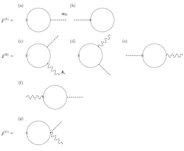
jpump =j(A)+j(B)+j(C)
=−a1 ∂
∂t(αR×n) +b1∇×[∇×(αR×n)], (1.31) jHall =j(Hall,1)+j(Hall,2)
=−c1E×[∇×(αR×n)], (1.32)
where n is a unit vector representing the direction of the magnetization. Con- tributions for jpump and jHall at the linear order of the Rashba interaction are diagrammatically shown in Fig. 1.5 and Fig. 1.6, respectively. The coefficientsa1, b2, and c3 are defined in Appendixes C.1 and C.2.
From Eq. (1.31), Eq. (1.32), and Maxwell’s equation including effective spin electromagnetic fields in medium (Refs. [28, 46]),
j =σsEs,eff + 1
µs∇×Bs,eff, (1.33)
with the spin-dependent electric conductivityσs and the spin-dependent magnetic permeability µs, Rashba-induced spin electric and magnetic fields are obtained as
ER ≡ −A˙R =−αR×n˙
BR ≡∇×AR =∇×(αR×n), (1.34)
respectively. These two fields satisfy Faraday’s law, ∇×ER+ ˙BR = 0. Here,
AR ≡αR ×n (1.35)
is the Rashba-induced spin gauge fields [27], which is an effective vector potential for electron spin. The spin-dependent electric conductivity, magnetic permeability, and Hall conductivity are given by a1, b−11, and c1, respectively. Using the above expression, the spin-transfer interaction by the Rashba interaction, Eq. (1.4), is rewritten as a form of gauge coupling as shown below.
Hst,R =
∫
d3rm
e (js·AR). (1.36)
Therefore, we see that the Rashba-induced spin gauge fields AR plays a role of the spin current generation as with the adiabatic spin gauge field suggested by Volovik.
Figure 1.5: The Feynman diagrams for the electric current pumped by non-uniform magnetization texture and the Rashba field. Solid lines represent the conducting electrons’ Green’s function including the sd interaction. The dotted lines and the dotted wavy lines denote the Rashba field αR and the spin gauge field As, respectively. Diagrams (a) and (b) are contributions of j(A). Diagrams (c), (d), (e), and (f) are contributions of j(B). Diagram (g) is contribution of j(C). Note that j(C) dose not contribute to the expression for the pumped current in this calculation.
Figure 1.6: The Feynman diagrams for the spin Hall current driven by the Rashba- induced spin magnetic field. Solid lines represent the conducting electrons’ Green’s function including the sd interaction. The dotted lines and the wavy lines denote the Rashba interaction and the gauge fieldA, respectively. Diagrams (a), (b), and (c) are contributions ofj(Hall,1). Diagrams (d) and (e) are contributions ofj(Hall,2). As was pointed out in Ref. [27], the contribution arising from the spin gauge field As is negligibly small in this description. Note thatj(Hall,2) does not contribute to the expression for the Hall current in this calculation.
As has been reported by Volovik [36], the original spin gauge field (adiabatic spin gauge field) occurs in the absence of the Rashba interaction in the strong sd-coupling regime (Ref. [32]), and induces effective electric and magnetic fields acting on electron spin as was shown in Sec. 1.5.1. Originally, the emergence of the effective electric field from moving magnetic structures was found in 1986 by Berger, where a voltage generated by canting a moving domain wall was calculated [5]. Stern discussed the motive force in the context of the spin Berry’s phase and the Aharonov-Bohm effect in a ring, and showed similarity to Faraday’s law [47].
The spin motive force was rederived in Ref. [48] in the case of the domain wall motion, and discussed in the context of topological pumping in Ref. [49]. Recenty, a generation mechanism of a spin electric field using a nonlinear effect of non- monochromatic spin-wave excitations was proposed in Ref. [50]. This mechanism is applicable to the case of a uniform magnetization, and it would have a great advantage in applications over common setups using non-coplanar structures. This theoretical considerations call for an experimental verification of the effect. The coupling of adiabatic spin gauge field to electromagnetic field was studied based on the effective Hamiltonian study in Refs. [50,51]. It was found that the spin-transfer effect is described using the linear coupling term of the adiabatic spin gauge field and the electric field2. Ref. [54] reported the effect of adiabatic spin gauge field on
2It was experimentally confirmed that the spin-transfer effect causes nonreciprocal spin-wave propagation due to the Doppler shift in ferromagnetic metals when the electric current is applied [52]. Recent study (Ref. [53]) theoretically showed that the spin-transfer effect can induce the