令和元年度
博士後期学位論文
Multi-objective optimization design of
electric-vehicle frame based on topology
CONTENTS
Abstract ...I
Chapter 1 Introduction ... 1
1.1 Background ... 2
1.2 Research Status of Structure Optimization on Electric Vehicle Frame ... 6
1.3 Research Status of Automotive Frame Lightweight ... 8
1.3.1 Lightweight design and optimization ... 9
1.3.2 Automotive lightweight materials ... 10
1.4 Purpose of this research ... 17
References ... 21
Chapter 2 Multi-objective topology optimization theory ... 30
2.1 Data model for topology optimization design ... 31
2.2 Methods for topology optimization ... 32
2.2.1 Homogenization method ... 34
2.2.2 Variable thickness method ... 35
2.2.3 Variable density method ... 35
2.3 Multi-objective topology optimization ... 37
2.3.1 Multi-case topology optimization objective function ... 38
2.3.2 Quality topology optimization objective function ... 39
2.3.3 Multi-objective topology optimization function considering both strength and quality requirements ... 40
2.4 Frame collision safety evaluation theory ... 41
2.5 Concluding remarks ... 44
References ... 45
3.1 Establishment of finite element model for frame ... 50
3.1.1 Initial geometric model establishment of frame topology optimization . 51 3.1.3 Determine working load and constraints ... 53
3.2 Acquire material properties ... 54
3.2.1 Tensile test ... 54
3.2.2 Damping test ... 58
3.3 Analysis of Static Strength of Frame Structure ... 60
3.4 Concluding remarks ... 67
References ... 68
Chapter 4 Frame collision impact analysis ... 70
4.1 Dynamic Impact Optimization Theory ... 71
4.1.1 Dynamic response principle ... 72
4.1.2 Relationship between structural damping and stiffness ... 74
4.1.3 Collision theory of frame ... 76
4.2 Frame Modal Experiment and Verification ... 78
4.3 Frame dynamic impact analysis and optimization ... 81
4.4 SAIKO-frame simulated actual collision analysis ... 88
4.5 Conclusions ... 95
References ... 96
Chapter 5 Conclusions and Innovation ... 98
5.1 Conclusions ... 99
5.2 Innovation ... 100
Related publications ... 101
Abstract
With the development of the automobile industry, the crisis of energy and environment has made the national governments accelerate the strict control of energy consumption and emissions from the automotive industry. Automobile lightweight design has become an important development direction of the automotive industry. The future direction of automotive lightweight includes the systematic design and integration of optimized design methods for automotive structural parts, multi-material integration, and lightweight technologies. The application of new lightweight materials is the key to automotive lightweight technology. On the basis of ensuring the comprehensive performance of components, the optimization of new material structures through topology optimization methods can further improve the level of lightweight components.
As an important load-bearing component of electric vehicles, electric vehicle frame is essential for the safety and comprehensive performance of the whole vehicle. As a forward-looking lightweight material, magnesium alloy materials have gradually gained wider applications in automobiles. To realize the in-depth application of magnesium alloy materials on automobile frames, it is of great theoretical significance to carry out research on the important performance prediction of the frame made of magnesium alloy materials.
Firstly, taking the electric vehicle frame as the research object, the finite element model of the electric vehicle steel frame is established, and the modal experimental design of the steel frame is carried out to verify the correctness of the frame finite element model.
and static load of the electric vehicle frame to establish the static strength analysis model of the magnesium alloy frame. The mechanical parameters of the magnesium alloy material are obtained through the mechanical properties test of the magnesium alloy material for carrying out the static strength of the magnesium alloy frame; the static strength analysis results of the steel frame are taken as the goal, and the structural strength optimization design of the magnesium alloy frame is carried out based on the topology optimization design method, and the weight of the frame is realized on the basis of ensuring the strength of the magnesium alloy frame.
1.1 Background
The demand for the automotive market continues to expand, and the demand for automobiles in the global market will continue to grow rapidly, both now and in the next few decades. Although the demand for trucks in the more developed areas along the eastern coast of China is close to saturation, the demand for medium and heavy-duty trucks, work vehicles and special vehicles in the sub-developed areas is still very large. And with the cooperation between China's auto industry and countries around the world, the demand for various trucks, special vehicles and large and medium-sized buses in Africa and South America is still very large. With the development of the expressway network, the semi-trailer has become one of the important models in the current logistics market due to its advantages of good safety and high transportation efficiency. In addition, China’s relevant policies attach importance to the transportation mode, making the semi-trailer prospects are bright. As a power source for semi-trailers, the development of tractors is highly valued by commercial vehicle companies. As the main bearing component of the tractor, the frame, the powertrain, the fuel tank, and many other components are mounted on it, and the frame is used to ensure the correct relative position, which plays the role of the vehicle "skeleton". It must have good performance, so whether it is possible to design a frame with good mechanical properties, lightweight and low manufacturing cost is particularly important for the performance of the entire car.
of the effective ways to achieve energy-saving and emission reduction. In order to reduce the automobile weight, aluminum alloy, high strength steel, magnesium, composite material, and so on, are widely used as light-weighting materials to replace the traditional material of mild steel [2,3]. Magnesium, which is considered the best alloy in the 21st century, is the lightest structural metal and has good material damping properties, high specific strength, and stiffness [4-7]. Because of these advantages over other metals, the application of magnesium alloys is substantially increasing. Magnesium average usage and projected usage growth per car are given as 20 kg, 50kg, and 60kg for 2010,2015 and 2020, respectively [8-12].
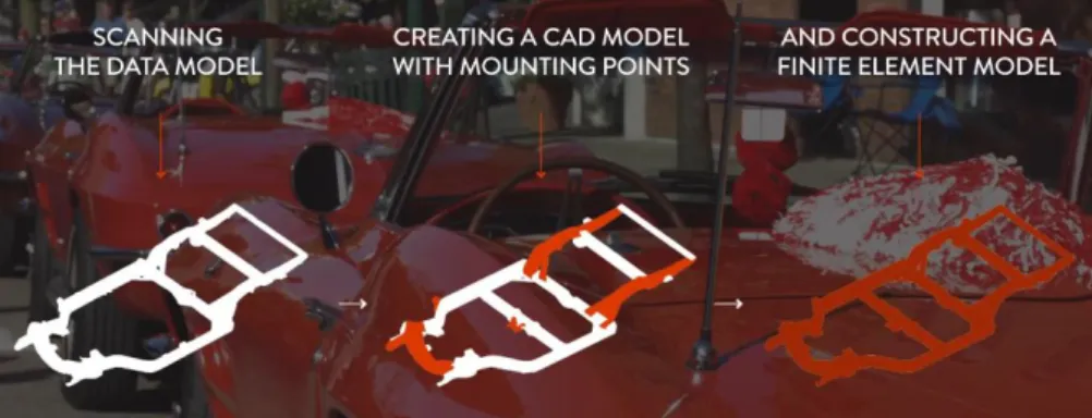
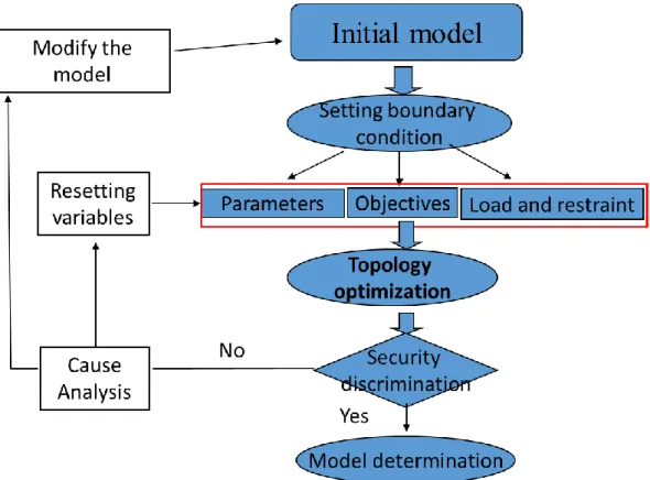
For the design of the frame, the traditional design method is to first complete the CAD modeling, and then through the CAE analysis, if the requirements are not met during the CAE analysis process, the model needs to be modified until the CAD modeling passes the requirements of the CAE analysis, and then the sample is processed. Test, if not, you need to re-design the CAD. In this design process, the initial model of the frame is designed and processed by experience, and then the performance verification is carried out, which not only has a long cycle, high cost, but also cant find the frame structure with the most reasonable material distribution, resulting in high fuel
consumption and low carrying capacity. This obviously cannot adapt to the increasingly fierce competitive market. Today's enterprises need to continuously improve their research and development capabilities and production efficiency. Whether to shorten the research and development cycle, improve vehicle performance and reduce production costs at the same time determines the future viability of vehicle enterprises. The rapid development of computer technology has provided a new design method for the development of automobiles. The CAD/CAE (Computer-Aided Design/Computer-Aided Engineering) technology combined with computer technology and numerical calculation method has become the automobile of today's automobile personnel. The mainstream approach to R&D can quickly and accurately solve engineering problems. Applying CAD/CAE technology can reduce the development cycle of new vehicles from 5 years to 24 to 26 months. Today, the application of CAE technology in the automotive product development process has been used as a key indicator to reflect a company's automotive R&D level. After decades of development and improvement, CAE is very mature, widely used in the fields of mechanics and engineering science, and almost all problems related to continuous media and fields can be solved.
large forces of impact. This produces contact forces and friction between these parts. Studying the new lightweight method and new technology of electric vehicle frame structure is one of the butler techniques to improve the research and development level of automobile product structure and improve the independent innovation ability. The design process of the product structure is essentially an optimization process that seeks to ensure that the vehicle structure and its components meet certain economic and performance indicators. This optimized design process is also an iterative design process.
1.2 Research Status of Structure Optimization on Electric
Vehicle Frame
The lightweight structure of the car body is mainly concentrated in two aspects, one is based on improving the fuel economy of the car, and the other is based on improving the performance and safety of the car. The main research methods can be divided into the following parties.
1. Optimize the structure through modern design methods to obtain a new lightweight structure.
2. Taking advantage of the hardware, a large number of constraints in dynamic processes (such as collisions, vibrations) are considered, and the size parameters are optimized to obtain a lightweight structure, but safety is emphasized.
3. Apply modern optimization algorithms (such as genetic algorithm, artificial neural network algorithm) to the lightweight design of the structure.
In 1994, the American Iron and Steel Association and the International Iron and Steel Association jointly launched the ULSAB (Ultra Light Steel Auto Body) project, whose main purpose is to improve the strength and rigidity of steel, thereby effectively reducing the quality of the car body, saving materials and reducing the vehicle. Self-weight. The results of the program are remarkable: ULSAB's total body quality is reduced by 25% compared to conventional vehicles, torsional stiffness is increased by 80%, bending stiffness is increased by 52%, first-order modal frequency is increased by 58%, and collision safety requirements are fully met. And the cost is reduced by 15%。
1.3 Research Status of Automotive Frame Lightweight
A modern lightweight vehicle frame has been developed for builders of replica classic cars. The frame is comprised of aluminum, magnesium, carbon fiber and advanced high strength steel.
It matches the body frame of the 1963-1967 Corvette, also known as C2, for second-generation Corvette design. With the alternate materials, the new frame is about one-third lighter than the original as well as being stiffer.
Lightweight, which is on the premise of meeting the requirements of automobile finishing and use, to minimize the quality of each component and achieve the optimal combination of quality-performance-cost. When designing lightweight automotive structures, three requirements must be considered: one is the strength requirement, which cannot cause material damage; the other is the stiffness requirement, that is, the deformation cannot exceed the allowed range; the third is the stability requirement, including dynamic stability and static stability. Lightweight technology covers many industries and disciplines, and the industry chain is long. The main processes are product lightweight design, material lightweight selection, process processing to obtain lightweight results, product testing, and product life cycle assessment.
There are three main ways to achieve automotive lightweight: first, to improve the structure of the car, to make parts thinner, hollower, miniaturized, and composited; and to develop new lightweight materials, such as the use of nonferrous metals such as aluminum and magnesium alloys, plastics, and Non-metal composite materials, or high-strength steels with thinner sections; the third is the use of advanced manufacturing processes, such as laser tailor welding, hydraulic forming, and roll forming.
save materials on the one hand; more importantly, it can effectively save energy, thereby reducing exhaust emissions.
The frame also eliminated the welding process for assembly, principal materials engineer for the Michigan Manufacturing Technology Center (Plymouth, MI), which showed the frame at SAE International’s World Congress Experience (WCX) event in Detroit. Instead of welding, adhesives and through-bolts were used to assemble the frame. “You don’t need a skilled welder so we can use lower-cost labor,” Peterson said. The technology center developed the frame along with Lightweight Innovations for Tomorrow (LIFT; Detroit), Institute for Advanced Composites Manufacturing Innovation (IACMI; Knoxville, TN) and the University of Tennessee.
1.3.1 Lightweight design and optimization
CAE, a computer-aided engineering simulation tool, is playing an increasingly important role in the design of body and parts. It can shorten the research and development cycle and improve the weight reduction effect. It has become an indispensable important method for the development of new energy vehicles. In fact, lightweight structural design is based on the conceptual model of the original structure to make the distribution of materials (often multi-material systems) more reasonable and remove materials that are not involved in the force. Now commonly used is the topology optimization solution method.
In the early stages of conceptual design, the goals of structural optimization can be subdivided into topology optimization, shape optimization, and size optimization, as shown in Fig 1.2. Topology optimization refers to determining the optimal material distribution and connection of the structure by software under the given design space, constraints, load conditions, and specific process requirements; the method of topology optimization is applied in the initial stage of product design and uses optimization Calculate to obtain the structural material distribution that meets the design requirements. Shape optimization is the detailed structural design of the body with the determined topology after the topology optimization, and the structural shape of the most material-saving is analyzed in the structural design. Finally, according to the established topology and structure shape, the main dimensions of the structure are optimized to meet the requirements of strength, stiffness, and stability. So far, structural optimization cannot be separated from the finite element simulation analysis method. Many existing finite element software can support topology optimization, size optimization, and shape optimization. The representative is the obstruct module in her work, which has been designed by manufacturing companies. Some software has even implemented the parametric design of geometric models and grids, such as SFE Concept, is optimum software. At present, the domestic SAIC Research Institute and Pan Asia Technology Center have carried out research on parametric design [13-20].
1.3.2 Automotive lightweight materials
Lightweight materials for automobile bodies are mainly steel, aluminum, magnesium, titanium, cast iron and non-metallic materials, of which steel is the most widely used.
1. High-strength steel material
High-strength steels (yield High-strength greater than 210Mpa) and ultra-high-High-strength steels (yield strength greater than 550Mpa) have been developed. When the thickness of the steel plate is reduced by 0.05m, 0.1mm, and 0.15mn, the body weight is reduced by 6%, 12%, and 18%, respectively. The use of high-strength steel plates can not only improve the lightweight of the car, but also significantly improve the bending rigidity and torsional rigidity of the car body. The amount of high-strength steel plates in mid-to-high-end passenger cars has reached 20% -50% of the steel plate consumption.
In terms of new steel development, foreign steel companies have invested a lot of money in the Ultra-Light Stele Auto Body (ULSAB) project, Ultra-Light Stele Auto Closures (ALS) A, Ultra-Light Stele Auto Body-advanced Vehicle (Concepts), etc. Researching and developing a new generation of steel materials as a whole has significantly improved the bending and torsional stiffness of steel materials. South Korean media reported that South Korea’s Pohang University of Technology has successfully developed a new alloy material that is lightweight, low-priced, and stronger than titanium.
steel and Q & P steel.
2. Aluminum alloy material
Aluminum alloy is currently the most used light metal material. The density of pure aluminum is 2.68g / cm3, and the density is about 1/3 of steel. A single piece can be about 50% lighter, with high strength, good corrosion resistance and weather resistance. At present, the application of aluminum in the body is not limited to a single part, and models with all-aluminum bodies or all-aluminum chassis have appeared on the market. The Audi A8 was the first overall winner. Its 93.1% aluminum alloy body structure design makes its body weight reach 231k (including the door cover is 3007kg), the torsional stiffness is 37600Nm / deg, and the weight reduction coefficient reaches 1.2. At present, the research on aluminum alloy of automobile body mainly focuses on two square paintings. On the one hand, it is the study of aluminum alloy itself. The mechanical properties of aluminum alloy are changed by adding some alloy elements. On the other hand, the research focuses on the aluminum alloy body forming process. There are mainly plastic forming, joining, and liquid forming.
3. Titanium alloy material
20%; valves made of titanium-6 aluminum-4V, etc. 30% to 40% lighter than steel valves. The application of titanium alloys to vehicle bodies has developed slowly, mainly due to the complex processing conditions of titanium alloys and the high cost of materials, which has greatly limited the development of titanium alloys. A small number of applications are on a small number of racing cars and luxury cars. Countries around the world are looking for new ways to use cheaper alloy elements and adopt hot working
and cold working processes to reduce the production cost of titanium alloys to an acceptable level in the automotive industry.
4. Magnesium alloy material
Magnesium has recently received a great attention from the automotive industry due to its attractive low density. It is the lightest of all structural metals (78% lighter than steel and 35% lighter than aluminum). Moreover, it is also one of the most abundant structural materials in Earth's crust and in sea water. Due to its excellent casting properties, it has been used in several automotive components, such as, engine block, engine cradle, transmission case, and instrument panel. Also, it has been used as inner
door frames and seats. However, it has not fully replaced steel in vehicle structures due to the following challenges:
Magnesium has a Hexagonal Closed Packed (HCP) crystal structure and has limited slip systems, mainly in the basal planes, hence it is difficult to form especially at low temperatures.
Magnesium has high affinity to react with oxygen which causes corrosion, hence expensive treatments are required.
The density of magnesium alloy is 1.3 ~19g (m2, 33% lighter than aluminum alloy and 77% lighter than steel. It is the lightest material in industrial metal structural materials. It can reduce 15% -20% on the basis of aluminum alloy vehicles. Good process ability, good anti-dent, good vibration damping, etc. By comparing the stiffness and modal of magnesium alloy body and ordinary body, it is found that the rigidity and modal of magnesium alloy body can basically maintain the level of ordinary body and meet the body Requirements for mechanical properties. However, the use of magnesium alloys is also subject to some restrictions. Because most of the magnesium and magnesium alloys have a close-packed hexagonal structure, forming at room temperature is relatively difficult and requires forming at high temperatures. In addition, as an automotive panel, the surface quality also needs to be considered. An important question.
magnesium in the automotive industry is more than 25% per year. Among them, Ford Motor Company's "PNGV" P2000 monde-derivative: 39kg of magnesium is used in the car, which accounts for 2% of the vehicle weight. It can be seen that magnesium alloy has great application potential in automobile lightweight.
There is a considerable amount of research to overcome the challenges that hinder the full use of magnesium alloys in vehicle structures. Nehan et al. presented the development of an instrument panel cross beam made of magnesium AM60B alloy. They mentioned that magnesium improved vehicle safety and at the same time, it minimized the vehicle weight. Newland et al. studied the strain rate behavior of magnesium alloys and concluded that reducing the aluminum content within the alloys improves their strain rate sensitivity and ultimately improves their impact absorbing capacity. Abbott et al. studied magnesium alloys AM60, AS21 and AZ91 and concluded that they can perform very well in crash situations. Recently, Easton et al. presented the development of a new alloy AM-EX1. They also mentioned that magnesium alloys, specifically AZ31 alloy, can absorb more impact energy than aluminum or steel alloys. They concluded that material models should be improved by incorporating defects, non-uniformity, and materials microstructural characteristics. Despite these efforts, more research is required to understand the crashworthiness performance of vehicle structures made of magnesium alloys. In this study, a new approach is introduced on improving the crashworthiness performance of vehicle structures using magnesium alloys.
5.Non-metallic materials
polyurethane (PUR). Plastic-based composite materials mainly refer to fiber-reinforced
plastics. This is a composite material of reinforcing fibers and plastics. Commonly used are glass fiber and thermosetting resin composite materials as shown in Fig1.4.
Plastic and its composite materials mainly have the following advantages: ① light weight and low density; ② good processing performance and high production efficiency; ③ strong design, good feel, suitable for various interior trim parts of vehicles; ④ easy to achieve zero The integration of components can greatly reduce the number of some components or assemblies, reduce the processing steps of components, reduce the production cost of components, and improve the performance of components; 5 impact resistance, strong impact performance; 6 corrosion resistance excellent. Automotive bumpers, dashboards, interior and exterior trim parts, etc. are almost all plastic parts. Developed countries such as Europe and the United States now account for 7% to 1% of the total plastic consumption of plastics. General Motors ’Itra all-plastic body uses glass fiber composite materials for high-end sports cars and in ordinary premium passenger cars. The skeleton is made of metal material and the outer cover is made of plastic. For example, Saturn models, due to the slow start in China and relatively backward molding technology, have relatively high production costs. At present, the proportion of automotive plastics is less than 1%, and the market development potential is huge.
Carbon fiber composites have been widely used in aerospace and other fields due to their sufficient strength and stiffness. It is also the lightest material suitable for manufacturing the main structure of the car-body, chassis. The density is less than 1/4 of steel, but the tensile strength is 7-9 times that of steel. It is expected that the application of carbon fiber materials can reduce the weight of car bodies and chassis by 409% -60%, which is equivalent to 16-1 / of the weight of steel structures. 3, cars can save 30% of fuel. The British Materials System Laboratory has conducted research on the weight reduction effect of carbon fiber composite materials. The results show that the carbon fiber reinforced polymer material body weighs 172 kg, while the steel body weight is 368 kg, which reduces weight by about 50%. And when the output is less than 20,000 vehicles, the cost of using RTM process to produce composite body is lower than that of steel body. The T-300 carbon fiber produced by Toray in Japan in the past has been widely used in the aerospace industry. The T-7005 and M3OS carbon fibers currently developed by Toray are not twisted carbon fibers, which are high-strength medium models. Dispensability, better processing performance, and higher cost performance, T-700S will gradually replace T-300. However, due to the high price of carbon fiber reinforced composite materials, the application of carbon fiber reinforced composite materials in automobiles is limited. In order to increase the amount of carbon fiber reinforced composite materials, the development of cheap carbon fiber and high-efficiency carbon fiber reinforced composite production methods and processes has become a key issue in the research of automotive lightweight materials.
1.4 Purpose of this research
body structure.
1) The development of the body structure mainly relies on experience and anatomy of the advanced body structure for reference design, more energy is placed on solving the design problems that appear in the prototype test, and the design and analysis are not truly parallel.
2) The finite element analysis method is mainly applied to the analysis of the strength and stiffness of the structure. The simulation analysis in the aspects of collision, vibration and noise has yet to accumulate more experience; systematic analysis of various performance indexes of the body structure or components And the optimized examples are still in the exploration stage.
3) In the field of China's automobile industry, especially in recent years, the research on structural topology optimization theory has developed rapidly. However, due to the difficulty of application, it is relatively less used in actual design work.
4) The current body structure optimization is generally limited to the single-objective optimization design mode. In fact, using this model often makes it difficult to choose and balance a number of important overall performance indicators, and establish a multi-objective and multi-case optimization model for the vehicle structure. Future research directions.
6) In the aspect of vehicle body structure modeling, the fully parameterized body structure model is more conducive to the sensitivity analysis and overall optimization of structural performance. The existing analysis is basically based on the partially parameterized body structure model.
The lightweight design of the automobile body structure is an application optimization design method, which improves the utilization rate of materials and reduces redundant materials under the premise of ensuring the structural performance requirements of the vehicle body, thereby achieving the purpose of lightweighting the vehicle body structure. Optimized design is a technique for finding the optimal design. The so-called "optimal design" refers to a solution that meets all design requirements and requires minimal expenditure (such as mass, volume, stress, etc.). The optimization design combines the optimization theory in mathematics with the engineering design, turns the actual design problem into the optimization problem, and finds the optimal design plan from the feasible solutions that meet various constraint requirements.
This paper will focus on the optimization design of the frame of electric vehicles in the vehicle assembly environment. The main contents include:
1. Study the static optimization of the frame in the vehicle assembly environment. 1) Using the structural static cohesion method to establish the finite element model of the frame in the vehicle assembly environment, including the distinction between the sub-structure and the non-design sub-structure of the vehicle, and the establishment of the static optimization mathematical model of the frame
2) Study the static topology optimization method of the frame based on the topological parameters to modify the static stiffness sensitivity in the vehicle assembly environment. In the static parameter optimization design, the important design method is selected from many design parameters.
topology optimization and parameter optimization in the vehicle assembly environment 2. Study the dynamic optimization of the frame in the vehicle assembly environment. 1)The correctness of the simulation model is verified by the frame modal experiment, which is an effective basis for the subsequent analysis.
2)According to the standard of frontal collision of Japanese cars, the 16kg rigid body is used to conduct collision test on the frame, and the results are compared with the simulation results, paving the way for the collision of the frame under different materials and different speeds.
3) Through the collision simulation analysis of the frame, the energy absorption, acceleration, maximum stress and maximum deformation result comparison curves of the frame collision of different materials and different speeds are obtained, and the safest design conditions for the frame design are obtained.
References
[1] R. Porro, The Innovative Use of Magnesium in Car Design and An Analysis of Cost Versus Weight Savings,1998. SAE Paper, 980084.
[2] Fan Wenjie, Fan Zijie. Research on Multi-objective Topology Optimization Method on Bus Chassis Frame. China Mechanical Engineering, 2007:1505-1508. [3] Waker B. The crash Analysis of a Passenger Vehicle Under Differing Frontal
Crash Conditions [R]. SAE932910.1993
[4] Akira N, Satoshi M, Hirokazu K, et al. Improvement of BIW NVH characteristics using a concurrent design optimization approach [J]. SAE Technical Paper, 2003,2003-01-1596.
[5] Christoph K, Klaus R B. On the calculation of fuel savings through lightweight design in automotive life cycle assessments [J]. Design for Environment,2009,15(1):128-135.
[6] Marian O, Jan H S, Paulius G. Adaptive crashworthiness of front-end structure of motor vehicles[J]. SAE Technical Paper, 2007, 2007-01-1180
[7] Zhu P, Zhang Y, Chen G L. Metamodel-based lightweight design of an automotive front-body structure using robust optimization [J]. Automobile Engineering, 2009, 223(9): 1133-1147.
[8] SFE GmbH Berlin. SFE's products and services boost product knowledge at an early stage[R]http://sfeL.extern.tu-berlin.de/.2008
[9] Razaqpur A G Li H G. Refined analysis of curved thin-walled multicell box girders[J]Computers Structures, 1994, 53(1): 131-142.
[10] Boswell L F, Zhang S H. A box beam finite element for the elastic analysis of thin-walled structures[J]. Thin-Walled Structures, 1983, 1(4): 353-383
approach [J]. Computers Structures, 2005, 83(4-5): 297-302.
[12] Yoshimura M, Nishiwaki S, Izui K. A multiple cross-sectional shape optimization method for automotive body frames [J] Journal of Mechanical Design, 2005, 127(1): 49-57.
[13] Halgrin J, Haugou G Markiewicz E, et al. Integrated simplified crash modelling approach dedicated to pre-design stage: evaluation on a front car part [J]. International Journal of Vehicle Safety, 2008, 3(1):91-115.
[14] Guy B, Louis J. Simplified crash models using plastic hinges and the large curvature description [] Multibody System Dynamics, 2003, 9(1): 25-37. [15] Nishigaki H, Amago T, Sugiura H, et al. First order analysis for automotive body
structure design -Part 1: Overview and application [J]. SAE Technical Paper, 2004, 2004-01-1658.
[16] Daichi K, Noboru K. Analysis of FEM results based upon FOA [J]. SAE Technical Paper, 20042004-01-1729.
[17] Cetin O, Saiou k, Nishigaki H, et al. Modular structural component design using the first order analysis and decomposition-based assembly synthesis[C], ASME IMECE. New York, USA, 2001.
[18] Nishigaki H, Amago T, Sugiura H, et al. First order analysis for automotive body structure design- Part 2: Joint analysis considering nonlinear behavior [J]. SAE Technical Paper, 2004, 2004-01-1659.
[19] Nishigaki H, Amago T, Sugiura K. et al. First order analysis for automotive body structuredesign- Part 3: Crashworthiness analysis using beam elements [J]. SAE Technical Paper, 2004, 2004-01-1659.
[21] Dorn W, Gomory R, Greenberg H. Automatic design of optimal structures [J]. DesignMechanique,1964,3(1):25-52.
[22] Ellis J.R. Model of the Semi-trailer Vehicle Including Roll Models [J]. IEEE Electromagnetic CoMPatibility Symp osium Record Zeitlinger, 1978: 184-201. [23] Sun W. Bolted Joint Analysis Using ANSYS Super Element and Gap Elements
[J]. 4thInternational ANS YS Conference and Exhibition. 1989:666-675.
[24] Luque P, Mantarar D.A. Pneumatic Suspensions in Semi-trailers[J].Heavy VehicleSystems,2003:309-320.
[25] Jacqueline EI-Sayed, Hakcheen Kim, Robert Frutiger. Plane Strain Formability Analysis of Automotive Body Structures Using DYNA2D [J]. Journal of Materials Processing Technology, 2004,(1):79-84.
[26] Ao Kazuo, Niiyama. Analysis of Torsional Stiffness share Rate of Truck Frame [J] Technic al Paper Series, 1991: 18-21.
[27] Porsche Engineering Services,Inc.Ultra Light Steel Auto Body Final Report [R]. 1998.
[28] Porsche Engineering Services,Inc.Ultra Light Steel Auto Closures Final Report [R]. 2001.
[29] Shi Y L,Zhu P,Shen L B,et al.Lightweight design of automotive front side rails with TWB concept [J].Thin-Walled Structures, 2007(45):8-14. [30] Huang S H,Cheng A G,Hu ZH,et al.A research on the lightweighting of
TWB door based on six sigma robustness [J].Automotive Engineering,2011, 33 (3):262-266.
[32] Elyasi M,Khanlari H,Bakhshi-Jooybari M.Numerical and experimental tudy of the effect pressure path in tube hydroforming process [J].Key Engineering Materials,2011 (473):579-586.
[33] Michell A.G. M. The limits of economy of materials in frame structures [J]. Philosophical Magazine. 1904,V8(47): 589-597.
[34] Sun wenlong, Chen Xiaokai, Wanglu. Analysis of Energy Saving and Emission Reduction of Vehicles Using Light Weight Materials [J], Energy procedia 88 (2016) 889-893.
[35] Yuxuan Li, Zhongqin Lin, Aiqin Jiang, Guanlong Chen. Use of high strength steel sheet for lightweight and crashworthy car body [J], Materials and Design 24 (2003) 177-182.
[36] M.Kiani, M.Rais-Rohani, K.Motoyama, H.Shiozaki, Proc. IMech Part D: J.Automob. Eng. 228(6)(2014)689-700.
[37] Tiancai Xu, Yan Yang. Overview of advancement and development trend on magnesium alloy. J. Magnesium Alloy 7(2019)536-544.
[38] M.Hasan, L.Begum, J. Magnesium Alloy 3(2015)283-301.
[39] W.Hu, Q.Le, Z.Zhang, L.Bao, J.Cui. J. Magnesium Alloy 1(2013)88-93.
[40] W.Liu, X.Liu, C.-P.Tang, W.Yao, Y.Xiao. X.-H.Liu. J. Magnesium Alloy 1(2018)77-82.
[41] Upadhyayula, Venkata KK, et al. "Lightweighting and electrification strategies for improving environmental performance of passenger cars in India by 2030: A critical perspective based on life cycle assessment." Journal of Cleaner Production 209 (2019): 1604-1613.
[42] Davies G , Magnesium. Materials for automotive bodies, Elsevier, G. London, 91 (2003) 158, 159.
alloy containing rare earth. Mater Trans 2(2007) 265–272.
[44] Medraj M, Parvez A. Analyse the importance of Magne-sium-aluminium-strontium alloys for more fuel-efficient automo-biles. Automotive (2007) 45–47 [45] Lyu M Y, Choi T G. Research trends in polymer materials for use in lightweight vehicles[J]. International journal of precision engineering and manufacturing, 2015, 16(1): 213-220.
[46] Materials, design and manufacturing for lightweight vehicles[M]. Elsevier, 2010. [47] Ballew P D, Schnorbus R H. Realignment in the auto supplier industry: the
rippling effects of Big Three restructuring[J]. Economic Perspectives, 1994, 18(1): 2-9.
[48] C. J. George, J. M. Starbuck, J. F. Fellers, S. Simunovic, and R. G. Boeman, ‘Crashworthiness of various random chopped carbon fiber reinforced epoxy composite materials and their strain rate dependence," Journal of Applied Polymer Science 101(3), pp. 1477{1486, 2006.
[49] E. Mahdi, A. S. Mokhtar, N. A. Asari, F. Elfaki, and E. J. Abdullah, Nonlinear finite element analysis of axially crushed cotton fiber composite corrugated tubes," Composite Structures 75(1), pp. 39-48, 2006.
[50] A. I. Taub, P. E. Krajewski, A. A. Luo, and J. N. Owens, ¥The evolution of technology for materials processing over the last 50 years: The automotive example," JOM 59(2), pp. 48{57, 2007.
[51] G. Caliskan, R. A. Jeryan, H. Mees, and S. Iregbu, ¥Experimental and analytical study of the crashworthiness for the 2005 Ford GT aluminum spaceframe," in ASME International Mechanical Engineering Congress and Exposi-tion , Orlando, FL, United States, pp. 427{438, 2005.
[52] R. Krauskopf, Introduction to Geochemistry, McGraw-Hill, 2003.
assessment,"JOM Journal of the Minerals, Metals and Materials Society 55(11), pp. 22{26, 2003.
[54] S. Das, ¥Primary magnesium production costs for automotive applications," JOM 60(11), pp. 63{69, 2008.
[55] K. U. Kainer, Magnesium Alloys and Technologies, Wiley-VCH, 2003.
[56] M. Nehan and R. Maloney, ¥Magnesium AM60B instrument panel structure for crashworthiness FMVSS 204 and 208 compliance," SAE Technical Paper960419 , 1996.
[57] Materials, design and manufacturing for lightweight vehicles[M]. Elsevier, 2010. [58] Ballew P D, Schnorbus R H. Realignment in the auto supplier industry: the
rippling effects of Big Three restructuring[J]. Economic Perspectives, 1994, 18(1): 2-9.
[59] Witik R A, Payet J, Michaud V, et al. Assessing the life cycle costs and environmental performance of lightweight materials in automobile applications[J]. Composites Part A: Applied Science and Manufacturing, 2011, 42(11): 1694-1709.
[60] Sarcar M M M, Rao K M, Narayan K L. Computer aided design and manufacturing[M]. PHI Learning Pvt. Ltd., 2008.
[61] Fenton J, Hodkinson R. Lightweight electric/hybrid vehicle design[M]. Elsevier, 2001.
[62] Atwell Jr R J. Vehicle wheel with balance weights: U.S. Patent 5,350,220[P]. 1994-9-27.
[63] Qiang W, Zhang Z M, Zhang X, et al. Precision forging technologies for magnesium alloy bracket and wheel[J]. Transactions of Nonferrous Metals Society of China, 2008, 18: s205-s208.
four wheeler vehicle[J]. International journal of mechanical engineering and robotics research, 2012, 1(3): 72-80.
[65] Yoshimura K. Magnesium alloy wheel for vehicles: U.S. Patent Application 09/171,423[P]. 2001-12-6.
[66] Das S. Design and weight optimization of aluminum alloy wheel[J]. International Journal of Scientific and Research Publications, 2014, 4(6): 1-12. [67] Mutua J M. Use of magnesium alloys in optimizing the weight of automobile:
Current trends and opportunities[J]. Sustainable Research and Innovation Proceedings, 2011, 3.
[68] Riesner M, Devries R I. Finite element analysis and structural optimization of vehicle wheels[J]. SAE Transactions, 1983: 490-507.
[69] Gu Y, Cheng G. Structural modelling and sensitivity analysis of shape optimization[J]. Structural optimization, 1993, 6(1): 29-37.
[70] Zhu Z, Hu J, Sun H, et al. Research on structural optimization of the aluminum alloy wheel[C]//2010 WASE International Conference on Information Engineering. IEEE, 2010, 3: 405-408.
[71] Xiao D, Zhang H, Liu X, et al. Novel steel wheel design based on multi-objective topology optimization[J]. Journal of Mechanical Science and Technology, 2014, 28(3): 1007-1016.
[72] Stapel K, Knauss E, Allmann C. Lightweight process documentation: just enough structure in automotive pre-development[C]//European Conference on Software Process Improvement. Springer, Berlin, Heidelberg, 2008: 142-151. [73] Heyse J. Spoke, wheel and process for manufacturing a spoke, especially for
bicycles: U.S. Patent 7,926,884[P]. 2011-4-19.
[75] Chase L A, Neeb D L, Shea R E. Vehicle wheel construction process: U.S. Patent 6,346,159[P]. 2002-2-12.
[76] Flamm K. Creating the computer: government, industry, and high technology[M]. Brookings Institution Press, 1988.
[77] Oden T. Some historic comments on finite elements[C]//Proceedings of the ACM conference on History of scientific and numeric computation. ACM, 1987: 125-130.
[78] Oden J T. Historical comments on finite elements[C]//A history of scientific computing. ACM, 1990: 152-166.
[79] Ning Li. Numerical Analysis and Die Design Based on Aluminum Alloy Wheel Low Pressure Casting [D]. Tianjin University of Technology, 2018.
[80] Flemings M C, Shiohara Y. Solidification of undercooled metals[J]. Materials Science and Engineering, 1984, 65(1): 157-170.
[81] Mehrabian R, Keane M, Flemings M C. Interdendritic fluid flow and macrosegregation; influence of gravity[J]. Metallurgical and Materials Transactions B, 1970, 1(5): 1209-1220.
[82] Ho K, Pehlke R D. Metal-mold interfacial heat transfer[J]. Metallurgical Transactions B, 1985, 16(3): 585-594.
[83] Pehlke R D, Berry J T. Investigation of Heat Transfer at the Mold/Metal Interface in Permanent Mold Casting of Light Alloys[R]. The University of Michigan, 2005.
[84] Li W M, Jiang Z H, Li H B. Simulation and Calculation to Segregation of High Nitrogen Steels Solidification Process Based on PROCAST Software[C]//Advanced Materials Research. Trans Tech Publications, 2011, 217: 1185-1190.
TiAl exhaust valves during suction casting[J]. Acta Metallurgica Sinica (English Letters), 2013, 26(1): 33-48.
[86] YU M, CAO W, ZHOU Z, et al. Application of Die-casting Hot Runner System for Magnesium Alloy Based on Numerical Simulation [J][J]. Hot Working Technology, 2009, 5.
2.1 Data model for topology optimization design
The principle topology of topology optimization is a mathematical concept. Topology belongs to geometry, which is different from plane geometry and solid geometry. The usual geometry studies the metric properties of the length, size, area, volume, etc. of points, lines, and surfaces, and their positional relationship. Topology does not consider their metric properties, only consider their positional relationship, and study the positional relationship of geometric figures. Some characteristics of stability can still be maintained when changes occur. Topology mainly studies the invariance in the topology process. Discretization of a topological space, the discrete unit space is a topology of the structure, the number and position of these units change to form a new spatial structure to complete a topological transformation, under the set constraints, find the process of optimal material distribution required is topology optimization.
optimization theory. It is necessary to select the continuum topology optimization method for research.
The process of topology optimization is to optimize the object according to the actual load and constraints of the structure, then optimize the topology of the area to be optimized, and view the removal or retention of materials in the optimized area from the topology optimization results. The structure with the best material distribution. Simply put, the process of topology optimization is the process of finding the best layout of the material distribution. Although topology optimization can obtain the ideal material distribution structure, topology optimization is a conceptual design at the initial stage of product design because the shape and size of the optimization result cannot be accurately determined during the topology optimization process. Topology optimization In the specific operation process, the best distribution of the unit "virtual" and "real" is found. Although the specific structure is not known at first, if the design is not enough by the designer's design experience, it is firstly obtained through topology optimization. The optimal structure of the product material distribution, and then the designer re-designs the final structure of the product by combining the experience with the topology optimization results, and optimizes the structure from the physical structure before the optimization to the hole structure in the optimization area, which is used in the subsequent redesign. Part of the material is removed, and the optimized area is changed from the pre-optimized hole structure to the solid structure, so the material of this part is supplemented in the subsequent redesign, and finally the final product is obtained through the designer's redesign.
2.2 Methods for topology optimization
low levels: section or size optimization → shape or geometry optimization → topology or layout optimization. The actual development history does not completely coincide with the evolution of logic: First, often the bottom level has not begun to study at the level of the evening; second, there are occasionally advanced and "lonely" studies such as Maxwell and Michell. Michell truss theory has gained important development in recent decades. Cox proved that the Michell truss is also the minimum flexibility design; the Hegeminer et al. Michell criterion is extended to stiffness, dynamic parameter optimization, and nonlinear elasticity; Hemp corrects some of these errors and solves the specificity of the Michell truss under various load scenarios. Form; Rozvany discusses the uniqueness of the Michell truss and the orthogonality of the members, and further modifies the Michell criterion to solve the specific form of the Michell truss under various boundary constraints.
In the past, the inevitability of the skeletal structure topology study has been spent from the perspective of the engineering structure. In 1988, the concept and method of continuum topology optimization appeared, although it was accidental, but it has its inherent necessity. In particular, Bendsoe and Kikuchi were inspired by Cheng Yidong and Olhoff et al. in the optimization of the minimally flexible solid elastic sheet, introducing a hollow single cell microstructure, and proposed a homogenization method based on homogenization theory and continuous The concept of volume topology optimization has opened up a new situation in structural topology optimization design research.
problem of the two types of structures should be unified. It is necessary to propose the topology optimization problem of continuum structure and fill in the blank of structural topology optimization research. The skeletal structure of continuum topology optimization is an inevitable choice for carrying the path of the response, which proves that the project is intuitive and valuable, and the optimized structure is naturally welcomed by the engineering community.
Continuum structure topology optimization design refers to searching for an optimized subset on the design area, so that the objective function reaches a minimum under the premise of satisfying the constraint. It is very difficult to describe and solve the continuum topology optimization problem by using analytical methods. The current method mainly uses numerical algorithms. The research work on numerical methods is mainly based on the Ground Structure Method. The so-called ground structure method is to discretize the given initial design area into appropriate finite elements, and then delete some parts by a certain algorithm and criterion, and continuation of the hole with the stroke to realize the topology optimization of the continuum. Of course, while deleting, it may be accompanied by the addition of a small number of elements. Representative work of continuum topology optimization based on ground Structure Method In addition to the homogenization method, there are variable thickness method and variable density.
2.2.1 Homogenization method
microstructure in the topology optimization design area, and the designer can use the size and shape of the microstructure to Related properties are controlled. The meaning is that the design area is first meshed, assuming that each unit after the mesh division contains only one microstructure. In the process of optimizing the continuum structure, the microstructure is used as a variable for each unit material. The properties are controlled to complete the analysis of Top optimization. In the topology optimization analysis, the removal or retention of the cell is judged by the change of the internal microstructure size, so that the structure changes in macroscopic size. The homogenization method can be used to study the planar problems under different working conditions, the structural problems of the casing, and the like.
2.2.2 Variable thickness method
The variable of the variable thickness method is the cell thickness, and the specific control of the cell thickness is through the thickness dimension of the cell, that is to say, the problem of the variable thickness method is actually a size optimization problem. The control thickness dimension is actually a set description method. In the process of topology optimization design of the structure, the deletion or retention of the unit is determined according to the value of the thickness dimension of the unit, which is reflected in the macroscopically. Complete topology optimization of the research object. The variable thickness is relatively simple. Because the control variable is a thickness attribute in the process of topology optimization, this method can only be used to solve the topology optimization problem of the two-bit structure. For the three-dimensional structure, the unit has a thickness attribute and cannot be Control, there is a limit to the thickness method.
2.2.3 Variable density method
from 0 to 1, where 0 represents a hole, 1 represents a solid, and values before 0 to 1 represent fictitious material density values, and the material density of each individual unit has only one value. . Firstly, the nonlinear relationship between the macroscopic elastic modulus and the material density of the material is assumed, and the design variable is determined as the material density, so that the structural topology optimization problem becomes the most distributed of the sought materials, relying on special optimization strategies. Simplify the solution process. Variable density has become the mainstream method of topology optimization. Many topological softwares use this method, which can solve the planar structure problem under the constraints of multiple working conditions, and can also solve the three-dimensional structural problems, such as the design of the frame, and can also solve the structural collision. problem.
Assuming a nonlinear relationship between the macroscopic elastic modulus of the material and the material density, the density of each element after the discretization is set to be the same. Usually, the relationship between the elastic modulus and its density is expressed as
(2-1) Where ρ is the material density; E(ρ) is the elastic modulus based on the material density ρ; α is the penalty factor, α>1; E is the intrinsic elastic modulus of the material;
is the minimum density value of the material being empty.
2.3 Multi-objective topology optimization
The single-objective topology optimization design of the frame can obtain a relatively satisfactory topology optimization result, but in actual use, the frame loading is not a single working condition, and the road condition is complicated, if only a single working condition is used Analysis, the results obtained do not necessarily meet the use of other conditions, therefore, you need to read its comprehensive considerations, complete the topology optimization study of the frame under multiple working conditions, in order to get the most ideal frame layout. The stiffness under multiple working conditions is a multi-objective problem, but this paper also considers the influence of frequency on the frame, and carries out multi-objective topology optimization design for strength and quality under too many conditions.
Multi-objective topology optimization design will appear to the objective function. In many cases, there will be no optimal frame structure, so that all the objective functions are just optimal. The results of different objective functions may be mutually interfered or even opposite. Specifically, when an objective function is optimal, and other relative objective functions are the worst, in this case, individual objective functions cannot be considered, and all objective functions are considered as a whole, and necessary compromises are made to each other. Thus, the overall objective function is relatively best. Because of the conflict between the objective functions, multi-objective topology optimization is more complicated than single-multi-objective topology optimization, and the solution is more difficult. In the actual solution, a mathematical method is introduced to transform the multi-objective topology optimization problem into a single-objective topology optimization problem. The current application of the weighting method and this planning method are more widely used.
interpolation method, which includes SIMP and RAMP. The theory of variable density is to convert the discrete optimization problem into a continuous optimization problem by introducing an intermediate density unit. In reality, the intermediate density unit is not exist and cannot be manufactured. Therefore, the intermediate density unit should be reduced as much as possible. The number of which needs to be penalized only for the intermediate density that appears in the design variables [4].
The most commonly used material interpolation model method, SIMP formula, is expressed as:
𝐸(𝑥𝑖) = 𝐸𝑚𝑖𝑛+ (𝑥𝑖)𝑝(𝐸0− 𝐸𝑚𝑖𝑛) (2-2) Where E0 is the initial elastic modulus; p is the penalty factor, p>1; 𝑥𝑖 is the density
value of the material at 𝑖 .
2.3.1 Multi-case topology optimization objective function
Under multiple operating conditions, the topological optimization model of the frame was established with the strain energy as the constrained mass as the optimization goal. At each load condition, a structural strain energy is used to replace all stress constraints on all elements, and the method is used to obtain the strain energy required for the structure. According to the ICM optimization method proposed by Yunkang Yan[9], for the continuum structure, the Mass is taken as the objective function, and the structure of the individual operating conditions needs to be used as the constraint, and the structural topology optimization formula model is shown below:
Where t is the element topology design variable vector; E is the elastic modulus; N is the number of unit topology design variables; W is the structural weight; 𝑒𝑖is the strain energy of the i-th cell.
In this paper, the bending mode and twisting mode was chosen an the operating mode of the frame structure, and the constraints of each operating condition is different, different topology structures are obtained through topology optimization. Therefore, multi-weight topology optimization is a multi-objective topology optimization problem. The traditional multi-objective optimization problem uses linear weighting and the multi-objective problem of the paradigm is transformed into a single-objective problem. However, for the non-convex optimization problem, this method cannot ensure that all pareto optimal solutions are obtained[5]. This question uses the compromise planning method to study multi-objective topology optimization problems. Therefore, the objective function of mass topology optimization under multiple operating conditions is obtained.
(2-4)
Where m is the total load conditions; n is the total number of units; 𝑤𝑘 is the weight of the k-th working condition; q is the penalty factor, q≥2; 𝐶𝑘(𝑀) is the weight objective function of the k−th operating condition; 𝐶𝑘𝑚𝑎𝑥 and 𝐶𝑘𝑚𝑖𝑛 are the maximum and minimum values of the quality objective function of the k-th operating condition, respectively.
2.3.2 Quality topology optimization objective function
In isotropic materials, Von Mises stress is the most commonly used criterion. For planar problems, Von Mises stress is defined as
(2-5)
In the formula, is the first, second and third principal stresses;
is tensile stress; allowable stress 。
2.3.3 Multi-objective topology optimization function considering
both strength and quality requirements
(2-6) V is the total volume of the structure, 𝑉𝑒 is the volume of the eth structural unit; t is the unit thickness, and A is the area of the node. ∆σ is the stress difference, σvon is the
Von-Mises stress value, and [σ] is the allowable stress value. ρ is the pseudo density value, p is the Penalization factor, u is the node displacement, and [ucrit] is the allowable
displacement value. In this paper, the moving target value is located according to the static intensity.
K is the overall stiffness matrix and F is the load column matrix.
2.4 Frame collision safety evaluation theory
analysis is presented.
In the frontal collision of the fixed barrier, the car collides with the fixed barrier at the initial speed. According to the analysis of a large number of automobile crash test data, when the collision speed of the car is high (such as 30km/h or more), the collision recovery coefficient is almost zero. The speed of the car after the collision is about zero, which means that the car's collision kinetic energy changes to other forms of energy almost instantaneously during the collision of the car. Considering that the collision time of the car is extremely short, the friction between the road surface and the friction between the car and the fixed barrier is much smaller than that of the car. The kinetic energy of the car consumed by the friction is small, so the total energy before the collision can be considered. Almost all absorbed by the deformation of the body. So there is
E =12𝑚𝑣02 = ∫ 𝐹𝑑𝑠𝑆
0 = 𝑚 ∫ 𝑎(𝑡)𝑣(𝑡)𝑑𝑡 𝑆
0 (2-7)
Where: m is car mass; v is speed before the car collision; F is load during the car collision; S is deformation of the body under the force F, can be approximated as the displacement of the body center of mass relative to the fixed barrier; S is the maximum displacement of the car, T is from the beginning of contact to the impact of the collision time; a (t) is the deceleration of the body; v (t) is speed of the body centroid during the collision process.
It can be known from equation that the collision energy of the car is related to the acceleration and speed of the center of mass of the car, and the change in the velocity of the centroid is related to the acceleration. Therefore, the car collision energy E is closely related to the car's centroid acceleration a(t) and is closely related to the car's collision time T.
automobile body is closely related to the centroid acceleration of the center of the collision of the automobile, and the collision characteristics of the vehicle body can be evaluated by using the relevant indicators of the centroid acceleration in the collision of the automobile. Therefore, the indicators for evaluating the collision characteristics of automobile bodies are as follows.
The average acceleration of the car body during the collision:
(2-8) The acceleration is related to the collision load, and the average acceleration 𝑎 reflects the average collision force during the collision of the car. As can be seen from the above equation, the average acceleration 𝑎 is related to the collision time T of the vehicle. The longer the collision time T, the lower the average acceleration a, the smaller the average collision load of the vehicle body, and the better the collision safety.
2)Root mean square acceleration of the car body during the collision:
(2-9) In the formula, the degree of deviation between the acceleration 𝑎 and the average
acceleration during the collision of the vehicle is characterized. The larger the value
of , the larger the variation of the acceleration a of the vehicle, and the worse the collision safety.
3 ) Maximum acceleration of the car body during the collision The maximum acceleration of the car body during the collision is an important indicator of the maximum load the car is subjected to in the collision. The greater the maximum acceleration a, the greater the maximum load on the car, the collision The worse the security
the three indicators that represent the mean, root mean square and maximum values of vehicle crash acceleration, which can be used to evaluate the safety of vehicle body collision. The curve of the B-column deceleration and time is a common indicator.
2.5 Concluding remarks
1. This section briefly introduces the related theories of topology optimization, common methods of topology optimization and multi-objective topology optimization methods. In the introduction of the common methods of topology optimization, the variable density method used in this paper is introduced. For the multi-objective topology optimization method, the principle of the compromise planning method and its mathematical model are also introduced, so as to establish an electric vehicle. A mathematical function model for multi-objective optimization of strength and mass.
References
[1] ANSYS Inc . Ansys Theory Release 5.7.2001
[2] Hui Wang, Zheng-Dong Ma, Noboru Kikuchi and Christophe Pierre, Basavara ju Raju, Multi-Domain Multi-Step Topology Optimization for Vehicle Structure Crashworthiness Design, SAE technical paper series 2004-01-1173.
[3] T A Poulsen, Topology Optimization Inwavelet space [J], International Journal for Numerical Methods in Engineering, 2002, 53(3):67-82.
[4] Cheng K T,Olhoff N. Regularized formulation for optimal design of solid elastic plates [J]. International Solids and Structures,1981,17-3305-323. [5] Sigmund O. Material with prescribed constitutive parameters: an inverse
homogenization problem [J]. International Journal of Solid and Structures,1994, 31( 17) : 2313 ~ 2329.
[6] CSwan C,Kosaka I. Homogenization-based analysis and design of composites [J]. Computers and Structures,1997,64: 603~621.
[7] Neves M M,Rodrigues H,Guedes J M. Optimal design of periodic linear elastic microstructures[J]. Computers and Structures,2000,76: 421~429. [8] Sigmund O. A 99 line topology optimization code written in Matlab [J].
Structural and Multidiscipline Optimization,2001,21( 2) : 120 ~ 127.
[9] Rozvany G.I.N. Some shortcomings in Michell’s truss theory [J]. Structural Optimization.1996, V12(4): 244-250.
[10] Achtziger W. Local stability of trusses in the context of topology optimization [J]. Structural Optimization. 1999, V17(4):247-258.
[11] Dorn W. , Gomory R. , Greenberg H.. Automatic design of optimal structures[J]. Design Mechaniuque, 1964,V3(1):25-52.
Division ASCE. 1969, 2105-2118.
[13] Ringertz U. T. A branch and algorithm for the topology optimization of truss structures[J]. Engineering Optimization, 1986, 10: 111-124.
[14] Kirsch U. On singular topologies in optimum structural design[J]. Structural Optimization, 1990, 2: 133-142.
[15] Zhou M, Rozvony G. I N. The DCOC algorithm Part II: Topological, geometrical and generalized shape optimization [JI. Comp. Meth. Appl. Mech. Engrg.,1991, 891309-1336.
[16] Bendsoe M. P, Achtziger W. Optimal topology design of discrete structures resisting degradation effects [J]. Structural Optimization, 1999, 17: 74-78. [17] Bendsoe M. P, Achtziger W. Optimal topology design of discrete structures
resisting degradation effects [J]. Structural Optimization, 1999, 17: 74-78. [18] Zhang W. H, Domaszewski M, Bassir H. Developments of sizing sensitivity
analysiswith ABAQUS code [J]. International Journal of Structural Optimization, 1999, V17(2)219-225.
[19] Bendsoe M. P, Kikuchi N. Generating Optimal Topologies in Structural Design using a Homogenization Method[J]. Comp. Meth. Appl. Mech. Engrg., 1998, 71: 197-224.
[20] Mlejnek H. P, Schirrmacher R. An engineer's approach to optimal material distribution and shape finding[J]. Comp. Meth. Appl. Mech. Engrg., 1993, 106: 1-26.
[21] Michael Wang Yu, Wang Xiaoming, Guo Dongming. A level set method for structural topology optimizations [J]. Comp. Meth. Appl. Mech. Engrg., 2003, 192: 227-246.
489-528.
[23] Stanley J.Osher, Fadil Santosa. Level set methods for optimization problems involving geometry and constraints I. Frequencies of a two-density inhomogeneous drum []Journal of Computational Physics, 2001, 171: 272-288. [24] Dems K. Multi-parameter shappe optimization of elastic bars in torsion [J]. Int.
J. Numer. Meth. Engng., 1980, 13: 247-263.
[25] Diaz A R, Sigmund O. Checkerboard patterns in layout optimization [J]. Structural Optimization, 1995, 21: 40-45.
[26] Papalambros P, Chirehdast M. An integrated environment for structural configuration design[J] Journal of Engineering Design, 1990, 1: 73-96.
[27] Olhoff N, Bendsoe M. P, Rasmussen J. On CAD-integrated structural topology and design optimization[J]. Comp. Meth. Appl. Mech. Engrg., 1991, 89: 259-279.
[28] Bendsoe M.P. Optimization of structural topology, Shape and material[M] springer-Verlag, 1995.
[29] Fujii D., Kikuchi N.. Improvement of numerical instabilities in topology optimization using SLP method[J]. Structural Multidiscipline Optimization, 2000, 19:113-121.
[30] Jog C.S. ,Haber R.B.. Stability of finite element models for distributed-parameter optimization and topology design[J]. Comp. Meth. Appl.Mech Engrg..1993.130:203-226
[31] Petersson J. , Sigmund O.. Slope constrained topology optimization[J]. International Journal for Numerical Methods in Engineering, 1998,41:1417-1434.
280(1): 37-49.
[33] Hu J H, Liu X X, Sun H X, et al. Development and Application of Light-Weight Design of the Aluminum Alloy Wheel[C]//Applied Mechanics and Materials. Trans Tech Publications, 2013, 310: 253-257.
[34] Praveen P, Gopichand D. Geometrical Optimization and Evaluation of Alloy Wheel Four Wheeler [J]. International Journal of Research and Innovation Volume No: I Issue No.: III, 2014.
[35] Marin L, Kedziora S. Design of Automotive Road Racing Rim with Aid of Topology Optimization[R]. Faculty of Science, Technology and Communication University of Luxembourg, 2016.
![Fig 1.1 CO 2 emission from world energy origin (2018) [1]](https://thumb-ap.123doks.com/thumbv2/123deta/10124409.1958379/9.892.232.687.512.789/fig-emission-world-energy-origin.webp)