Proposal for Novel Bus Location System Using Wireless Sensor Network
Motonari Hata
Graduate Student, Graduate School of Science and Technology, Meijo University Hajime Adachi
Graduate Student, Graduate School of Science and Technology, Meijo University Hidekazu Suzuki
Assistant Professor, Department of Information Engineering, Meijo University 1-501 Shiogamaguchi, Tenpaku-ku, Nagoya, Aichi, 468-8502, Japan
+81-52-832-1151, [email protected] Kazuyuki Kitase
Senior Staff, Development Division, MeiElec Co., Ltd.
4-3-36 Jingu, Atsuta-ku, Nagoya, Aichi, 456-0031, Japan [email protected]
Yukimasa Matsumoto
Professor, Department of Civil Engineering, Meijo University [email protected]
Akira Watanabe
Professor, Department of Information Engineering, Meijo University
ABSTRACT
Many existing bus location systems use a cellular network for collecting bus location information and for delivering bus operation information to bus stops. On the other hand, in order to operate the bus location system continuously, local governments and small-and-medium-sized bus companies that operate a community bus have an overwhelming need to reduce running costs as much as possible. In this paper, we propose a novel bus location system using Wireless Sensor Network that requires no communication cost. In our proposed system, a wireless sensor network consists of multiple IEEE802.15.4-compliant sensor nodes that are installed in buses, bus stops and street lights along bus routes, and some information are transmitted on the network. We conducted a prototype system in some bus service area. As a result, it was confirmed that a bus location system can be realized using the wireless sensor network built in the actual environment.
Keywords: Bus Location System, Wireless Sensor Network, Low Running Cost
1. INTRODUCTION
In recent years in Japan, the number of people who use buses has decreased and service on unpopular routes has been cut. It is thought that one of the reasons for the reduction in bus users is that it is difficult to guarantee the punctual operation due to weather or traffic conditions. On the other hand, buses are an important and effective way of ensuring means of mobility for people who cannot drive a car such as children and elderly people. Against such a background, a number of local governments that operates a community bus have been increasing. Additionally, bus location systems aimed at improvement of bus user’s convenience have received a lot of attention. Bus location systems provide bus operation information to bus stops and mobile devices of users such as smartphones and tablets. Many existing systems use cellular network for sending current bus location information to a management server and for delivering bus operation information to bus stops. Therefore, it is difficult for local governments and small-and-medium-sized bus companies to keep operating the bus location system because of high communication cost in Japan. Consequently, there is a demand for a bus location system that is able to keep operating at low running cost.
Therefore, we propose a novel bus location system using Wireless Sensor Network (WSN) that can achieve bidirectional communication and requires no communication cost. In our proposed system, WSN consists of multiple small sensor nodes that are installed in each bus and a bus service area. With the proposed system, various information such as location and operation information about all buses can be transmitted at no fee by multi-hop relaying in WSN. In this paper, we introduce overview of our proposed system and the developed prototype system. We also report the result of verification experiments in the actual service area of community bus. Herein below, we explain existing systems and those problems in Section 2, describe the overview of our proposed system and its implementation in Section 3 and Section 4 respectively, show the result of verification experiments in Section 5, and finally conclude this paper in Section 6.
2. DRAWBACKS OF EXISTING SYSTEMS
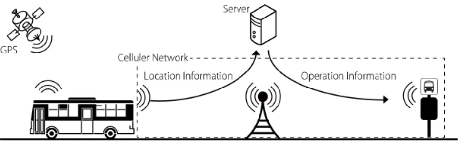
In the existing system that is the most popular in bus location systems, a communication device to connect to a cellular network is installed in buses and bus stops as shown in Figure 1.
Each bus sends own location information obtained from GPS to a management server through
the cellular network. The server stores and analyzes the received bus location information and
sends bus operation information including delay information to bus stops. The communication
costs in this system model are generally very expensive because many communication
devices are needed depending on the number of buses and bus stops. Therefore, it is
financially difficult to keep operating the system due to a high communication costs even if a
local government can introduce the system with the promised compensation from the central
government ministries.
Figure 1. Overview of a popular bus location system using a cellular network
As with our proposed method in Section 3, Zhian et al. has proposed the bus operation system that manages bus operation management without a cellular network [1]. This system grasps departure and arrival of buses using ZigBee [2] that is used to create wireless sensor networks.
In this system, ZigBee nodes are installed in buses and bus stops, and WSNs are created between a bus and a bus stop. This system regards as the arrival of the bus when the ZigBee node installed in the bus joins WSN created by the bus stop node, and the departure of the bus when the bus node leaves the WSN. These arrival and departure information are displayed on the bus stop indicator. In this system, WSNs are created independently from each other, and are not available to send the arrival/departure and location information of buses to a server located in an operation control center. Therefore, this system must use a cellular network (GSM/GPRS) to send these information to the server, and consequently it cannot reduce communication costs.
Iqbal et al. has proposed an operation management system for demand buses to operate efficiently buses upon request of passengers [3]. As same with the above system, ZigBee nodes are installed in buses and bus stops. A bus receives route information planned at an operation control center from a neighbor bus stop by using ZigBee. In this system, however, communications between the center and each bus stop are achieved by using a cellular network. Therefore, it is also difficult for this system to reduce communication costs significantly.
As mentioned above, several existing systems that apply the wireless sensor network technology have been proposed, but not the best way to use WSNs.
3. OUR PROPOSED SYSTEM 3.1 Overview
To solve the above problem, we propose a novel bus location system that is capable of
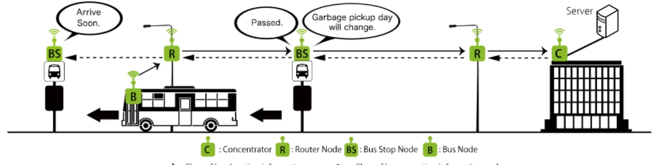
keeping operation without communication costs. Figure 2 shows an overview of our proposed
system. Our proposed system introduces multiple IEEE802.15.4-compliant sensor nodes in
order to construct WSNs in a bus service area. Sensor nodes are installed in buses, bus stops,
a management server and street lights along bus routes. These sensor nodes are called “Bus
node”, “Bus stop node”, “Concentrator” and “Router node”, respectively. Bus nodes send own
Figure 2. Overview of our proposed system
the management server in the operation control center, and collects some information from WSN. The management server stores all bus location information, generates bus operation information, and sends some information to bus stops through the concentrator. Bus stop nodes display not only the received bus operation information from the concentrator but also community event guides and announcements from the local government. Router nodes installed at utility poles and/or street lighting poles relay packets containing the above information. It is possible to construct wireless sensor networks independently from cellular networks of telecommunication carriers. Therefore, our proposed system requires no communication costs and can achieve bidirectional communication among all sensor nodes.
3.2 Wireless Communication Standard and Communication Protocol
In our proposed system, we adopt the IEEE 802.15.4 [4] as a wireless communication standard. The IEEE 802.15.4 standard is a basis for several communication protocols such as ZigBee, WirelessHART [5] and so on, and is also characterized by very low cost and low power consumption but lower transfer rate. Therefore, sensor nodes do not need a commercial power supply, and can be powered entirely by batteries or a solar power. In consequence, the size of WSN can be easily adjusted by installing and/or removing sensor nodes according to an increase or decrease in bus routes. Also, there are no serious problems caused by low transfer rate because most data traveling over the WSN is a text data such as location information and operation information.
There are communication protocols to construct WSNs such as ZigBee, JenNet [6] and
6LoWPAN [7]. We adopt DECENTRA II developed by Skyley Networks [8]. DECENTRA II
is a wireless communication protocol stack for wireless sensor devices. Sensor nodes installed
with DECENTRA II can immediately make multi-hop communications among them even if
the network topology changed by movement of buses, because DECENTRA II does not
require processes when a sensor node joins or leaves the network.
IEEE 802.15.4 MAC Header
(9 bytes)
DECENTRA II Header (31 bytes)
Payload (MAX: 85 bytes)
IEEE 802.15.4 MAC Footer
(2 bytes)
Information Type (1 byte)
Content Type (1 byte)
Data (MAX: 83 bytes) MAX: 127 bytes
Figure 3. Frame Format
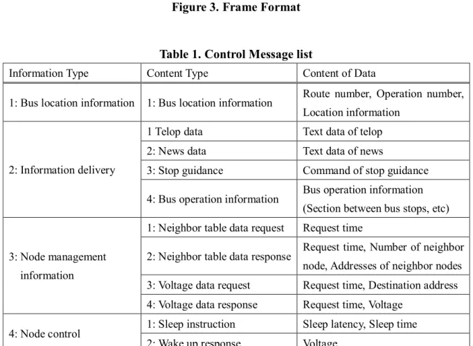
Table 1. Control Message list
Information Type Content Type Content of Data
1: Bus location information 1: Bus location information Route number, Operation number, Location information
2: Information delivery
1 Telop data Text data of telop
2: News data Text data of news
3: Stop guidance Command of stop guidance 4: Bus operation information Bus operation information
(Section between bus stops, etc)
3: Node management information
1: Neighbor table data request Request time
2: Neighbor table data response Request time, Number of neighbor node, Addresses of neighbor nodes 3: Voltage data request Request time, Destination address 4: Voltage data response Request time, Voltage
4: Node control 1: Sleep instruction Sleep latency, Sleep time 2: Wake up response Voltage
3.3 Information and Control Messages
Figure 3 shows the frame format of the system. We defined “Information Type” and “Content Type” fields in the payload of DECENTRA II/IEEE 802.15.4 frame in order to identify the type of information and control messages and add new messages in the future.
Table 1 shows the information and control message list. For example, the values of
Information Type and Content Type are both “1”, it is Bus location information that contains a
route number, an operation number and location information of a bus, and is sent from the bus
node to the concentrator. The route number is the number of the bus route. The operation
number is the number of service operated. These numbers are determined by the setting of the
bus-mounted device. The location information includes some data obtained by GPS (Time,
Latitude, Longitude, Fix quality and Number of satellites).
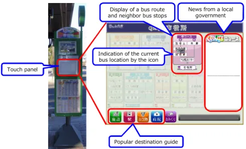
Popular destination guide
News from a local government Display of a bus route
and neighbor bus stops
Indication of the current bus location by the icon Touch panel
Figure 4. Bus stop with a touch panel display 4. IMPLEMENTATION
4.1 Sensor Node
We adopt “TWE-001 STRONG” produced by Tokyo Cosmos Electric Co., Ltd. [9] as a sensor node. This node is a wireless communication module that uses the 2.4 GHz band. This module runs on low current consumption (28 mA at transmission, 23.5 mA at reception, 1.3 µA at deep sleep). In addition, the module is capable of long-distance communication (Line-of sight distance is 3 km) when used with our adopted antenna that has 2 dBi gain and is omnidirectional. Under a noisy environment like an urban zone where there are a lot of Wi-Fi routers, the module can communicate with each other about 200 m.
4.2 Concentrator/Management Server
The management server connects to the concentrator via a serial cable and saves the data of the information or control message received from the concentrator, such as the bus location information and the voltage of router nodes, as log data. In addition, the management server generates the bus operation information based on the relationship between the current bus location and bus time tables, and sends the operation information to bus stops. In addition to this, the management server sends some messages to bus stop nodes and router nodes in order to control these nodes, and stores various information received from bus nodes, bus stop nodes and router nodes in the database.
4.3 Bus Stop Node/Bus Stop
Figure 4 shows our developed bus stop. The bus stop consists of an embedded PC, a sensor
node and a touch panel display. Some information received from the management server such
as the bus operation information and local government information are displayed on the
screen installed in front of the bus stop. Bus users can check the current bus location by the
blinking bus icon and the sound (music and audio guidance) at the bus stop.
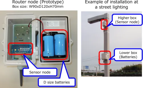
Sensor node
D size batteries
Router node (Prototype)
Box size: W90xD120xH70mm
Example of installation at a street lighting
Higher box (Sensor node)
Lower box (Batteries)
Figure 5. Router node and its installation example 4.4 Router Node
Figure 5 shows the router node. The router node is made of the sensor node, two D size batteries and the waterproof and dustproof box, and is just driven by these batteries. When the router node receives the bus location information message transmitted from the bus node, the router node finds the route to the concentrator, and forwards the message to the neighbor router node or the concentrator. In addition, all router nodes periodically notifies the concentrator of the own battery voltage, and go to sleep in order to reduce battery usage.
As shown in Figure 4, router nodes are installed separately divided into higher and lower parts in the actual field. The higher box contains the sensor node to improve the reachability of the radio wave away from surrounding trees and vehicles. The lower box contains batteries, the power switch and a serial port (also known as UART). Consequently, it is easier to do maintenance such as the replacement of batteries and rewriting the program of the sensor node.
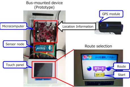
4.5 Bus Node/Bus-Mounted Device
Figure 6 shows the bus-mounted device. The bus-mounted device consists of a Linux microcomputer, a GPS module, the sensor node and a small touch panel display. Each equipment are attached to the serial port of the Linux microcomputer.
The bus-mounted device boots at the time of supplying power through the bus, and displays a
route selection screen on the touch panel. After a bus driver selects the route, the
microcomputer starts continuous measurement own position by GPS, and generates the bus
location information massage by combining the selected route number. The message is
transmitted to the concentrator through the sensor node periodically.
Touch panel Sensor node Microcomputer
Bus-mounted device (Prototype)
Route selection GPS module
Location Information
Route Start
Figure 6. Bus-mounted device
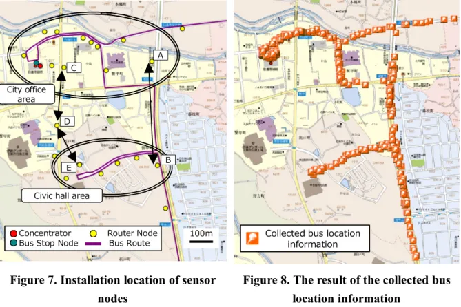
5. VERIFICATION EXPERIMENS AND THE RESULT
We have developed the prototype system and installed each equipment at a part of the community bus “Kururin Bus” in Nissin City, Aichi Prefecture, Japan in order to verify our proposed system. We have constructed a wide-area wireless sensor network in some bus service area of Kururin Bus. Distance of the target route for verification experiments is about 2 km. Figure 7 shows the installation location of each node. In This verification experiments, we have placed router nodes on the road sign poles and street lighting that are managed by Nissin City. Installation positions are decided in such a way that frame arrival rates between two points shall be 90% or more. The connectivity between the city office area and the civic hall area is realized by redundant two paths, namely between router A and route B, and between router C, router D and router E. Also, we have installed the management server in the city office, the bus stop in front of the city office, and the bus-mounted device in the currently operated bus. The bus-mounted device sends own location information message to the concentrator every 5 seconds. The management server saves these location information messages as reception log.
Figure 8 shows the result of the collected bus location. The management server has almost
collected the location of the traveling bus although several frames are lost and overtaken. In
our system, the management server can grasp the location of the bus if at least one bus
location information message is received by the concentrator. If one frame loss or frame
overtaking occurs, the error in position of the bus is about 55 m because the bus travels at
about 40 km/h and the bus node sends the bus location information message for 5 seconds
interval. Therefore, the management server can correctly estimate the bus traveling section
between bus stops even if several frame losses and frame overtaking occur, and our proposed
system can provide the operation information at the bus stop. As a result of verification
Concentrator Router Node 100m Bus Stop Node Bus Route City office
area
Civic hall area
A
B C
E D
Collected bus location information