Synchronization Pattern of Chaotic System Containing Time Delay
Seiya Kita, Takuya Nishimoto, Yoko Uwate and Yoshifumi Nishio Dept. of Electrical and Electronic Engineering, Tokushima University,
2-1 Minamijosanjima, Tokushima, 770-8506 Japan Email: { kita, nishimoto, uwate, nishio } @ee.tokushima-u.ac.jp
Abstract—In this study, we investigate synchronization phe- nomena observed in coupled chaotic circuits containing time delay. Various synchronization states can be observed . Espe- cially, we focus on relationships between synchronization state and parameters. Coexisting synchronization states depending on initial values can be observed in the proposed system by carrying out computer calculation. Moreover, we investigate the effect of chaotic behaviour on subcircuit to synchronization states. Chaotic strength of subcircuit possibly induces anti-phase synchronization.
I. I
NTRODUCTIONRecently, researches on chaos phenomena have been at- tracting attention. The chaos phenomenon shows a complex unpredictable behavior. It can be observed in various science fields, such as biology, economics, physics and astronomy.
A number of studies on synchronization of coupled chaotic circuits have been made [1]. The synchronization is one of the typical phenomena observed in nature. There are flashing of fireflies, rhythm of the heart cells and laser oscillation in examples of the synchronization. In addition, synchronization phenomenon, there is an advantage that a large energy is obtained by synchronizing the small energy. By utilizing this property, it is possible to realize a pacemaker that can control the synchronization of the cardiomyocytes of the heart, which is actually used as a medical device. On the other hand, electric circuit observed the chaotic phenomena. There are a lot of merits using electric circuit to investigate chaotic behaviour. For instance, inexpensive element, short experiment time, high repeatability of the experiment and so on. There are various types of chaotic circuits. We focus on the chaos circuit including a also time delay in that [2]-[4].
In this study, we investigate two coupled chaotic circuits containing time delay. Especially we focus on the synchro- nization phenomena of our proposed circuit. By carrying out computer simulations, two types of synchronization phenom- ena depending on initial values can be observed. Moreover, we investigate the relationships between parameters and syn- chronization phenomena.
II. C
IRCUITM
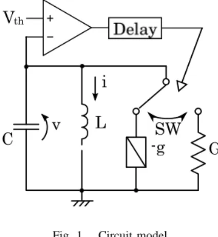
ODELThe chaotic circuit used in this study is shown in Fig. 1. The circuit is composed of a − gLC oscillator and the amplitude control loop. − g is a negative resistance, the current flowing
through the inductor L is i, the voltage between the capacitor C is v. Switching operation is shown in Fig. 2, it controls the amplitude of the oscillator. The switching controls the amplitude of v by changing from the negative resistance to the positive resistance when the amplitude is larger than the threshold value. This switching operation is included time delay. T
ddenotes the time delay. First, the switch is connected to a negative resistance. v is amplified while oscillating, the amplitude is bigger a certain threshold voltage V
th. The switch does not immediately connect in the positive resistance however the switch is connected after T
dseconds. In the computer simulation, T
dis set to π/(1 − α
2).
C v L
i V
SW -g G
th
Fig. 1. Circuit model.
The circuit equations of the system are given as follow:
(A) In case of switch connected to -g,
L di
dt = v C dv
dt = gv − i.
(1)
(B) In case of switch connected to G,
L di
dt = v C dv
dt = − Gv − i.
(2)
By changing the parameters and variable as follows:
i =
√ C
L V
thx, v = V
thy, t = √ LCτ ,
- 52 -
IEEE Workshop on Nonlinear Circuit Networks December 12-13, 2014
the switch is connected to negative resistor DELAY
Vth
time (a)
(b)
OPERATION v
(a) v<
(b) v>
Vth
time
time Vth
DELAY
Fig. 2. Switching operation.
g
√ C
L = 2α and G
√ C L = 2β .
The normalized circuit equations of the system are given as follow:
(A) In case of switch connected to − g, { x ˙ = y
˙
y = 2αy − x. (3)
(B) In case of switch connected to G, { x ˙ = y
˙
y = − 2βy − x. (4)
III. T
WO COUPLED CHAOTIC CIRCUITSFigure 3 shows the schematic of two chaotic circuits con- taining time delay coupled by a inductor. By changing the parameters and variables as follows:
i
n=
√ C
L V
thx
n, v
n= V
thy
n, t = √ LCτ , g
√ C
L = 2α, G
√ C
L = 2β and γ = L L
0;
The normalized circuit equations of the system are given as follows:
(A) In case of the switch is connected to − g, { x ˙
n= y
n˙
y
n= 2αy
n− x
n− γ(x
n+1− x
n). (5) (B) In case of switch connected to G,
{ x ˙
n= y
n˙
y
n= − 2βy
n− x
n− γ(x
n+1− x
n). (6) where
(n = 1, 2), x
3= x
1.
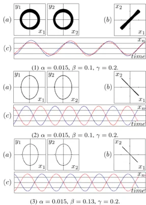
Figure 4 shows simulation results in case of two coupled chaotic circuits. Figure 4 (1) and (2) are two types of syn- chronization phenomena depending on the initial values which are corresponding to almost in-phase synchronization and
C v L
i V
SW
-g G
L
C v L
i V
SW -g G
0
th th
2 2
1 1
Fig. 3. A coupled 2 chaotic circuits containing time delay
anti-phase synchronization states, respectively. By increasing the parameter β , anti-phase synchronization phenomena are induced and in-phase synchronization gradually become unsta- ble. The parameter β qualitatively denotes the chaotic strength.
Namely, it is considered that anti-phase synchronization state is induced by chaotic behavior of each subcricuit as shown in Fig. 4 (3).
(1)α= 0.015,β= 0.1,γ= 0.2.
(2)α= 0.015,β= 0.1,γ= 0.2.
(3)α= 0.015,β= 0.13,γ= 0.2.
Fig. 4. Simulation results of N = 2. (a) Attractor. (b) Lissajous figure.
(c) Timewaveform. Red and blue colors denotex1andx2respectively.
- 53 -
IV. C
ONCLUSIONIn this study, we have investigated synchronization phenom- ena observed by coupled chaotic circuits containing time delay.
As a result, induction of anti-phase synchronization caused by chaotic strength of subcircuit have clarified. In our future work, we will investigate the parameter region of coexisting synchronization and the mechanism of induction of anti-phase synchronization phenomena.
R
EFERENCES[1] Louis M. Pecora and Thomas L. Carroll, “Synchronization in Chaotic Systems,” PHYSICAL REVIEW LETTERS, vol. 64, no.8, pp. 821-824, Feb. 1990.
[2] T. Maruyama, N. Inaba, Y. Nishio and S. Mori, “Chaos in an Auto Gain Controlled Oscillator Containing Time Delay,” Trans. IEICE, vol. J 72-A, pp. 1814-1820, Nov. 1989.
[3] T. Maruyama, N. Inaba, Y. Nishio and S. Mori, “Chaos in Self Oscillator Circuit Containing Time Delay,” Proceedings of IEEE Midwest Sympo- sium on Circuits and Systems (MWSCAS’90), vol. 2, pp. 1055-1058, Aug. 1990.
[4] T. Kousaka, Y. Umakoshi, T, Ueta and H. Kawakami, “Bifurcation of nonlinear circuits with periodically operating switch,” IEEE, vol. 84, Issue 1, pp. 7583, Jan. 2001.