SUMMARY Recently, wearable wireless devices or terminals have be- come hot a topic not only in research but also in business. Implantable wireless devices can temporarily be utilized to monitor a patient’s condition in an emergency situation or to identify people in highly secured places.
Unlike conventional wireless devices, wearable or implantable devices are used on or in the human body. In this sense, body-centric wireless com- munications (BCWCs) have become a very active area of research. Radio- frequency or microwave medical devices used for cancer treatment systems and surgical operation have completely different functions, but they are used on or in the human body. In terms of research techniques, such med- ical devices have a lot of similarities to BCWCs. The antennas to be used in the vicinity of the human body should be safe, small and robust. Also, their interaction with the human body should be well considered. This re- view paper describes some of the wearable antennas as well as implantable antennas that have been studied in our laboratory.
key words: wearable antenna, implantable antenna, body-centric wire- less communications, RFID, hyperthermia, medical device, human body, phantom
1. Introduction
Recently, wearable wireless devices or terminals have be- come a hot topic not only in research but also in business.
They can make our daily life more convenient and safer.
Also, they can improve quality of life (QOL) of elderly peo- ple or patients in hospitals.
Implantable wireless devices can be utilized temporar- ily to monitor a patient’s condition in an emergency situa- tion or to identify people in highly secured places. Today, they are sometimes used permanently for specific biological monitoring systems.
Unlike conventional wireless devices, wearable or im- plantable devices are used on or in the human body. In this sense, body-centric wireless communications (BCWCs) have become a very active area of research. There are numerous applications, such as personal health care sys- tems, smart homes, personal entertainment, identification systems, and so on[1],[2].
On the other hand, radio-frequency or microwave med- ical devices used for cancer treatment systems and surgical operation have completely different functions, and are used on or in the human body[3]–[5]. In terms of research tech- niques, such medical devices have a lot of similarities to BCWCs. In general, the problem of a small antenna used in
Manuscript received April 16, 2015.
Manuscript revised August 17, 2015.
†The authors are with the the Center for Frontier Medical En- gineering, Chiba University, Chiba-shi, 263-8522 Japan.
a) E-mail: [email protected]
DOI: 10.1587/transcom.2015ISI0002
the vicinity of the human body can be treated as “boundary value problem” in which the human body is considered as a lossy medium. By applying Sommerfeld integral, electro- magnetic fields around the antenna could be found in prin- ciple. However, in reality and simplicity, an individual case is treated appropriately in a specific manner.
The antennas to be used in the vicinity of the human body should be safe, small and robust. Also, their interac- tion with the human body should be well considered. For experimental evaluation of such interaction, human-body phantoms should be used instead of a real human body [1],[6].
This review paper describes some of the wearable an- tennas as well as implantable antennas that have been stud- ied in our laboratory. Section 2 introduces two typical ex- amples of wearable antennas: a wearable dual-mode an- tenna that can transmit various biological information with less power, and a radio frequency identification (RFID) an- tenna that detects urination for adults. Section 3 intro- duces three different types of implantable antennas: an im- plantable RFID tag antenna to monitor biological informa- tion, two microwave antennas for thermal therapy (hyper- thermia) as well as surgical operation, and a small antenna for a capsule endoscope.
2. Wearable Antennas
This section introduces two typical examples of wearable antennas. The first one is a wearable dual-mode antenna that can transmit various biological information with less power.
The second one is an RFID antenna that detects urination for adults.
2.1 Wearable Dual-Mode Antenna
Recently, BCWCs have become a very active area of re- search because of their numerous applications, such as per- sonal healthcare systems, smart homes, personal entertain- ment, identification systems, and so on[1],[2].
The frequency used for most practical applications of BCWCs ranges from a few MHz to 2.45 GHz. In our previ- ous study[7], a conventional top-loaded monopole antenna shown in Fig. 1 is employed. The antenna has low-profile dimension (4-mm thick) and has no matching structure for simplicity.
Figure 2(a) shows a numerical human-body model.
The antenna is placed at the navel as a transmitter. Fig- Copyright c2016 The Institute of Electronics, Information and Communication Engineers
Fig. 1 Structure of the antenna[7].
Fig. 2 Human-body model and electric field distributions[7]. A trans- mitter is placed at the navel and its output power is the same.
Fig. 3 Estimated input power when 1-V excitation is assumed[7].
ures 2(b) and (c) illustrate calculated electric field distribu- tions around the human-body model at 3 MHz and 3 GHz [7]. The radiation efficiency at 3 MHz is almost zero be- cause the field around the human body mainly consists of the electrical stored energy. On the contrary, at 3 GHz, the radiation efficiency reaches 48% and strong radiation from the antenna is observed.
Figure 3 shows input power versus frequency for the antenna with 1-V excitation[7]. The use of lower frequency would be more efficient in terms of power consumption.
Figure 4 illustrates an example of a personal health- care system. Various bio-signals from different bio-sensors are sent to a repeater through on-body communications at 21 MHz, and these bio-signals are transmitted to an external device (access point) in off-body mode at 2.45 GHz. There- fore, significantly low power consumption can be realized [7]for on-body communications.
Figure 5 shows the structure of a practical dual-mode
Fig. 4 An example of a personal healthcare system.
Fig. 5 Structure of a dual-mode antenna[8].
Fig. 6 Simulated radiation patterns at 2.45 GHz[8].
antenna[8]. It acts as a receiver in on-body mode (21 MHz) and a transmitter in off-body mode (2.45 GHz). Regarding the polarization generated from an antenna, vertical polar- ization to the human-body surface is suitable for on-body mode and horizontal polarization for off-body mode. The antenna in Fig. 5 is designed to generate such proper polar- izations.
Figure 6 shows the simulated radiation patterns with the high-resolution human-body model. From the results, the radiation patterns in both planes are relatively omni- directional with no deep nulls in the half-sphere.
We are planning to take measurements on the antenna with a human torso phantom fabricated in our laboratory, shown in Fig. 7.
Fig. 7 Torso phantom for measurement.
Fig. 8 Suggested simple urination detection system.
2.2 Urination Detection System Using RFID
Some admitted patients wear diapers. In many hospitals across Japan, the diapers of care-receivers are changed sev- eral times a day. The care personnel can only know whether the care-receivers urinated or not by removing their clothes.
Thus, in this section, a simple urination detection system using RFID[9]–[11]is presented in order to provide a com- fortable healthcare environment for the patients and improve the quality of medical support.
Figure 8 shows our proposed simple system. In our proposed urination detection system, a tag is embedded into each diaper worn by a care receiver and the care-personnel brings a reader close to the tag. If the paper diaper is dry, the RFID tag embedded into it can communicate with the reader. On the contrary, if it is wet enough, the urination prevents communication from the tag. Therefore, urination is detected by whether the tag can communicate with the reader or not. This system allows the care personnel to know whether or not a patient has urinated because the urination changes the characteristics of the antenna and makes it un- able to communicate to the reader. Thus, the physical and mental strain of both patients and their care personnel can be reduced.
In this section, an antenna that can match the impedance of the integrated circuit (IC) chip for RFID is designed and analyzed. The operating frequency of the an- tenna is 950 MHz, which is the permitted RFID in Japan.
The structure of the proposed RFID antenna is shown
Fig. 9 Antenna structure.
Table 1 Electrical constants of calculation model.
in Fig. 9. The proposed antenna is embedded into the paper diaper. The thickness of the paper diaper is 6 mm and the depth of the antenna in the diaper is 3 mm. The RFID an- tenna in each paper diaper must be compact and flat. Due to the size limitation for the RFID tags, the proposed antenna has a meandering structure. For impedance matching, a loop structure is used in our antenna design[12]. Moreover, the capacitance of the antenna can be adjusted by the parallel structure near the IC chip. The impedance of the antenna matches that of the IC chip in each dry paper diaper worn on a human body.
In the calculation, the wet diaper is defined by chang- ing the electrical properties of the diapers. The electrical properties of these models are shown in Table 1. In our re- search, a two-thirds muscle-equivalent phantom was used for the human model[13].
Figure 10 illustrates a fabricated phantom. This phan- tom can simulate urination by a tube embedded. Figure 11 shows the manufactured antenna in a paper diaper. For mea- surement, the urination is defined as an aqueous solution.
The aqueous solution has the same electrical properties as urine. The electric properties of urination is derived from [14]. The calculated and measured reflection coefficients of the antenna are shown in Fig. 12. The results are the char- acteristics of the antenna embedded into a paper diaper on the phantom. The reflection coefficients are converted by the impedance of the IC chip [15]. From the results, the antenna has a good impedance matching at 950 MHz when the paper diaper is dry. On the other hand, the antenna does not resonate when the paper diaper is wet enough. Both the calculated and measured results are in good agreement.
Based on those results in the wet diaper, the impedance can- not matched between the antenna and the IC chip, therefore the power is not supplied to the IC chip from the antenna.
The experiments were carried out by using a handy reader (DOTR-920J, Tohoku Systems Support Co., Ltd.).
The output power of the handy reader is 250 mW. Five peo- ple each wore a diaper and lay down on a bed. Then we
Fig. 10 Phantom between abdomen and femoral.
Fig. 11 Manufactured antenna on a paper diaper.
Fig. 12 Reflection coefficient of proposed tag antenna.
held a reader close to the tag and checked whether the tag could communicate with the reader or not. For the study of the wet diaper, the diaper was moistened by 120 milliliters of water solution. From the experimental verification, urina- tion could be detected by the proposed system. In addition, the effect of comforter was very little. This system is very simple and low cost, so it is easy to implement.
3. Implantable Antennas
This section introduces three different types of implantable antennas, namely, an implantable RFID tag antenna to mon- itor biological information, two microwave antennas for thermal therapy (hyperthermia) as well as surgical opera- tion, and a small antenna for a capsule endoscope.
3.1 Implantable RFID Tag Antenna
RFID systems have also been introduced for the manage- ment of medical instruments to improve the quality of med- ical services. In recent years, the combination of such a
Fig. 13 Antenna geometry and three-layered phantom.
system with a biological monitoring system through perma- nent implantation in the human body has been suggested to reduce malpractice events and lessen patient suffering [16],[17]. The complex human body causes an extreme re- duction of the antenna’s performance; therefore, some of the essentials of antenna design should be completely reconsid- ered: (a) the physical antenna size should be miniaturized such that the antenna can be injected into the human body via a syringe in order to reduce pain during injection, and (b) the antenna should be coated with a biocompatible material to avoid direct contact with the human tissues and reduce attenuation from the human body.
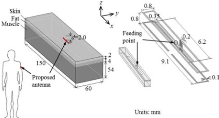
This section presents an implantable RFID tag antenna design that can match the conjugate impedance of most IC chips at 2.45 GHz [18]. The proposed antenna can be in- jected into the human body through a biological syringe, owing to its compact size. The proposed antenna has a folded structure[19]. The performance of the proposed an- tenna is investigated by simulating its impedance character- istic, transmission coefficient, and received power using a finite element method. Furthermore, a three-layered phan- tom is introduced into the simulation and measurement as a substitute for a real human arm[20].
The geometry of the proposed antenna is shown in Fig. 13. The antenna is fabricated by bending a narrow strip of 0.1 mm into a folded structure to reduce the phys- ical size. The total size of the proposed antenna is 9.1 mm
×0.8 mm×0.8 mm. Moreover, the loop structure is placed near the feeding point to match the aforementioned conju- gate impedance of the IC chip. Finally, the proposed an- tenna is 9.3 mm×1.0 mm×1.0 mm after coating with glass (εr = 5.0). We evaluated the antenna performance by a three-layered human phantom as a substitute for the hu- man arm. The human phantom was constructed with skin (εr = 38.0, σ = 1.5 S/m), fat (εr = 5.3σ =0.1 S/m), and muscle (εr=52.7,σ=1.7 S/m) at the desired frequency of 2.45 GHz [21] with thicknesses of 2 mm, 4 mm, and 54 mm, respectively. The size of the phantom was 150 mm×60 mm
×60 mm. In addition, we have embedded the proposed an- tenna in the fat layer at a depth of 2 mm because the loss in fat is less than that in skin and muscle.
In this section, we discuss the impedance character-
Fig. 14 Impedance characteristics of the proposed antenna.
Fig. 15 Measurement of the impedance characteristics.
istics when the dipole antenna is bent into a folded struc- ture. The loop structure near the feeding point can appar- ently improve the input impedance of the proposed antenna 9.5+ j54.1Ω, which approaches the conjugate impedance of 9.3 − j55.2Ω. Figure 14 shows a comparison of the simulated and measured input impedances. As a result, the measured impedance of 9.1+ j47.4Ω shows good agree- ment with the simulation. Figures 15(a) and (b) show the fabricated antenna, which is connected by a one quarter- wavelength balun (with a length of 30.6 mm at 2.45 GHz) and a three-layered human phantom, respectively. In our experiment, a hole is dug into the phantom to connect the balun to the antenna and fix the antenna in the fat layer of the three-layered phantom.
Estimation of the path loss between an external reader/writer (R/W) and a tag is essential because the tag is embedded in the human body, which is a complex environ- ment. Therefore, the transmission coefficient and received power are analyzed and discussed.
The proposed antenna is in the fat layer of the three- layered phantom, and the circular polarized (CP) antenna is set above the phantom at a specific height (h). A patch antenna with perturbation elements is used as a CP antenna [22]. The maximum CP antenna gain and bandwidth (<3- dB axial ratio) are 2.9 dBi and 28 MHz, respectively.
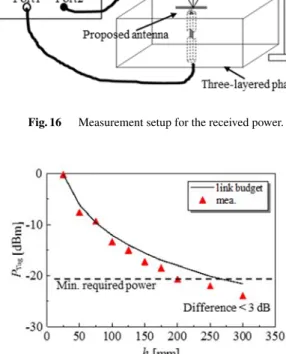
In the RFID system, the link budget generally is used for estimating the amount of power that is actually received by a tag placed at a distancer from the isotropic antenna, which is denoted as the power required for R/W. A minimum RF input power of 10μW to 50μW (−20 dBm to−13 dBm) is required to power up the chip[23].
Fig. 16 Measurement setup for the received power.
Fig. 17 Received power comparison between the link budget and the measurement result when the CP antenna is placed above the three-layered phantom ath=25−300 mm.
Figure 16 shows the measurement setup for the re- ceived power. Port 1 and Port 2 of the network analyzer connect to the proposed antenna and CP antenna, respec- tively; a fixed antenna support is used to change the height of the CP antenna. The measured gains of the proposed an- tenna and CP antenna are−19.3 and 2.2 dBi, respectively.
Figure 17 shows the comparison of the calculated re- ceived power by using the link budget and the measured received power when the CP antenna is located at h = 25−300 mm. The received power is obtained by using a transmission coefficientS21 and the input power to the CP antenna of 30 dBm (1 W). As a result, it is found that when the CP antenna is placed ath=25−195 mm, the measured received power can satisfy the minimum required power of
−20 dBm. Moreover, the measured results agree with the calculations because the difference is less than 3 dB.
3.2 Therapeutic Techniques of Microwave Energy (a) Microwave hyperthermia
In recent years, various types of medical applications of microwave antennas have been widely investigated. Typ- ical recent applications include medical information trans- mission, diagnosis, and treatment. This section introduces, microwave techniques for treatments, that employ the ther- mal effect of the electromagnetic wave, such as a thermal treatment of cancer called hyperthermia and surgical devices
ties for cancer treatment, utilizing the difference of thermal sensitivity between tumor and normal tissue and is one of the most effective medical applications of microwave tech- niques. In this treatment, the tumor is heated up to the ther- apeutic temperature between 42 and 45◦C without overheat- ing the surrounding normal tissues [24]. In addition, the effect of other cancer treatments such as radiotherapy and chemotherapy can be enhanced by using them together with hyperthermia.
There are several energy sources for heating tumors such as hot water, ultrasound, electromagnetic wave, etc.
Microwave energy is one of the heating sources used for localized hyperthermia[25]. The frequency for microwave hyperthermia ranges from several hundred to several thou- sand MHz (i.e., up to several GHz). For hyperthermia treatments, heating devices using 430 MHz, 915 MHz, and 2.45 GHz have been commercially developed.
In addition, several different types of microwave heat- ing schemes have been reported. Among them, interstitial microwave heating can be applied for localized tumors[26].
With this technique, an array of thin microwave antennas is inserted into the tumor and radiate microwave energy di- rectly into the target[25],[27], permitting effective and re- liable heating of the tumor.
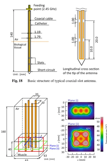
The authors have developed coaxial-slot antennas[28], which are used for interstitial microwave heating, and have many experiences of actual clinical treatments in collabora- tion with medical doctors. Figure 18 shows the basic struc- ture of a typical coaxial-slot antenna. Before a clinical treat- ment, many types of heating patterns around the antenna were calculated to deal with various shapes of tumors. For example, Fig. 19 shows a calculated temperature distribu- tion around the array applicator composed of four coaxial- slot antennas under some practical assumptions, with an op- erating frequency of the antenna at 2.45 GHz, which is one of the industrial, scientific and medical (ISM) frequencies.
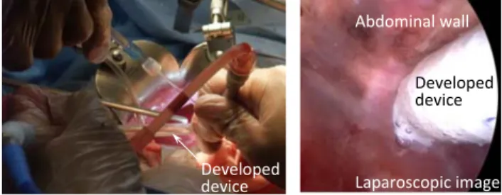
Figure 20 shows one of the photographs during the treatment taken by our developed antennas. Detailed infor- mation of the treatment is described in[29].
(b) Microwave surgical device
Generally, electrical scalpels have been used for sur- gical operation. Conventional electrical scalpels utilize an RF current (from several hundred kHz to several MHz) and can realize both tissue coagulation and dissection. However, these devices have some problems. First, the device requires an external electrode, which sometimes causes burn injury around it. Moreover, the RF current may go through an un- expected part of the human body and cause involuntary mus- cle movement. In addition, since the device generates an ex- cessively high temperature, biological tissue is carbonized, and fog will be generated. This is one of the most serious
Fig. 18 Basic structure of typical coaxial-slot antenna.
Fig. 19 Calculated temperature distributions around the array applica- tor composed of four coaxial-slot antennas. (Total radiation power: 20 W, Blood flow rate: 8.33×10⁻⁶ m3/kg·s[30], Initial temperature: 37.0◦C, Heating time: 300 s.)
Fig. 20 Actual clinical treatment by our developed antenna.
problems, especially in laparoscopic surgery.
Massive bleeding during a surgical operation could be dangerous for a patient. Laparoscopic surgery cannot be continued under such massive bleeding, because the view of the laparoscope is reduced. Therefore, hemostasis is one of the most important treatments. The authors have been
Fig. 21 Basic structure of stick-type hemostasis device.
Fig. 22 Animal experiment.
studying tissue coagulation devices for hemostasis by using microwave energy.
The authors have developed several microwave surgi- cal devices, such as forceps-type, scissor-type, knife-type and stick-type devices. A stick-type device based on heli- cal structure for tissue coagulation and hemostasis is intro- duced. Figure 21 shows the basic configuration of the device tip. Whole helical part shows covered with polytetrafluo- roethylene (PTFE) material for prevention of tissue adhe- sion. The operating frequency of the antenna is 2.45 GHz.
With the help of medical doctors, the authors have done several animal experiments using swine. The effectiveness of the device could be confirmed in the living tissue with blood flow. Figure 22 is one of the photographs taken during the animal experiment using our developed device.
3.3 Antenna for Capsular Endoscope
Wireless power transmission (WPT) has been investigated for many applications, for example, the Space Solar Power Satellite/station (SPS) plan [31]and wireless charging for electronic products. It is an attractive charging system can- didate for capsular endoscopes. Capsular endoscopes are noninvasive diagnosing devices for digestive organs. They can diagnose the small intestine, which conventional endo- scopes cannot reach, and are less uncomfortable to patients.
However, current capsular endoscopes can take only a lim- ited number of photographs because of their small battery capacity. The authors have been developing a capsular en- doscope with a WPT system that uses microwaves for con- stant charging; no batteries are needed. In this capsular
Fig. 23 Antenna for capsular endoscope.
endoscope with the WPT system, because the battery can be eliminated and the WPT and RF transmission antennas can be merged, a significant space saving is possible. Ac- cording to[32], 315–600 MHz band is a suitable operating frequency due to its transmission characteristics and safety for the human body. Therefore, in our study, 433.92 MHz, which is one of the ISM frequencies, is employed for the op- eration. Previously, a small receiving antenna in the capsular endoscope for the WPT was proposed in[33]. However, the bandwidth of the receiving antenna was not enough because of shifting of the resonance frequency. Therefore, in this study, an antenna, that can improve the bandwidth and the transmitting efficiency, is proposed.
Figure 23(a) shows the structure of the proposed re- ceiving antenna, which is designed to coil around the dielec- tric case, in order to effectively receive power radiated from the transmitting antenna. Here, a helical antenna with a di- ameter of 9 mm and a height of 16 mm is proposed based on the size of commercially available products. In addition, the input impedance of a normal helical antenna is too low to match 50Ω, so two conductor sheets are set near the feed- ing point to improve impedance matching. The width and length of the sheet are 3.4 mm and 8.6 mm, respectively.
Figure 23(b) shows the proposed receiving antenna inside a capsular case. The length and diameter of the case are 24 and 11 mm, respectively.
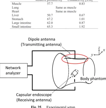
Some results of the performance evaluations by the nu- merical calculations are described in[34]. In order to eval- uate some performances of the antenna, a realistic abdomen phantom has been developed (Fig. 24). This phantom con- sists of muscle, lung, heart, liver, stomach, large intestine, and small intestine. The electrical properties of each part are listed in Table 2. Figure 25 shows a setup of experi- mental evaluation for antenna performances using the de- veloped phantom. The receiving antenna shown in Fig. 23 is placed in the small intestine and a half-wavelength dipole antenna is employed as a transmitting antenna. Figure 26 shows the results of the measurement. In calculations and measurements of the transmission coefficient, two directions of transmitting dipole antenna are considered. From the re- sults, good agreements between calculation and measure- ment are observed. Moreover, minimum value of the re-
Fig. 24 Abdomen phantom.
Table 2 Electrical properties of phantom (target value).
Fig. 25 Experimental setup.
flection coefficient and maximum value of the transmission coefficient are observed around the operating frequency.
4. Conclusion
This paper has reviewed some of the wearable antennas and implantable antennas that have been studied in our labora- tory. Section 2 introduced a small wearable dual-mode an- tenna that can transmit various biological information with less power, and an RFID antenna that detects urination by adults. Section 3 introduced an implantable RFID tag an- tenna to monitor biological information, two microwave thin antennas for thermal therapy (hyperthermia) as well as sur- gical operation, and a small antenna for a capsule endo- scope.
Fig. 26 Calculated and measured results.
Different types of human-body phantoms have also been introduced for experimental evaluation of antenna per- formance.
The authors hope this review paper will serve as a ref- erence for relevant research fields and will stimulate partic- ularly younger researchers and students to study these topics further.
Acknowledgments
The authors would like to acknowledge all the past and present students in our laboratory who have contributed a lot to these studies further.
References
[1] P.S. Hall and Y. Hao, Antennas and propagation for body-centric wireless communications, Artech House, Norwood, MA, 2012.
[2] M. H¨am¨al¨ainen, A. Taparugssanagorn, J. Iinatti, and R. Kohno, “Ex- ploitation of wireless technology in remote care processes,” IEICE Trans. Commun., vol.E92-B, no.2, pp.373–378, Feb. 2009.
[3] A. Rosen, M.A. Stuchly, and A.V. Vorst, “Applications of RF/microwaves in medicine,” IEEE Trans. Microw. Theory Techn., vol.50, no.3, pp.963–974, March 2002.
[4] F. Sterzer, “Microwave medical devices,” IEEE Microw. Mag., vol.3, no.1, pp.65–70, March 2002.
[5] C.P. Hancock, P. Burn, C.I. Duff, R. Sloan, M. White, J. Bishop, A.M. Goodman, M. Booton, M.S. Chaudhry, S. Morris, N.
Dharmasiri, B.P. Saunders, P. Sibbons, C. Gulliford, P. Wall, and
[7] N. Haga and K. Ito, “Frequency dependence of on-body channels with top-loaded monopole antennas in the range of HF to UHF,”
Proc. 2009 Asia Pacific Microwave Conference, pp.2208–2211, 2009.
[8] Y. Oya, K. Ito, and K. Saito, “Design of dual-mode antenna at 21 MHz and 2.45 GHz for medical applications,” Proc. 2014 In- ternational Symposium on Antennas and Propagation Conference, pp.587–588, 2014.
[9] H.-E. Nilsson, J. Siden, and M. Gulliksson, “An incontinence alarm solution utilizing RFID based sensor technology,” 2011 IEEE In- ternational Conference on RFID-Technologies and Applications, pp.359–363, 2011.
[10] H. Nakajima, M. Takahashi, K. Saito, and K. Ito, “Simple urina- tion detection system using RFID,” IEICE Communications Ex- press, vol.2, no.3, pp.98–103, 2013.
[11] H. Nakajima, M. Takahashi, K. Saito, and K. Ito, “Development of RFID antenna for detection of urination,” IEICE Trans. Commun., vol.E96-B, no.9, pp.2244–2250, Sept. 2013.
[12] N. Michishita and Y. Yamada, “A novel impedance matching struc- ture for a dielectric loaded 0.05 wavelength small meander line an- tenna,” 2006 IEEE Antennas and Propagation Society International Symposium, pp.1347–1350, 2006.
[13] S. Gabriel, R.W. Lau, and C. Gabriel, “The dielectric properties of biological tissues: II. Measurements in the frequency range 10 Hz to 20 GHz,” Phys. Med. Biol., vol.41, no.11, pp.2251–2269, April 1996.
[14] C. Gabriel, “Compilation of the dielectric properties of body tissues at RF microwave frequencies,” Brooks Air Force Technical Report AL/OE-TR-1996-0037, 1996.
[15] A. Yamada, S. Obayashi, H. Shoki, and H. Arai, “Evaluation for RFID tag antenna by antenna clearance based on power reflec- tion coefficient,” IEICE Technical Report, A·P2010-134, 2011 (in Japanese).
[16] A. Sani, M. Rajab, R. Foster, and Y. Hao, “Antennas and propa- gation of implanted RFIDs for pervasive healthcare applications,”
Proc. IEEE, vol.98, no.9, pp.1648–1655, 2010.
[17] P. Rotter, B. Daskala, and R. Compano, “RFID implants: Oppor- tunities and and challenges for identifying people,” IEEE Technol.
Soc. Mag., vol.27, no.2, pp.24–32, 2008.
[18] M. Usami and M. Ohki, “Theμ-chip: An ultra-small 2.45 GHz RFID chip for ubiquitous recognition applications,” IEICE Trans. Elec- tron., vol.E86-C, no.4, pp.521–528, April 2003.
[19] H. Lin, M. Takahashi, K. Saito, and K. Ito, “Design of small implantable RFID antenna for 2.4 GHz band for in-body wire- less communication,” IEICE Communications Express, vol.2, no.2, pp.31–35, Feb. 2013.
[20] H.-Y. Lin, M. Takahashi, K. Saito, and K. Ito, “Performance of im- plantable folded dipole antenna for in-body wireless communica- tion,” IEEE Trans. Antennas Propag., vol.61, no.3, pp.1363–1370, March 2013.
[21] Dielectric Properties of Body Tissues (IFAC), http://niremf.ifac.cnr.
it/tissprop/
[22] H. Lin, M. Takahashi, K. Saito, and K. Ito, “Design of miniature implantable tag antenna for radio-frequency identification system at 2.45 GHz and received power analysis,” IEICE Trans. Commun., vol.E97-B, no.1, pp.129–136, Jan. 2014.
[23] L. Harvey, RFID Design Principles, Second Ed., ch. 5, Feb. 2012.
[24] M.H. Seegenschmiedt, P. Fessenden, and C.C. Vernon, Eds., Thermoradiotherapy and Thermochemotherapy, Medical Radiology,
pp.840–845, Oct. 2014.
[27] J.C. Lin and Y.-J. Wang, “Interstitial microwave antennas for ther- mal therapy,” Int. J. Hyperther., vol.3, no.1, pp.37–47, 1987.
[28] K. Ito, K. Ueno, M. Hyodo, and H. Kasai, “Interstitial applicator composed of coaxial ring slots for microwave hyperthermia,” Proc.
Int. Symp. Antennas Propagation, pp.253–256, 1989.
[29] K. Saito, H. Yoshimura, K. Ito, Y. Aoyagi, and H. Horita, “Clini- cal trials of interstitial microwave hyperthermia by use of coaxial-s- lot antenna with two slots,” IEEE Trans. Microw. Theory Techn., vol.52, no.8, pp.1987–1991, 2004.
[30] P.M.V. Berg, A.T. De Hoop, A. Segal, and N. Praagman, “A com- putational model of the electromagnetic heating of biological tis- sue with application to hyperthermic cancer therapy,” IEEE Trans.
Biomed. Eng., vol.BME-30, no.12, pp.797–805, Dec. 1983.
[31] C.T. Rodenbeck, M.-Y. Li, and K. Chang, “A phased-array architec- ture for retrodirective microwave power transmission from the space solar power satellite,” 2004 IEEE MTT-S International Microwave Symposium Digest, vol.3, pp.1679–1682, 2004.
[32] E. Murakuni, N. Higaki, and K. Shiba, “Analysis of human body electric field distribution using the transmitting antenna in an implanta-ble device,” ITE Technical Report, vol.33, no.15, pp.13–
18, March 2009 (in Japanese).
[33] T. Kumagai, K. Saito, M. Takahashi, and K. Ito, “A 430 MHz band receiving antenna for microwave power transmission to capsular endoscope,” 2011 XXXth URSI General Assembly and Scientific Symposium, pp.1–4, 2011.
[34] D. Takei, K. Saito, and K. Ito, “Small antenna stowed in capsular endoscope for wireless power transmission,” Proc. Int. Workshop on Antenna Technology 2015, pp.355–356, March 2015.
1997, he was an Associate Professor at Chiba University, and is currently a Professor at the Center for Frontier Medical Engineering, Chiba University. From 2005 to 2009, he was Deputy Vice-President for Research, Chiba University. From 2009 to 2015, he served as Director of the Center for Frontier Medical Engineering, Chiba University. In 1989, 1994, and 1998, he visited the University of Rennes I, France, as an Invited Professor. He has been appointed as Adjunct Profes- sor to the University of Indonesia since 2010. His main research interests include small antennas for mobile communications, research on evaluation of the interaction between electromagnetic fields and the human body by use of phantoms, microwave antennas for medical applications, and an- tenna systems for body-centric wireless communications. Professor Ito is a Fellow of the IEEE and a member of the Japanese Society for Thermal Medicine. He served as Chair of the Technical Committee on Human Phan- toms for Electromagnetics, IEICE, from 1998 to 2006, Chair of the Tech- nical Committee on Antennas and Propagation, IEICE, from 2009 to 2011, Chair of the IEEE AP-S Japan Chapter from 2001 to 2002, General Chair of iWAT2008, an AdCom member for the IEEE AP-S from 2007 to 2009, an Associate Editor for the IEEE Transactions on AP from 2004 to 2010, a Distinguished Lecturer for the IEEE AP-S from 2007 to 2011, General Chair of ISAP2012 and a member of the Board of Directors, BEMS, from 2010 to 2013. He currently serves as a Councilor to the Asian Society of Hyperthermic Oncology. He has been elected as a delegate to the European Association on Antennas and Propagation (EurAAP) since 2012 and Chair of Commission K, Japan National Committee of URSI since 2015.
Masaharu Takahashi was born in Chiba, Japan, in December 1965. He received the B.E. degree in electrical engineering from To- hoku University, Miyagi, Japan, in 1989, and the M.E. and D.E. degrees in electrical engi- neering from the Tokyo Institute of Technology, Tokyo, Japan, in 1991 and 1994, respectively.
From 1994 to 1996, he was a Research Asso- ciate, and from 1996 to 2000, an Assistant Pro- fessor with the Musashi Institute of Technology, Tokyo, Japan. From 2000 to 2004, he was an Associate Professor with the Tokyo University of Agriculture and Technol- ogy, Tokyo, Japan. He is currently an Associate Professor with the Re- search Center for Frontier Medical Engineering, Chiba University, Chiba, Japan. His main interests are electrically small antennas, planar array an- tennas, and EM compatibility. He was the recipient of the 1994 IEEE An- tennas and Propagation Society (IEEE AP-S) Tokyo Chapter Young Engi- neer Award.
sity. His main interest is in the area of med- ical applications of microwaves including mi- crowave hyperthermia. Dr. Saito is a member of the Institute of Electrical, Information and Communication Engineers (IEICE), Japan, the Institute of Image Informa- tion and Television Engineers of Japan (ITE), and the Japanese Society for Thermal Medicine. He was the recipient of the IEEE AP-S Japan Chapter Young Engineer Award in 2000.