PAPER
Switched Pinning Control for Merging and Splitting Maneuvers of Vehicle Platoons
Takuma WAKASA†, Yoshiki NAGATANI†,Nonmembers, Kenji SAWADA†a),Member, andSeiichi SHIN†,Nonmember
SUMMARY This paper considers a velocity control problem for merg- ing and splitting maneuvers of vehicle platoons. In this paper, an external device sends velocity commands to some vehicles in the platoon, and the others adjust their velocities autonomously. The former is pinning control, and the latter is consensus control in multi-agent control. We propose a switched pinning control algorithm. Our algorithm consists of three sub- methods. The first is an optimal switching method of pinning agents based on an MLD (Mixed Logical Dynamical) system model and MPC (Model Predictive Control). The second is a representation method for dynami- cal platoon formation with merging and splitting maneuver. The platoon formation follows the positional relation between vehicles or the formation demand from the external device. The third is a switching reduction method by setting a cost function that penalizes the switching of the pinning agents in the steady-state. Our proposed algorithm enables us to improve the con- sensus speed. Moreover, our algorithm can regroup the platoons to the arbitrary platoons and control the velocities of the multiple vehicle platoons to each target value.
key words: multi-agent systems, pinning control, mixed logical dynamical system, model predictive control, platoon control
1. Introduction
Autonomous vehicles are being developed actively around the world and will replace many vehicles on the road. Each vehicle travels autonomously under distributed control, and platoon control[1]is a part of efficient distributed control methods to control velocities of the platoons. The advanced platoon control introduces advanced vehicle communication V2X (vehicle-to-everything) [2] and connects with every- thing not only vehicles but also any electric device, network, grid, and so on. Each vehicle only with V2V (vehicle-to- vehicle) communication can sense information around itself, and the platoon control performance depends on the limited area information. Meanwhile, V2X allows us to improve the control performance of the platoons depending on the broad area information, and then it is natural to construct new pla- toon control focused on any external devices (ex-device, for example, intelligent traffic signal) which send control com- mands to the platoons[3],[4].
This paper focuses on the velocity control problem for merging and splitting maneuvers of vehicle platoons using the ex-device on the road. We treat these vehicle platoon
Manuscript received August 1, 2019.
Manuscript revised November 24, 2019.
†The authors are with the Department of Mechanical En- gineering and Intelligent Systems, The University of Electro- Communications, Chofu-shi, 182-8585 Japan.
a) E-mail: [email protected] DOI: 10.1587/transfun.2019EAP1108
systems as Multi-Agent Systems (MASs). The network of the MASs is represented by a graph. The graph consists of nodes and edges which denote vehicles and information paths, respectively. The graph of the platoon becomes a leader-follower type graph.
When we consider merging and splitting maneuvers of long platoons, it may not be realistic to send control com- mands frequently from the ex-device to a lot of vehicles.
Therefore, the purpose of this paper is to realize the ve- hicle platoon velocity control such that almost all vehicles adjust the velocity autonomous, and only some vehicles re- ceive the velocity command from the ex-device. The former corresponds to consensus control[5],[6], and the latter cor- responds to pinning control[7],[8]in MASs. In consensus control, each vehicle determines its velocity input using the current velocities of itself and its surrounding vehicles via sensors or inter-vehicle communications. In pinning control, the ex-device sends the velocity commands only to a small number of vehicles (pinning agents), and the whole vehicle platoon converges to the target velocity. When the control law is in the discrete-time domain, the convergence speed of pinning control has an upper limit [7],[8]. That is, the convergence speed of the platoon cannot be faster than a specific rate. For the faster consensus, an optimal selection method for the invariant graph [9] is proposed. However, when considering the merging or splitting of the platoons, we have to consider the variant graph. Also, it is impor- tant to consider the pinning control algorithm for multiple independent platoons which do not communicate with each other.
Motivated by the above, we propose a switched pinning control algorithm consisting of the following three meth- ods. As the first result of this paper, we realize the optimal switching of the pinning agent that improves the conver- gence speed based on MLD (Mixed Logical Dynamical) representation[10],[11]. Reference[12]optimizes the con- trol performance by selecting the pinning agent to maximize the trace of the controllable grammian. The method [12]
assumes the symmetry type graph and cannot be applied to a leader-follower type graph. Reference[13]proposes a pre- dictive pinning control method that calculates the pinning control input guaranteed with communication delay and im- proves the consensus speed. Its pinning agent is fastened to a specific agent. On the other hand, this paper proposes an optimal pinning agent selection method using a model predictive control (MPC) strategy [14]. The MPC strat- Copyright © 2020 The Institute of Electronics, Information and Communication Engineers
egy selects the pinning agents, which minimize the sum of squares of the errors between the target and vehicle velocities in each step. The MPC strategy is realized by mixed-integer quadratic programming (MIQP).
Secondary, we propose a representation method of the merging and splitting maneuver. Reference[9]proposes an optimal controlled node selection algorithm that maximizes the distances between eigenvalues and the imaginary axis of the system matrix. The algorithm[9]is applicable for the switching pinning agents in a directed network, but not for the merging and splitting formations because the algorithm[9]
focuses on the fixed network graph (Graph Laplacian). On the other hand, since this paper focus on the variant graphs, we consider the representation method of the variant graph applicable for the MPC strategy. Here, we set an adjacency vector, which represents that each vehicle is the leader or the follower at a certain time. Using this adjacency vector, our proposed method updates the Graph Laplacian every step.
Therefore, the ex-device can calculate the optimal nodes of the updated graph and apply the MPC strategy to the variant graph. In our paper, the change in the graph depends on two decision ways. The first is the distributed decision of each vehicle for the merging maneuver. Each vehicle decides that it is the leader or the follower according to the inter- vehicular distance. The second is the centralized formation demand from the ex-device for the merging and splitting maneuver. By controlling the adjacency vector and sending it to vehicles, the ex-device regroups the platoons into the desired platoon structure.
Thirdly, we consider the additional problem of the above two results. When we consider the communication cost of the ex-device, it is not desirable that the switching of pinning agents continues even after the velocity of the merged and/or split vehicle platoons converges to the target velocity.
Then, we aim to reduce the switching of pinning agents and propose a penalty method of the cost function to minimize the switching.
The contribution of this paper is the improvement of the consensus speed in pinning control. Also, our algorithm can regroup the platoons into the arbitrary platoons and con- trol their velocities. Then, as an application to the social problem, our algorithm enables an Intelligent Transporta- tion System (ITS) to control traffic jams via controlling the formation of platoons arbitrarily.
2. Consensus Control and Pinning Control
2.1 Preliminaries
Consider agent set A = {a1,· · ·,an}, when agent ai can obtain the state of agentaj, it is said that agentaiis adjacent to agentaj. The adjacent state between agents is represented by graphG, which consists of edges and nodes, as shown in Fig. 1. The nodes represent agents, and the edges from node jto nodeirepresent the transfer of information from agent ajto agentai.
The number of edges entering nodeiis called in-degree
Fig. 1 A sample of graphG.
Di, and the in-degree matrix is defined by
Ddef=diag{D1,· · ·,Dn} (1) The adjacency between agents is expressed by the ad- jacency matrix as follows
A=f Ai jg
∈Rn×n (2)
where Ai j =
1 nodeiis adjacent to node j
0 otherwise .
The relation betweenDi andAi j is expressed by Xn
j=1
Ai j=Di. (3)
From (1)–(3), Graph LaplacianLis defined by
Ldef=D−A (4)
and Perron matrixPis defined by
Pdef=I−εL (5)
whereε(0< ε <1)is constant.
2.2 Grouping of Platoons
From this section, we treat agent ai and agent set A as vehicleai and vehicle setA that contains all vehicles. In this section, introducing the following definitions, we discuss the merging or splitting of the vehicle platoons in terms of grouping. Here, we set platoon setVi[k]⊆ A(i=1,· · ·,n).
The leader of the platoon setVi[k] is vehicleai. SetsAand V1[k],· · ·,Vn[k] satisfy the following equations in all steps:
A=V1[k]∪ · · · ∪ Vn[k],
Vi[k]∩ Vj[k]=∅, i,j ∈ {1,· · ·,n}(i,j). (6) We show a grouping rule composed of the following two points. The first is a circulant matrix defined by vector vc=[1,· · ·,n]Tas follows:
C def=
1 n n−1 · · · 2
2 1 n n−1 · · ·
· · · 2 1 n n−1
n−1 · · · 2 1 n
n n−1 · · · 2 1
=
C1 C2 ... Cn−1
Cn
=f Ci,jg
∈Nn×n. (7)
The first column ofC is vc, and the second column is a vector with the elements ofvcrotated downwards. The other columns are also determined by rotating downwards their preceding column, as same as the second one. Thei-th row vector ofC and the (i,j)-th element ofC areCi andCi,j, respectively. The second is an adjacency vector defined as follows:
d[k]=[d1[k],· · ·,dn[k]]T, (8) di[k]=
0 if vehicleaiis the leader
1 otherwise .
di[k] expresses whether vehicleai is the leader or follower.
For the given circulant matrix and the adjacency vector, in this paper, each vehicle belongs to any one of platoon sets V1[k],· · ·,Vn[k] according to the following grouping rule:
ai ∈ VCi,m[k], m=min(
j
dCi,j[k]=0, 1≤ j ≤`)
, (9)
`=
i if the platoon course is straight n if the platoon course is circular
where`is the index range of the leader candidates of vehicle ai. For the straight course, the indexes of vehicles traveling in front of vehicle ai are i,i −1· · ·,2,1 (include i), i.e., Ci,j (1 ≤ j ≤ i). For the circular course, the indexes are i,i−1,· · ·,2,1,n,n−1,· · ·,i+1, i.e.,Ci,j (1≤j ≤n).
Here, we show some examples of the grouping of 5 vehicles in the case ofd[k]=[0 1 0 1 1]T.
Example 1)The first example is the straight course case. We focus on vehiclea3. The rule (9) leads to
a3 ∈ VC3,m[k], m=min(
j
dC3,j[k]=0, 1≤ j≤3)
whereC3 = [3 2 1 5 4]T. The index range of the leader candidates is 1 ≤ j ≤ 3. In this range, j = {1,3}satisfies dC3,j[k]=0. Then,mbecomes 1 and vehiclea3is belongs toVC3,1[k]=V3[k].
Example 2)The second example is the circular course case.
We focus on vehiclea2. The rule (9) leads to a2 ∈ VC2,m[k],
m=min( j
dC2,j[k]=0, 1≤ j≤5)
whereC2 = [2 1 5 4 3]T. The index range of the leader candidates is 1 ≤ j ≤ 5. In this range, j = {2,5}satisfies dC2,j[k]=0. Then,mbecomes 2 and vehiclea2is belongs toVC2,2[k]=V1[k].
2.3 Consensus Control
Let the dynamics of vehicleai be an integral system repre- sented by
v˙i(t)=ui(t). (10)
If the gain isk∈Rand the consensus control input is ui(t)=−k
Xn
j=1
Ai j
vi(t)−vj(t)
, (11)
then the dynamics of agentaiis v˙i(t)=−k
Xn
j=1
Ai j
vi(t)−vj(t)
(12)
and (12) is discretized by sampling timeTsand the following equation:
v˙i(t)=vi[k+1]−vi[k]
Ts
(13) wherevi[k]=vi(kTs). From (3) and (13), (12) is converted to
vi[k+1]=(1−εDi)vi[k]+ε
n
X
j=1
Ai jvj[k] (14)
whereε =kTs and 0≤εDi ≤1. Summarizing the above equation fori=1,· · ·,n, we obtain the following state-space equation for discrete-time consensus control:
v[k+1]=Pv[k]. (15)
Based on (15), we consider the case that each vehicle determines the control input autonomously using only the states of itself and other connected vehicles.
2.4 Pinning Control
In consensus control, the states of platoons converge to the average of the initial values. When we consider the case that the states converge to an arbitrary value, pinning control is efficient.
Some vehicles in (15) which are applied some external inputsup[k] are called pinning agents, and the set of indexes of the pinning agents is denoted byP. The number of pinning agents is expressed bynp ∈N.
Target values for all vehicles are represented by
v¯r =[vr1· · ·vr n]T, (16)
and the pinning control input is defined by
up[k]=gAp(v¯r−v[k]) (17) whereg∈Ris a pinning gain andApis defined by
Ap=diag(
ap1,· · ·,apn)
(18) api=
1 i ∈ P
0 otherwise. (19)
When (17) is added to the right side of (15), we obtain the state-space equation of the pinning control:
v[k+1]=Pv[k]+gAp(¯vr−v[k]) (20) All vehicles in the platoon follow the target value by the external inputs (17) from the ex-device to the pinning agents Pand the consensus control inputs (14).
Equation (20) expresses that the convergence speed de- pends on the matrixAp. In this paper, we consider the design ofApthat maximizes the convergence speed or the selection of the pinning agents.
3. Proposed Method
For the fast consensus of the velocities of the vehicle pla- toons, we consider an ITS in which the ex-device (ex. an in- telligent traffic signal) selects some vehicles in the platoons as the pinning agents, optimally. Under the situation that the platoons merge or split, it is necessary to consider the variant platoon graphs and the multiple independent platoons which do not communicate with each other. This situation is equal to the case where Graph LaplacianLand matrixApbecome time-variant matricesL[k] andAp[k], i.e., (20) becomes the following state-space equation:
v[k+1]=P[k]v[k]+gAp[k](v¯r−v[k]) (21) whereP[k]=I−εL[k].
From the above, we need to consider the control al- gorithm that rapidly controls the velocities of the multiple platoons whose graphs are variant.
In this paper, we propose the following two sub- methods. The first is an optimal switching of pining agents.
The ex-device selects and switches the optimal pinning agents to the MPC strategy [14]. This method improves the convergence speed to the target velocities and controls multiple independent platoons. The second is a represen- tation method of time-varying formation, which represents the graph structure of the platoons by adjacency vector. The varying of the formation is caused by the distributed decision of each vehicle or the formation demand from the ex-device.
This method allows us to apply the MPC strategy to the platoon whose graph structure is time-variant.
Combining these two methods, we propose the switched pinning control algorithm that (i) updatesP[k], (ii) regroups nvehicles according to rule (9), and (iii) solves the following Problem 1. Our algorithm forProblem 1regroups the pla- toons into the arbitrary platoons and controls the velocities of each platoon.
Problem 1: Suppose that observed velocities v[k] ∈ Rn, the adjacency vectord[k]∈Rn, matrix Ap[k]∈Rn×n, the number of pinning agents np ∈ Nand the predictive horizon N ∈ N are given. Find the series ˆAp N[k] = fAˆp[k+1|k]· · ·Aˆp[k+N|k]g
∈Rn×nNthat minimize
J
Aˆp N[k]
=
N
X
j=1
(vr−v[kˆ +j|k])T(vr−v[kˆ +j|k]), (22)
s.t.
v[k+1+j|k]=P[k+j|k]v[k+j|k]
+gAp[k+j|k](v¯r−v[k+j|k]) where Ap[k+ j|k] and v[k+j|k] are the j-th prediction matrix and velocities at stepk.
Moreover, when applying our proposed algorithm to the platoons, the switching of the pinning agents may be frequent for all steps (chattering). We solve this additional problem by giving a cost function to attenuate the switching of the pinning agents in the steady. Our additional solution method reduces the chattering of switching by evaluating the past switching number in the MPC strategy.
In this paper, we focus on the velocity control only and do not focus on the inter-vehicular distance control. For this reason, this paper does not address the string instability problem of inter-vehicular distance control[15].
3.1 Optimal Switching of Pinning Agents
In this section, we propose the first solution method, optimal switching of pinning agent. High-speed target value tracking of multiple vehicle platoons is performed by adding a small number of pinning control inputs from the ex-device to the vehicle platoons. The ex-device selects pining agents, i.e., Ap[k+1] that minimizes the cost function (22) and applies the pinning control input to those vehicles.
When the number of vehicles isn,and the number of pinning agents is 1, we divide the state-space equation of pinning control into nmodes according to the node where pinning control inputs are added. Suppose that modeide- notes that vehicle ai is the pinning agent, the state-space equation of the modeiis
v[k+1]=P[k]v[k]+gApi(v¯r−v[k]) i∈ P (23) whereApidenotes matrixApwhen vehicleaiis the pinning agent.
To express the superposition of n modes of (23), we introduce a mode vector defined as follows:
δi[k]=
1 i∈ P
0 otherwise, (24)
δ[k]=[δ1[k]· · ·δn[k]]T. (25) With this mode vector δ[k], (21) is expressed by the state- space equation withnmodes:
v[k+1]=P[k]v[k]+ Xn
i=1
δi[k](
gApi(¯vr−v[k])) . (26) That is, time-variant matrixAp[k] is replaced by mode vector δ[k].
When we consider the multiple pinning agents such as np > 1, the state-space equation is expressed by the superposition of modes:
v[k+1] = P[k]v[k]+
n
X
i=1
δi[k](
gApi(¯vr−v[k]))
= P[k]v[k]+X
i∈ P
gApi(v¯r−v[k]) (27)
= P[k]v[k]+gAp(v¯r−v[k]) where
Ap =X
i∈ P
Api.
We convert (26) to linear equations and linear inequali- ties and summarize 1,· · ·,naccording to the MLD technique [11]. We obtain the following MLD system model:
v[k+1]=A[k]v[k]ˆ +Bz[k]ˆ
Cˆv[k]+D z[k]ˆ +Eδ[k]ˆ ≤Fˆ (28) where
zi[k]=δi[k]gApi(v¯r−v[k]), (29) z[k]=[z1[k]· · ·zn[k]]T, (30) A[k]ˆ =P[k], Bˆ =[I· · ·I]T,
Cˆ =f
0 0 −A˜ A˜gT
, Dˆ =[−I I −I I]T, Eˆ =f
ˆfinf −ˆfsup ˆfsup −ˆfinfgT
, Fˆ =f
0 0 fsup−B − finf+BgT
, A˜ =f
gAp1· · ·gApngT
, B=f
gAp1v¯r· · ·gApnv¯rgT
, ginf =f
ginf,n· · ·ginf,ngT
, gsup=f
ginf,n· · ·ginf,ngT
, gˆinf =diag(
ginf,1,· · ·,ginf,n) , gˆsup=diag(
gsup,1,· · ·,gsup,n) .
The constants ginf,i and gsup,i (i = 1,2,· · ·,n) in inequalities are infimum and supremum of gi(vi) = gapi(vr−vi[k]).
From the above, applying the pinning control input to the selected vehicle via the ex-device is equal to determining the mode vectorδ[k] of the MLD system model (28).
Using the MLD system model (28), we optimize ˆδ[k+ j|k] so that the state ˆv[k+j|k] (j = 1,· · ·,N)converges to the target vector ¯vr as soon as possible. Here, ˆv[k+j|k]
and ˆδ[k+j|k] are thej-th step predicted state and the mode vectors at timek. The cost function is represented by
J δˆN[k]
= XN
j=1
(¯vr−v[kˆ +j|k])T(v¯r−v[kˆ +j|k]) (31) whereN is the evaluation interval. That is, the ex-device finds ˆδ[k+j|k](j=1,· · ·,N)which optimizes (31) using the vehicle platoon information at the current k step, and switches the mode of the vehicle platoon at the nextk+1 step as follows:
δ[k+1]=δ[kˆ +1|k]. (32)
3.2 Representation Method of Time-Varying Formation In this subsection, we describe the second solution method, a representation method of time-varying platoon formation.
This method allows the pinning control to address the Graph Laplacian of the leader-follower graph whose adjacency changes according to the merging and splitting maneuver. In this subsection, Graph Laplacian Gbecomes time-variant, and we express it at the timekasG[k].
Here we use adjacency vector d[k] in (8). When the adjacency vector is given, we can see that how n ve- hicles are grouped by grouping rule (9). For example, d[k] = [0 1 0 1 1]T means that there exist two vehicle groups,V1[k]={a1,a2}andV4[k]={a3,a4,a5}.
Here, we consider two types of leader-follower forma- tion methods. The first one is an autonomous distributed formation method on each vehicle. This is for the merging maneuver. We design an internal adjacency vector
din[k]=din,1[k] · · · din,n[k]T. (33) Each element din,i[k] in (33) depends on the distance be- tween vehicleaiandai−1. Its equation is given by
din,i[k]=
0 ifxi−1[k]−xi[k]>xd
1 otherwise (34)
where the position of vehicleaiis
xi[k]=xi[0]+
k
X
i=0
Tsvi[k] (35)
andxdis the maximum distance between adjacent vehicles.
The second one is a centralized formation method ac- cording to a demand from the ex-device. This is for the merging and splitting maneuver. When the ex-device groups vehicles into arbitrary platoons, it designs an external adja- cency vector
dex[k]=dex,1[k] · · · dex,n[k]T
(36) and sends it to the vehicles. Then they form some platoons which the ex-device requests. If the ex-device sets vehicle ai to the leader, it sendsdex,i[k] =0. If the ex-device sets vehicleaito the follower, it sendsdex,i[k]=1. If there is no demand, the ex-device sendsdex,i[k]=−1. That is,dex,i[k]
is given by
dex,i[k]=
0 if vehicleai is the leader 1 if vehicleai is the follower
−1 otherwise
. (37)
We express the Graph Laplacian of theses platoons as follows:
L[k]=
d1[k] 0 · · · 0 −d1[k]
−d2[k] d2[k] 0 · · · 0 0 −d3[k] d3[k] . .. ...
... . .. . .. . .. 0
0 · · · 0 −dn[k] dn[k]
(38) where
di[k]=
din,i[k] ifdex,i[k]=−1
dex,i[k] otherwise (39)
andnis the number of vehicles.
When the target value against leader vehicleai isVr i, (16) is given by
vr i=
Vr i ifdi[k]=0
vr i−1 otherwise . (40)
For example, if vehiclesai andaj are pinning agents, the pinning control inputup[k] is given by
up[k] =gAp(v¯r−v[k])
=g
. .. 0 0 0 0
0 1 0 0 0
0 0 . .. 0 0
0 0 0 1 0
0 0 0 0 . ..
... vr i−vi[k]
... vr j−vj[k]
...
=g
O vr i−vi[k]
vr j−Ovj[k]
O
. (41)
The Perron matrix in (21) ismblock matrices whenm vehicle platoons are formed. That is, the state-space equation of the vehicle platoons can be divided into the following equations
v˜1[k+1]=
P˜1[k]−gA˜p1
v˜1[k]+gA˜p1v¯r1,
... (42)
v˜m[k+1]=
P˜m[k]−gA˜pm
˜vm[k]+gA˜pmv¯r m where the matrices and the vectors with ˜(·)are the divided matrices and vectors. At this time, if ˜Api has 1 in the diagonal component, thei-th vehicle platoon becomes the pinning control system and converges to the target value. On the other hand, when ˜Api is a zero matrix, thei-th vehicle platoon becomes a consensus control system and converges to the initial velocity of its leader. If the pinning control input enters all the vehicle groups for adequate time, all vehicle platoons converge to the target value.
3.3 The Switching Reduction Method Using Past Mode Vector
In this section, we describe the additional solution method, the switching reduction method using previous mode selec- tion. The frequent mode switching is expected for the fast convergence to the target values. On the other hand, when the states of the vehicle platoons almost converged to the target values, it is natural that the switching of the mode also reduces and stops finally. Here, we consider a cost function that fixes the mode switching to some mode when the ve- hicles converge to target values to some extent. This fixed mode should be the most active one in the pastM steps.
Here, we set a past-mode vector by the sum of the mode vector as follows:
δsum[k]=
δ[0]+· · ·+δ[k] ifk<M δ[k−M]+· · ·+δ[k] otherwise. (43) Thei-th elementδsum,i[k] ofδsum[k] means the number of times where modeiis selected in the pastMsteps. Therefore, modeiwhich has largeδsum,i[k] is an active one.
Using past-mode vectorδsum[k], we define a penalty weight matrix
Q[k]=diag{Q1[k],· · ·,Qn[k]} (44) where
Qi[k]= 1
1+δsum,i[k]. (45)
Each weightQi[k] becomes smaller asδsum,i[k] is bigger.
Using (43), we introduce a penalty term of the cost function
δˆT[k+1|k]Q[k] ˆδ[k+1|k]= Xn
i=1
Qi[k] ˆδ2i[k+1|k] (46) whereQi[k] is the(i,i)-element of the penalty weight matrix Q[k] and is a switching weight of modei. Qi[k] decreases as the number of selected times of modei increases in the past M steps. Therefore, the mode minimizing (46) is the most active one in the pastMsteps.
Adding (46) to (31), we get a new cost function JδˆN[k]
= XN
j=1
(¯vr−v[kˆ +j|k])T(v¯r−v[kˆ +j|k]) +qδˆT[k+1|k]Q[k] ˆδ[k+1|k] (q∈R)
(47) whereq ∈ Ris a balance parameter between the first term and the second term. When the states of the vehicle platoons converge to the target values and the error term decreases, the mode with the smallest weight Qi[k] can be selected continuously, and the mode of the pinning control system is fixed. At this time, the small weight means that its mode is
helpful in convergence in the pastMsteps. Therefore, we can expect an efficient convergence even after the mode switching stops to some mode. Changing the weightqis corresponding to changing the reduction speed of mode switching.
3.4 Solution
To recastProblem 1as an optimization problem, we consider the following condition forj=1,· · ·,N
[1· · ·1]·δ[kˆ +j|k]=np. (48) This condition limits the number of pinning agents tonp. As a result,Problem 1is formulated as the following optimiza- tion problem.
Problem (OP): Suppose that graphG[k], target value vector ¯xr ∈ Rn, current state v[k] ∈ Rn, mode vector of the MLD system modelδ[k]∈Rn, natural numbersN,M, np ∈ N, penalty matrix Q[k] ∈ Rn×n, and positive real numberq ∈ Rare given at timek. Find a solution to the following optimization problem:
minimize J δˆN[k]
J δˆN[k]
=
N
X
j=1
(¯vr−v[kˆ +j|k])T(v¯r−v[kˆ +j|k]) +qδˆT[k+1|k]Q[k] ˆδ[k+1|k]
s.t. (28) and (48) where ˆδN[k]=f
δ[kˆ +1|k]· · ·δ[kˆ +N|k]g .
Problem (OP)formulated above is a MIQP problem and is solved according to the following procedure, that is, the pinning agents are controlled according to the following MPC algorithm.
Step 1: Setk=0 andgo to Step 1
Step 2: Observe statev[k], modeδ[k] and update adjacency vector d[k], Graph Laplacian L[k], and penalty weight matrix Q[k]. Also, update platoon group V1[k],· · ·,Vn[k] according to rule (9).Go to Step 3
Step 3: SolveProblem (OP)andgo to Step 4
Step 4: Switch the pinning agent based on (32) andgo to Step 5.
Step 5: Setk=k+1 andreturn to Step 2.
Problem (OP) is solved under the assumption thatG[k]
andQ[k] are fixed inStep 3.
4. Numerical Experiment
In this paper, all numerical experiments are carried out via np =1,N=5,M =11. Also,Problem (OP)is solved with Gurobi 8.1 on MATLAB R2017a.
4.1 Comparison of Switched Pinning Control and Normal Pinning Control
Here, we apply the normal pinning control and switched
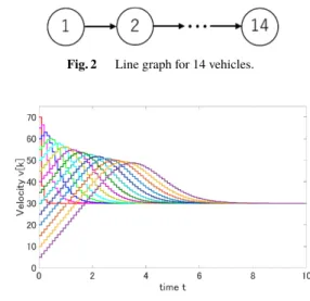
Fig. 2 Line graph for 14 vehicles.
Fig. 3 Consensus by normal pinning control.
pinning control to the vehicle platoon whose graph structure is shown in Fig. 2, and compare their responses. Here, the normal pinning control is a control method in which control input (17) is applied and the pinning agent is fixed. The same parameters are used in both cases. In addition, we compare the responses of the switched pinning control withq = 0, 0.01, 0.1, 1, 10, 100. The simulation time is 10 [s] and the sampling timeTs is 0.1 [s]. Figure 3 shows the responses of the normal pinning control. Figure 4 and Fig. 5 show the responses of the switched pinning control with q = 0 andq =1, respectively. Table 1 shows the settling timeTst and the number of switching Nsw. The settling time is the time when all the vehicles converge to their consensus value within 1% error.
The comparison of Fig. 3 and Fig. 4 shows that the switched pinning control converges earlier than the normal pinning control. In Fig. 4, since there is no penalty term in the cost function, the switching of the mode continues to the end of the simulation. In Fig. 5, when the velocities of the vehicles converge to the target value, we see that the influ- ence of the penalty term becomes gradually larger, and the mode finally stops to mode 5. Moreover, Table 1 shows that the number of switching becomes less, and the convergence speed becomes slower asqgets larger.
Here, we have to be careful with the calculation time.
The calculation time of the switched pinning control algo- rithm becomes longer than the normal pinning control due to solving the MIQP problem every step.
4.2 Velocity Control for Merging Maneuver
In this section, we simulate how 15 vehicles travel on a circular course shown in Fig. 6. The length of this circuit is 1,600 [m], and target traveling velocities are 50 [m/s], 40 [m/s], 60 [m/s], and 30 [m/s] for every 400 [m]. Each vehicle platoon formed on the course is given the target velocity according to its leader position. Each vehicle is traveling at different initial velocities att =0. The ex-device sends the target velocity to the pinning agent and converges
Fig. 4 Consensus by switched pinning control (q=0).
Fig. 5 Consensus by switched pinning control (q=1).
platoons to each target velocity quickly. In this experiment, the ex-device does not demand the platoon formation. The sampling timeTsis 0.05 [s].
Under these conditions, we apply the normal pinning control, and the switched pinning control. The time re- sponses of each method are shown in Fig. 7 and Fig. 8. Each
Table 1 Settling timeTs tand number of switchingNsw.
Fig. 6 Circle graph of 15 vehicles.
figure has the position, velocity, and mode responses.
In the case of the normal pinning control, when the simulation starts, three platoons are formed according to the observed inter-vehicular distances. In this case, only a vehicle platoon involving the pinning agent converges to the target value, and the other platoons converge to the initial velocity of the leader. It is because the pinning agent is pinned to the initial pinning agent. Moreover, when the distance between the two platoons is smaller thanxdaround t =10 [s], they do not merge because the Graph Laplacian is not updated.
In the case of the switched pinning control, when the simulation starts, three platoons are formed as same as the normal pinning control method. All the platoons are con- verged to the target velocities by switching the pinning agent.
Furthermore, we can see that the mode is fixed to the most active one in the steady-state. Moreover, when the distance between the two platoons is smaller thanxdaroundt=4 [s], two platoons merge together because the ex-device updates the Graph Laplacian. Also, we see that the third method con- verges the mode to a certain mode as the platoons consensus the velocities.
From this experiment, we have confirmed that our pro- posed algorithm allows the platoons to merge according to the distributed decision of each vehicle.
4.3 Velocity Control for Splitting Maneuver
In this section, we also simulate how 15 vehicles travel on the circular course shown in Fig. 6. The length of the course is 2,000 [m]. Each vehicle platoon formed on the course is given the target velocity according to its leader position or the formation demand from the ex-device. The target traveling velocities of the leaders in (40) are
Fig. 7 Normal pinning control in Sect. 4.2.
Vr i =
10+5(15−i) 0≤xi[k]<1000
80 1000≤xi[k]<2000. (49) Each vehicle is traveling at different initial velocities at t =0. In this experiment, the ex-device demands platoon formations. The formation demand is that the vehicles form small platoons when some of them go through the position x=0. Each platoon has two vehicles. Sampling timeTsis 0.05 [s].
Under these conditions, we apply the switched pinning control. The time responses are shown in Fig. 9. This figure has the position, velocity, and mode responses.
The all initial positions of 15 vehicles are within 1000≤ xi[k] < 2000. Also, the distances to the vehicle ahead of all vehicles are less than or equal toxdexcept for the leader.
Therefore, when the simulation starts, a large platoon with 15 vehicles is formed and travels at 80 [m/s].
When vehicle a1 and vehicle a2 go through x = 0, they form a small platoon by the formation demand from the ex-device, and from vehicle a3 to vehicle a15 form a large platoon. In this way, every time when two vehicles go throughx=0, some small platoons are formed. This experi- ment shows that the proposed method supports the ex-device
Fig. 8 Switched pinning control in Sect. 4.2.
to group vehicles depending on the formation demand.
Through Sects. 4.1 to 4.3, we can see the merging and splitting maneuver of the platoons aroundt=4 of Fig. 8(b) and aftert = 6 of Fig. 9(b), respectively. Therefore, these experiments show that it is good to switch pinning agents rather than to fix pinning agents for the merging and splitting maneuver.
5. Conclusion
In this paper, we have proposed a velocity control algorithm for merging and splitting maneuvers of the vehicle platoons using pinning control and MPC strategy. First of all, we have introduced the method to improve the convergence speed by switching the pinning agents. The method enables us to control multiple platoons. Second, we have proposed the adaptive platoon formation algorithm to update the Graph Laplacian. As the solution to the chattering problem due to the first method, we have introduced the cost function setting to attenuate the switching of the pinning agents in which the switching operation is penalized.
The numerical experiment in Sect. 4.1 shows the im- provement of the convergence speed. In Sect. 4.2, we also have confirmed the quick convergence to each target velocity
Fig. 9 Switched pinning control in Sect. 4.3.
of each group, the dynamic formation of vehicle platoons, and the merging of the platoons. In Sect. 4.3, we confirm the splitting maneuver due to the formation demand from the ex-device.
The platoon formation algorithm is based on MIQP, and then we have to pay attention to its computational load. The key idea is to construct an algorithm focused on the structure of the optimization problem [16]. Also, the vehicles of this paper have the same characteristics. Our future work is an application for different vehicles. Also, in this paper, when the ex-device demands the platoon formation, it is necessary to send external adjacency vectordex to the all vehicles. Therefore, the second future work is to consider the transmission range ofdex.
This paper is funded by JSPS KAKENHI Grant Number JP19H02158, JP19K04444, JP19H02163, and JP17H06293.
References
[1] S. Sabau, C. Oara, S. Warnick, and A. Jadbabaie, “Optimal dis- tributed control for platooning via sparse coprime factorizations,”
American Control Conference, pp.2591–2598, Boston, USA, July 2016.
[2] M. Torrent-Moreno, J. Mittag, P. Santi, and H. Hartenstein, “Ve- hicle to vehicle communication: Fair transmit power control for
safety critical information,” IEEE Trans. Veh. Technol., vol.58, no.7, pp.3684–3703, Sept. 2009.
[3] Y. Li, W. Chen, S. Peeta, and Y. Wang, “Platoon control of under V2X communications: Design and experiments,” IEEE Trans. Intell.
Transp. Syst., pp.1–12, April 2019.
[4] S. Yan, J.-S. Wang, J.-L. Wang, “Coordinated control of vehicle lane change and speed at intersection under V2X,” 3rd International Con- ference on Mechanical, Control and Computer Engineering, pp.69–
73, Huhhot Inner Mongolia, China, Sept. 2018.
[5] S. Azuma, M. Nagahara, H. Ishii, N. Hayashi, K. Sakurama, and K. Hatanaka, Control of Multi-Agent Systems, Corona Publishing, Japan, 2015.
[6] J. Qin, Q. Ma, Y. Shi, and L. Wang, “Recent advances in consensus of multi-agent systems: A brief survey,” IEEE Trans. Ind. Electron., vol.64, no.6, pp.4972–4983, Feb. 2017.
[7] D. Xu, A. Sakaguchi, and T. Ushio, “Stability analysis of pinning con- sensus control of discrete-time multi-agent systems,” IEICE Trans.
Fundamentals (Japanese Edition), vol.J101-A, no.7, pp.189–195, July 2018.
[8] A. Sakaguchi and T. Ushio, “Consensus speed of multi-agent systems via pinning control,” IEICE Trans. Information and Communication Engineers (Japanese Edition), vol.J100-A, no.7, pp.229–302, July 2017.
[9] W. Yang, Y. Wang, X. Wang, and H. Shi, “Optimal controlled nodes selection for fast consensus,” Asian J. Control, vol.18, no.3, pp.932–
944, May 2016.
[10] J. Imura, S. Azuma, and I. Masubuchi, Control of Hybrid Systems, Corona Publishing, Japan, 2014.
[11] A. Bemporad and M. Morari, “Control of systems integrating logic, dynamics, and constraints,” Automatica, vol.35, no.3, pp.407–427, March 1999.
[12] T. Ikeda and K. Kashima, “Sparsity-constrained controllability max- imization with application to time-varying control node selection,”
IEEE Control Syst. Lett., vol.2, no.3, pp.321–326, July 2018.
[13] K. Kobayashi, “Predictive pinning control with communication de- lays for consensus of multi-agent system,” IEICE Trans. Fundamen- tals, vol.E102-A, no.2, pp.359–364, Feb. 2019.
[14] C.E. Garcfa, D.M. Prett, and M. Morari, “Model predictive control:
Theory and practice — A survey,” Automatica, vol.25, no.3, pp.335–
348, May 1989.
[15] D. Swaroop and J.K. Hedrick, “String stability of interconnected systems,” IEEE Trans. Autom. Control, vol.41, no.3, pp.349–357, 1996.
[16] Y. Nagatain, K. Sawada, and S. Shin, “Self-triggered optimal control based on path search algorithm,” SICE J. Control, Measurement, and System Integration, vol.12, no.3, pp.85–93, May 2019.
Takuma Wakasa received the B.E. in mechanical engineering from the University of Electro-Communications, Tokyo, Japan, in 2019. He is currently pursuing the M.E. degree at the University of Electro-Communications.
His research interests include the control theory of multi-agent systems.
Yoshiki Nagatani received the B.E. degree in mechanical engineering from the University of Electro-Communications, Tokyo, Japan, in 2017. He is currently pursuing the M.E. degree at the University of Electro-Communications.
His research interests include the theory of net- worked control, especially self-triggered and event-triggered control.
Kenji Sawada received his Ph.D. degrees in engineering in 2009 from Osaka University. He is an Associate Professor in Info-Powered En- ergy System Research Center, The University of Electro-Communications, Japan. He is also an advisor of Control System Security Center since 2016. He received Outstanding Paper Awards from FA Foundation, Fluid Power Technology Promotion foundation, and JSME in 2015, 2018, and 2018. His research interests include con- trol theory of cyber-physical system and control system security. He is a member of SICE, ISCIE, IEEJ, JSME, IEEE.
Seiichi Shin received D.E. in 1987 from University of Tokyo. Since 2006, He is a profes- sor of the University of Electro-Communications through the University of Tokyo and the Univer- sity of Tsukuba. He is also the president of Control System Security Center since 2012. He received Outstanding Paper Awards from SICE in 1991, 1992, 1993, and 1998 including the Takeda Prize. He received a Minister of Econ- omy, Trade and Industry Award in 2018. He is interesting in control theory and its application.


![Fig. 7 Normal pinning control in Sect. 4.2. V r i = 10 + 5(15 − i) 0 ≤ x i [k] < 1000801000≤xi[k]< 2000](https://thumb-ap.123doks.com/thumbv2/123deta/5633453.1501407/9.892.508.781.107.647/fig-normal-pinning-control-in-sect-v-lt.webp)

