Algorithm of Smart Whistle with DSP and Accelerometer
journal or
publication title
福井大学工学部研究報告
volume 50
number 2
page range 213‑216
year 2002‑09
URL http://hdl.handle.net/10098/3250
Mem. Fac. Eng. Fukui Univ., Vol. SO, No.2 (September 2002) 213
Algorithm of Smart Whistle with DSP and Accelerometer
IDtosbi NISHI- and Tetsuma
SAKURAI··
(Received August 28, 2002)
We have developed an alarm system for the handicapped and the parents who bring up little children. This system consists of a TMX3 20VC5402 Digital Signal Processor (DSP), an accelerometer, a sounder and a battery, and is named "Smart Whistle". The Smart Whistle is beforehand given information of space data and alann points by users.
The features of Smart Whistle are as follows: First is what information of supporting space exists in the DSP memory. The system can judge the present place faster by the high performance DSP. Second is to use the accelerometer. This system can revise value between sensor inputs and space information the memory. This makes input interface simpler. Third, this system composes basic figures that are rectangles and right triangles to express the shape of arbitrary space. A complicated figure like concave express as sets of them. Therefore, it needs only to repeat simple calculations to know the present room.
It is possible to realize the 'compact system, because DSP is the center of the system.
Key Words: Smart Whistle, DSP, Support System, Accelerometer
1. Support System
Some action support systems have already developed.
The feature of these systems is as follows: First, objects of systems get detailed support information such as present position and surroundings. Second, the scale of the system composition is too big. For example, Personal Handy Phone System (PHS) communication offices, server to store support information, etc. Third, attention about an individual privacy is need. Because as portable system becomes smaller and smaller, a stranger can hides in
someon~'s
things to observe his or her behavior [1] .From these considerations, we develop new support system with DSP. This system is named "Smart Whistle."
• Information Engineering Course, Graduate School of Engineering
•• Fiber Amenity Engineering Course, Graduate School of Engineering
2. The Feature of Smart Whisde 2.1 Limitation Support Space
If the system supports big ar~ it needs big and complex composition. So, Smart Whistle supports small area. For example, an old people's home, facilities for handicapped, etc. The scale of total system reduced greatly with this idea.
2.2 Telling Caution by Alarm
Smart Whistle give the alarm to tell caution the supporter when the object of the support is in the edge of the space, it doesn't give detailed information like present position and conditions. The supported person can also hear this alarm because the alarm is made in the system (Cf. Fig. 1). Therefore, this system is not used for the purpose that a strang~ invades someone's privacy like movement observation.
2.3 Compact and High Cost Performance
It is important that the portable system is compact and light. Especially, in this system, cost performance is also big point because this is developed for persons based on daily life. Thus, to use DSP is very effective.
214
Suppoter \
PIPIP~
Object
Fig. 1 The Appearance of Operating Smart Whistle
3. The Configuration of Smart Whistle The system configuration is shown Fig. 2.
3.1 DSP Starter Kit (DSK) Board
The prototype system uses the DSK board that has TMX320VC5402 DSP. This DSP is so small that it is no problem to carry the system.
3.2 Accelerometer
Smart Whistle uses an accelerometer as input device.
This sensor can measure acceleration 40 times in a second. The prototype system connects accelerometer to board by a RS-232C interface. This sensor can operate in a body and connects to DSP directly without RS-232C interface in practical use, so it makes no obstacle for whole system scale [2] .
3.3 Sounder
The General speaker is used as sounder that makes alarm to supporter. Sounder connect with audio interface on DSK board. The frequency of alarm is decided from the room that system exist. So, supporter can know the object position from sound height.
Accelerometer
I 0 I '"
I I
SounderI I
I ~:
L _ _ _ _ _ _ Host Computer (Connect when setup rooms)
Fig. 2 The Configuration of Smart Whistle
3.4 Battery
A battery supplies the system with electricity.
3.5 Host Computer
Supporters use host computer when they define support area. When the system operates, it isn't connected, so host computer doesn't give the influence on total scale of system. Users define rooms with keyboard, and then host makes a file about support space into itself
4. Algorithm of Smart Whistle
System Start
Setup Support Space
Fig. 3 System Flow
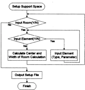
4.1 Setup Support Space
Users define space supported by the system. Space is composed of some rooms. And these rooms are composed of some elements. Elements are rectangle, right triangles and circles. Users input parameters of these figures. Conjunction these elements become one room (Cf Fig. 4). So, it is possible to define room freely.
The room center is axis average of each elements center and area. And circles are divided rectangles and right triangles. In other words, all rooms are expressed two element types, so the number of elements is increasing, but processor only repeats simple calculation again and again to judge where the object is. The data structure like this matches with
nsp.
Users designate initial position of the system at same time. These definitions are written to a file in host computer.nsp
reads this file (Cf. Fig. 5).4.2 Reset Position
Before starting operation, it is necessary to init present position. User carries Smart Whistle system to start
position defined beforehand and does reset action. It is designated and unique action, like shaking up and down quickly.
nsp
resets position when it senses this action. Itis effective for simple system to use accelerometer, do not use extra switch.
Setting Elements
Conjunction &
Calculation Center
One Room
Fig. 4 The Way of Making One Room from Elements
Setup Support Space
Fig. 5 Flow of Setup Supporting Space 4.3 Operation
The system shifts to operation mode at the same time when reset is performed. Operation means that the system measures position of the person who has Smart Whistle and result causes alarm (Cf. Fig. 6).
The system takes acceleration in when reception interruption of 'serial communication. The time interval that ,acceleration is taken in is important. If this interval is irregular, velocity and position are incalculable only by simple addition and subtraction.
Fig. 6 Flow from Reset to Operation
However, accelerometer doesn't measure its own timing. It measure when it receive a demand from DSK board. From this design, if the measurement demand by the side of a board is transmitted for every fixed time, the processor gets acceleration the same. Therefore, the task, which transmits a measurement demand, is started by timer interruption of a fixed time interval.
The inside of the task started by reception interruption, i,e., an acceleration acquisition task, is simplified as much as possible. The interruption process must finish for a'short time, and prepare for the next interruption L3J .
The relation between distance and alarm amplitude is made to become sound able to hear at the end of the range, which can be acted. A special judgment is not performed because the determination of amplitude is simplified by making it into the functi<:>n of distance.
The state of this operation continues, unless the initial configuration of system, such a setup of space, reset, is performed again.
5. Development of Smart Whistle S.l Program in Bost Computer
A program that is used to setup space in host is made by C++ language. The information that user is setting space is located into heap memory in host to be able to input many rooms. And the structure of. space information is as follow Table 1 and Table 2 Some data that DSP needs save to setup file.
Variable (XO,YO)
~x,Wy) Ne
*ep
*rp
Variable
s
(x,y) Type p1 p2
*next
Table 1 Structure of Room Data Content
Center axis of room Width and Height
The Number of Elements composing Room Pointer to First Elements
Pointer to Next Room
Table 2 Structure of Element Data Content
Area of Element Basis axis of Element
Type (Rectangle or Right triangle) First Parameter
Second Parameter Pointer to Next Element
216
5.2 Program in DSP
A program in DSP was developed in tool attached Starter Kit. The information of supporting space is also located in heap memory like host. Thus, processor can use memory flexible.
The way to calculate position from acceleration is repeat simple addition. First, velocity is calculated from discrete-time acceleration data. Next, position is decided from this velocity. This way is able because discrete-time interval is constant (Cf. Fig. 7).
'---I._'"!----.~!-.... ~.!I---._'"!-••
ConItant InIeMII
Fig. 7 Procedure about Computing Position Accelerometer can measure 40 times in a minute. If this capacity is used full, reception interruption occurs every 25ms. Processor needs IOns for one instruction because processing capacity of DSP is 100MIPS [4] .
Therefore, DSP can process 250,000 instructions between interruptions. Tasks running between interruptions are judging the room that the object is in and calculation frequency and amplitude of alarm.
An
of these instructions are within this range. So, it is no problem if accelerometer is operated 40 times in a second, full capacity.Finally, it is important to program and data size. DSP program size is estimated about 30K words at last. And the case of data, approximately 10K words needs if 100 rooms and 500 elements are set. Therefore, DSP's memory is enough for this system.
6. Conclusion
This time, fundamentals of system design and algorithm for Smart Whistle are completed. After this, we realize engineering samples according to these plans and see the movement. Then, we consider about expansion to three-dimensional support system to become what can correspond to real building.
References
[1] T. Sakurai, T. Hagino, Y. Suzuki and Y. Nishino: J.
IEICE, 82-4, 397-403 (1999)
[2] Texas Instruments Incorporated: Users Manual, Texas Instruments Incorporated, 5-1 (1996)
[3] K. Seya: DSP C Programming Nyuumon, Gijutsu .. Hyoron Co., Ltd. (2000)
[4] Texas Instruments Incorporated: Reference Set Volume. I, Texas Instruments Incorporated, 1-8 (1998)