Switched Uses of a Bidirectional Microphone as a Microphone and Sensors with High Gain and Wide Frequency Range
著者 SHIONOYA Toru
著者別名 塩野谷 暢
page range 1‑23
year 2015‑03‑24
学位授与年月日 2015‑03‑24
学位名 修士(工学)
学位授与機関 法政大学 (Hosei University)
URL http://hdl.handle.net/10114/11784
修士論文
Switched Uses of a Bidirectional Microphone as a Microphone and Sensors with High Gain and Wide
Frequency Range
2014 年度
理工学研究科 システム工学専攻 13R6108
塩野谷 暢
指導教員 渡辺嘉二郎 教授
2
Abstract
Mass-produced bidirectional microphones have attractive characteristics.
They work as a microphone as well as a sensor with high gain over a wide frequency range; they are also highly reliable and economical. We present novel multiple functional uses of the microphones. A mathematical model for explaining the directivity and high-pass-filtering characteristics of bidirectional microphones was presented. Based on the model, the characteristics of the microphone were investigated, and a novel use for the microphone as a sensor with a wide frequency range was presented. In this study, applications for using the microphone as a security sensor, an environment sensor, and a human biosensor were introduced. The mathematical model was validated through experiments, and the feasibility of the abovementioned applications for security monitoring, environment monitoring, and the biosignal monitoring were examined through experiments.
Keywords
Bidirectional Microphone, low-frequency,
mathematical model, frequency response
3
Contents
I. INTRODUCTION
II. MATHEMATICAL MODEL OF A BIDIRECTIONAL ELECTRIC CONDENSER MICROPHONE
A. Characteristics of Bidirectional Microphone
B. Characteristics of Omnidirectional Microphone and Sensors
C. Change in Characteristics of the Bidirectional Microphone by Switching the Cover of the Rear Port Open and Close
III. APPLICATIONS A. Applications
B. Use as a Mobile Phone Microphone IV. EXPERIMENTAL VERIFICATIONS
A. Characteristics as a Bidirectional Microphone and Low-frequency Microphone or Sensors
B. Security Application
C. Ultra-low Frequency Sound Measurement from Windmill D. Detection of pulsation
V. DISCUSSION
VI. CONCLUSION
REFERENCES
4
I. INTRODUCTION
Microphones have been used globally as an acoustic sensor in our daily lives. They are used in telephones, mobile phones, interphones, transceivers, computers, and various acoustic devices.
Microphones with an audio amplifier can detect changes in pressure with an amplitude of 2 × 10⁻⁵ Pa in the frequency range of 20 Hz to 20 kHz, which corresponds to the frequency range that is sensitive of the human auditory system. They are pressure sensors with high sensitivity.
Further, mass-produced microphones are highly reliability and economical. Various microphone applications have been investigated. Major recent applications include the localization of a sound source by a microphone array or distributed microphone pairs. Reference [1] summarized previous studies. These studies basically examine the time delay of the sound wave arriving to each of the spatially distributed microphone in the array. Directivity control of the microphone system depends on the characteristics of the time delay. Some microphone systems use multiple microphones to realize narrow-angle directivity [2]. However, even in a single microphone, the directivity can be controlled by appropriately setting single or multiple sound pressure detecting ports on the pressure detecting plate. Microphone can be an omnidirectional microphone, unidirectional microphone, or bidirectional microphone.
In this study, we focus on a bidirectional microphone that has two pressure detecting ports: one port is usually on the front side, and the other is on the rear side. We present the multifunctional uses of the bidirectional microphone, not only in its original function as a microphone but also as a high-gain sensor with a wide frequency range. They microphone can function as a sensor by simply opening or closing one of the ports. The potential of microphones to be used as sensors for various applications has been investigated by authors [3]-[9]. We used the microphone as a pressure sensor in a pneumatic biosignal bed sensing system for a person lying in bed [3], [4], as a multivariable detecting sensor for detecting symptoms of security events [5], [6], as a sensor to find hidden people in automobiles [7], and as a sensor element in ubiquitous health monitoring systems [8], [9]. In the studies above, we simply used a low-frequency microphone realized by a unidirectional microphone.
In this study, we employ a new bidirectional microphone for the same purposes above, but we can alternate its use between a microphone or sensor depending on the opening/closing of the ports. To enable a bidirectional microphone to be used for multiple functions, we must first clarify what happens in the microphone and study its characteristics when it is used for its original purpose—i.e., the case when the two ports of the microphone are open—as well as when it is used as a sensor—i.e., the case when one of the ports is closed. In this paper, we describe a mathematical model using transfer functions for explaining what happens in the microphone in both cases by using a lumped mass model, as previously studied in the literature [10], [11]. Further, we present novel applications along with the conventional applications.
5
II. MATHEMATICAL MODEL OF A BIDIRECTIONAL ELECTRIC CONDENSER MICROPHONE
A. Characteristics of Bidirectional Microphone
<< Structure of a bidirectional microphone>>
Figure 1 shows the structure of the bidirectional microphone. The structural feature of the microphone is that it has two pressure detecting ports: one is usually on the front side, and the other is on the rear side. This structure determines the fundamental characteristics of the microphone. The manner in which the pressure wave propagates to the microphone and the physical variables and constants associated with the phenomenon occurring in the microphone are described in (i) to (xi) in Figure 1.
L q
L cosq
(i)
(ii) (iii)
(iv)
(v) (vi) (vii) (viii) (ix)
(x) (xi)
Source acoustic pressure is a plane sinusoidal wave p(t) with frequency f, amplitude P, and propagation direction q from the axis of the microphone in air with sound velocity C0. The time t is the propagation time from the sound source to the microphone front port in (iii).
(i)
Bidirectional electric condenser microphone with length L.
(ii)
Front port to receive front pressure pf (t).
(iii)
Front chamber (iv)
Pressure detecting electret film with perpetual charge Q, cross-sectional area A, mass m, spring constant k, and damping coefficient d. The film moves with displacement x due to the difference in front pressure pf (t) and rear pressure pr (t), given as Dp(t) = pf (t) - pr (t).
(v)
Electrode to realize capacitance between electret film (v) and itself. The dielectric constant of air between them is e and the capacitance is C from which current flows into the input of the FET amplifier (ix).
(vi)
Rear chamber.
Rear port to receive rear pressure pr (t).
Flexible air sealing cover deformed by changing the external force, and the pressure in the rear chamber (vii) due to the force is pE (t).
FET amplifier with input electric resistance and gain G.
The input voltage is e’(t), and the output voltage is e(t).
Output terminal of the output of the FET amplifier (ix).
The voltage is e(t).
(vii) (viii) (ix) (x)
(xi)
Fig.1 Structure and elements of bidirectional electric condenser microphone and associated variables and constant.
6
<<Pressures at the front port and rear port>>
The source acoustic pressure 𝑝(𝑡) can be described from description (i) in Figure 1 as follows:
𝑝(𝑡) = 𝑃 sin{2π𝑓(𝑡 + 𝜏)}
(1)The audio wavelength is sufficiently long in comparison to the length of the microphone L in (ii).
Thus, the frequency f satisfies the following condition:
𝑓 ≪
𝐶𝐿𝑜(2)
For example, suppose 𝐿 = 5 × 10⁻³m, which is a standard length of microphones, then the frequency is as follows:
𝑓 = 340 m s ⁄
5 × 10
−3m = 68 kHz
which is higher than the maximum audio frequency. For applications when the frequency is less than the maximum frequency, such as 1 kHz or 100 Hz, eq. (2) can be completely satisfied. The time taken for sound to travel from the acoustic pressure source in (i) to the front port (iii) is and the time taken to travel to the rear port (viii) must be
𝜏 +
𝐿cos𝜃𝐶𝑜 because the rear port is located 𝐿cos𝜃 away from the front port, as shown in Figure 1, and the pressures at the front port at the rear port can be described respectively as follows;
𝑝
𝑓(𝑡) = 𝑃 sin{2𝜋𝑓(𝑡 + 𝜏 − 𝜏)} = 𝑃sin(2𝜋𝑓𝑡) (3)
𝑝
𝑟(𝑡) = 𝑃 sin [2𝜋𝑓 {𝑡 + 𝜏 − (𝜏 + 𝐿cos𝜃 𝐶
𝑜)}]
= 𝑃 sin {2𝜋𝑓 (𝑡 −
𝐿cos𝜃𝐶𝑜
)} (4)
The pressure at the rear port can be written using the addition theorem of trigonometric functions as follow:
𝑝
𝑟(𝑡) = 𝑃cos (2𝜋𝑓
𝐿cos𝜃𝐶𝑜
) ∙ sin(2𝜋𝑓𝑡) − 𝑃 sin (2𝜋𝑓
𝐿cos𝜃𝐶𝑜
) ∙ cos (2𝜋𝑓𝑡) (5)
7
From eq. (2), 𝑓
𝐶𝐿𝑜
≪ 1 , then 2π𝑓
𝐿cos𝜃𝐶𝑜
≅ 0 , and thus cos (2𝜋𝑓
𝐿cos𝜃𝐶𝑜
) ≅ 1 and sin {2𝜋𝑓
𝐿cos𝜃𝐶𝑜
} ≅ 2𝜋𝑓
𝐿cos𝜃𝐶𝑜
.
Consequently, the pressure at the rear port can be described as follows:
𝑝
𝑟(𝑡) = 𝑃 sin(2𝜋𝑓𝑡) − 𝑃2𝜋𝑓
𝐿cos𝜃𝐶𝑜
cos (2𝜋𝑓𝑡) (6)
The pressure at the front port 𝑝𝑓(𝑡) and that at rear port 𝑝𝑟(𝑡) act in a differential manner to the electret film (v), and the differential pressure can be obtained from eq. (3) and eq. (6) as follows:
∆𝑝(𝑡) = 𝑝
𝑓(𝑡) − 𝑝
𝑟(𝑡) = 𝑃2𝜋𝑓 𝐿cos𝜃
𝐶
𝑜cos(2𝜋𝑓𝑡)
=
𝐿cos𝜃𝐶𝑜
∙
𝑑𝑝𝑑𝑡𝑓(𝑡)=
𝐿cos𝜃𝐶𝑜
∙
𝑑𝑝(𝑡−𝜏)𝑑𝑡 (7)<<Dynamics of the electret film>>
The dynamics of the electret film modeled by a lumped mass can be described from the equation of motion for the electret film as follows:
𝑚
𝑑2𝑑𝑡𝑥(𝑡)2+ 𝑑
𝑑𝑥(𝑡)𝑑𝑡+ 𝑘𝑥(𝑡) = 𝐴∆𝑝(𝑡) (8)
<<Output voltage from capacitor owing to displacement 𝑥(𝑡)>>
From the physics of static electricity, the voltage between the electret film (v) and the electrode (vi) is given as a function of displacement 𝑥(𝑡) in eq. (8) as follows:
𝑣(𝑡) = −
𝑄𝜀𝐴
𝑥(𝑡) (9)
8
<<Electric circuit>>
From the electric circuit of the capacitor to the input of the FET amplifier (ix), we have the following circuit equation:
𝑟𝑖(t) +
𝐶1∫ 𝑖(𝑡)𝑑𝑡 = 𝑣(𝑡)
0𝑡 (10)𝑒
′(𝑡) = 𝑟𝑖(𝑡)
(11)The output voltage is given by
𝑒(𝑡) = −𝐺𝑒′(𝑡)
(12)Eqs. (7)–(12) lead to a transfer function of the output voltage 𝑒(𝑡) with respect to the pressure 𝑝(𝑡), as shown in Figure 2.
Co
L cos
q
s -st
e
(sCr)QG
(ms2 + ds + k)(1+ sCr)
p D p e e
Fig.2 Transfer function of output voltage e(t) with respect to source acoustic pressure p(t).
Note in the transfer function in Figure 2, the gain 𝐿cos𝜃
𝐶𝑜
𝑠
shows the characteristics of directivity of the microphone. The transfer function is a function of the sound propagation direction to the microphone 𝜃. Further, the gain includes the temporal differential characteristic given by the differential elements ≡
𝑑𝑡𝑑 and the gain 𝐿𝐶𝑜, which considerably reduces the gain in the low-frequency range.
9
C. Characteristics of Omnidirectional Microphone and Sensors
Consider the situation when the rear port is closed by cover (x) and the rear chamber (vii) in Figure 1 is air-sealed. The source acoustic pressure will be able to arrive at the front port but it will not be able to arrive at the rear chamber, which eliminates the function of directivity and only the pressure arriving at the front port acts on the electret film. When the flexible cover is pushed by an eternal vibratory force, the electret film is pushed to the front side by the pressure 𝑝𝐸(𝑡). The electret film is pushed to front side by the pressure 𝑝𝐸(𝑡). Then, the transfer function for the abovementioned situation can be described as shown in Figure 3.
-s t
e (sCr)
QG
(ms
2+ ds + k)(1+ sCr)
p + e e
-
p
EFig.3 Transfer function of output voltage e(t) with respect to source acoustic pressure p(t) and pressure pE (t) caused by external vibratory force pushing flexible cover of rear port.
Suppose, 𝑝𝐸(𝑡) = 0, i.e., no external vibratory force is acting in Figure 3, the bidirectional microphone acts as a omnidirectional high-gain, low-frequency microphone by eliminating the phenomena expressed by the gain 𝐿cos𝜃
𝐶𝑜
𝑠.
10
D. Change in Characteristics of the Bidirectional Microphone by Switching the Cover of the Rear Port Open and Close
As described in Sections A and B, the characteristics of the bidirectional microphone change simply change by opening or closing the rear cover. When the cover is open, the microphone acts as a bidirectional microphone, which is its original functionality; when the cover is closed, it becomes a low-frequency, high-gain omnidirectional microphone that detects pressure from the front port, as well as becomes a highly sensitive force vibration sensor that detects vibration through the flexible cover. Figure 4 shows the directivity characteristics and Figure 5 shows the frequency response for both cases derived by the transfer function in Figures 2 and 3.
0°
- 90° 90°
180°
Co
f high 2 p f L
Co 2 p f L
cos q
Bi-directional microphone when both ports are OPEN
Omnidirectional microphone when rear port is CLOSED and air sealed
Fig.4 Directivity characteristics of the microphone when the rear port is open or closed.
11
f 0dB
20 dB/dec
20 dB/dec
40 dB/dec 2 Cr
1
2 1 Hz
2 1
m k
Resonance frequency of the electlet film Cut-off frequency
by the electric circuit
20 log10 P
e
(a) (b)
20 log10 Co L 20 log10 k
(a) QG
(b)
Bidirectional microphone Remodeled omnidirectional
microphone
e cosq
p p p
Fig.5 Frequency response of the bidirectional microphone when the rear port is open or closed.
From Figures 4 and 5, the simple action of opening and closing of the cover (x) in Figure 1 of the rear port considerably changes the microphone characteristics. This simple action leads to a variety of novel and feasible applications of bidirectional microphones because such microphones are mass-produced and thus production lines are already developed for manufacturing such microphones.
Hence, these microphones are highly reliable and economical.
12 III. APPLICATIONS
Here, we introduce typical examples of applications using the bidirectional microphone.
A. Applications
The application of a low-frequency microphone has been investigated in previous studies [5] and [6], by using a low-frequency microphone. The proposed use of the bidirectional microphone can be used for similar purposes. Owing to the high gain in the low-frequency range, the microphone can detect a change in the low-frequency pressure caused by the opening or closing of a door in a building and can also detect the pressure change at approximately 4 Hz to 5 Hz by flames change in combustion by fire.
The feature of high gain in low frequencies, as used in a low-frequency microphone, allows the detection of low-frequency noise. Ultra-low frequency noises in our daily lives sometimes cause the suffering our nevus. For example, a windmill rotates at approximately 20 rpm, and if it has three blades, it generates a large noise of 1 Hz, which cannot be perceived by a human. However, the change in pressure pushes window glass, and hence, an audible sound is generated every 1 s continuously. Victims would like to know the cause of the sound. The low-frequency function of the microphone would help detect the cause of the sound. The conventional low-frequency anemometer does not have sufficient gain in the low-frequency range, but the proposed use of the microphone has sufficient gain even in the low-frequency range.
The detection of pulse waves of a subject in bed or those at the fingertip or carotid area is essential for health monitoring. This work was also carried out in previous studies [3], [4], [8], [9] and was referred to as the pneumatic method. In the previous work, we used a low-frequency microphone.
The use of the microphone as a low-frequency vibration sensor yields the same function as those in previous studies. If the flexible cover (x) in Figure 1 is touched softly by a fingertip or the carotid area, the microphone detects the low-frequency movement due to pulsation. If it is placed near the chest, it can detect the cardiac sound.
13 B. Use as a Mobile Phone Microphone
The abovementioned applications are effective when the microphone is mounted on a mobile phone or smartphone, as shown in Figure 6. The use of the microphone as a bidirectional microphone is effective when the microphone is used as an audio microphone. The directivity of the microphone reduces the environmental noise, but voice generated near the front port is detected with high gain. Further, as the distance L between the front port and rear port becomes longer than microphone itself, the gain increases (eq. (7)). The frequency response of the directional microphone at low frequencies is poor for detecting high-quality sound. However, in reality, the frequency range in the mobile phone or smartphone is limited to 500 Hz to 5 kHz, which can be covered by the microphone.
At midnight, when the mobile phone is charging, it can be used as a security event detecting system. For this, the rear port cover is closed, and it is allowed to work as a low-frequency, high-gain microphone, and, it can detect symptoms of security events as mentioned above.
When the flexible cover is softly touched by a fingertip or carotid area, the movement due to the blood pressure at the fingertip or the carotid area can be detected. Mobile phones or smartphones equipped with the microphone expands their applications to security and ubiquitous health monitoring.
Voice
Surround
noise cancel Low frequency
microphone to detect room door open and
pressure by fire Sliding cover is closed Door
open/close
Fire
Low frequency vibration to detect movement at fingertip
due to pulse Sliding cover to open
or close the rear port Rear side
Mobile phone
Bidirectional microphone Front side
Front port
Rear port
Fig.6 Applications by microphone mounted on mobile phones or smartphones.
14 IV. EXPERIMENTAL VERIFICATIONS
A. Characteristics as a Bidirectional Microphone and Low-frequency Microphone or Sensors
The microphone employed in the experiment is a standard bidirectional microphone EM-114 (Primo-Co Ltd ), which is a close talk microphone and has a small head-set of 10
L = 5 mm and with noise cancelation owing to the bidirectional characteristics. The specifications of the microphone are listed in Table I.
Table I.
SPECIFICATION OF THE MICROPHONE EM-114 USED THE EXPERIMENT
Directivity Bidirectional
Sensitivity −50 dB ± 3.5 dB at 1 kHz (0 dB = 1 V/Pa)
and 1 k load 2 V power supply Impedance 1 k ± 30% at 1 kHz and 1 k load
S/N ratio above 62 dB at 1 kHz Operating Voltage 2 V (from 1.1 V to 10 V) Current consumption 300 A
Weight 0.8 g
15
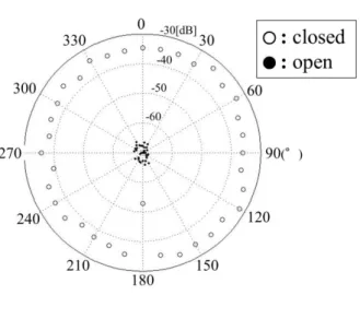
<<Directivity>>
Figure 7 shows the directivity at 100 Hz and 1 kHz for both cases, when the rear port is open or closed. When it is open, the microphone shows bidirectional characteristics with low gain. When it is closed, the microphone shows omnidirectional characteristics with high gain. Both characteristics are similar to the characteristics shown in Figure 4, which were derived theoretically.
(a) The outer circle shows the directivity when the rear port is closed, and small dual circles show the directivity when the port is open for the frequency of 100 Hz.
(b) The outer semi-circle shows the directivity when the rear port is closed, and medium dual circles show the directivity when the port is open for the frequency of 1 kHz
Fig.7 Directivity characteristics at 100 Hz and 1 kHz for both cases, when the rear port is open or closed.
16
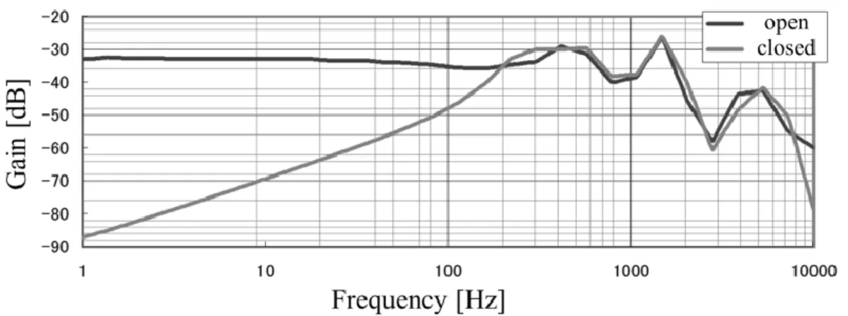
<<Frequency Response>>
Figure 8 shows the frequency responses for both cases, when the rear port is open or closed. When the rear port is open, i.e., a bidirectional microphone, the test sounds were fed from an angle of 0°.
When it is open, the gain in the frequency range 1 Hz to 100 Hz shows high-pass-filtering characteristics with +20 db/dec, which are differential characteristics, and the results show good agreement with those derived theoretically. On the other hand, when the rear port is closed, the frequency response in the range 1 Hz (or less than 1 Hz) to 100 Hz shows a flat gain, which corresponds to the gain 20log10|𝑄𝐺𝜖𝑘| shown in Figure 5. The cut-off frequency 2𝜋𝐶𝑟1 in Figure 5 is less than 1 Hz. At 1 Hz, the gain when the rear port is closed is 55 dB higher than that when the rear port is open.
Fig.8 Frequency responses for both cases, when the rear port is open or closed. The directivities and frequency responses show those theoretically predicted in Chapter II.
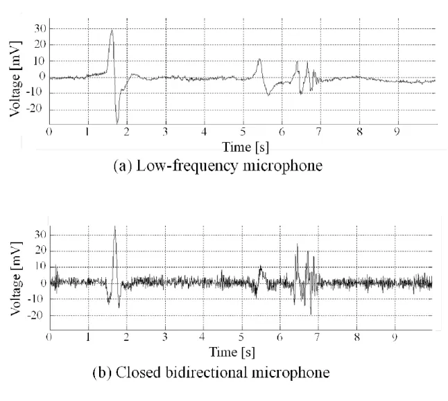
17 B. Security Application
Figure 9 shows the change in pressure when a door of 0.8 × 2.0 m2 of a room with a floor area of 77 m2 and 2.5 m height was open with an angular velocity of 90 deg./s and closed.
Fig.9 Changes in pressure when door is open. The upper graph shows the conventional low-frequency microphone. The lower graph shows the bidirectional microphone when the rear port is closed without an amplifier
18
C. Ultra-low Frequency Sound Measurement from Windmill
The ultra-low frequency from a windmill was measured by the microphone with a closed rear port.
The height to the center of the windmill from the ground was 64 m with three blades of length 35.5 m. The microphone was set in a closed, small, airtight house of 4.5 m length, 1.8 m width and
windmill. The rated power was 2000 kW, the rated maximum wind speed was 12.5 m/s, and the minimum wind speed was 2.5 m/s. Figure 10 shows the output voltage from the microphone without an amplifier, when the average speed of the windmill was 11 m/s and the revolution speed was 21 rpm. The pressure change occurs when a blade approaches the tower of the windmill, by generating negative pressure between the tower wall and blade. Because the mill has three blades, the frequency of the pressure change is 3×21 rpm60 s = 1.05 Hz. The spectrum in Figure 10 shows the conspicuous peak as a fundamental, as well as its higher components.
Fig.10 Ultra-low frequency pressure detected by the microphone when the rear port is closed.
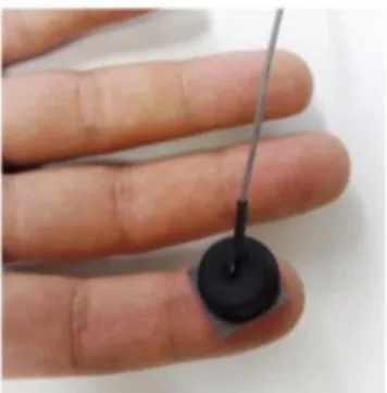
19 D. Detection of pulsation
Figure 11 shows the use of the microphone as a vibration sensor. The rear port of the microphone was affixed on a fingertip and the front port was open. The microphone works as a vibration sensor and detects pulsation due to blood flowing in the fingertip.
Fig.11 Detection of pulsation at a fingertip by using the bidirectional microphone as a vibration sensor.
20 V. DISCUSSION
We did not mount the microphone to mobile phones as shown in Figure 6 in this study. However, we clarified the characteristics and presented applications that can be realized when the microphone is mounted on a mobile phone. The interesting feature of the microphone is that a user can easily change its characteristics by opening or closing one of the ports. This opening/closing action yields novel fruitful applications of mobile phones and smartphones. This idea can be expanded to any audio system that employs microphones, and the audio system can be, for example, a security system, health monitoring system, and environmental monitoring system.
21
VI. CONCLUSION
This paper describes a mathematical model of a bidirectional microphone with two pressure ports.
Using the model, we clarify the characteristics of the bidirectional microphone as well as the omnidirectional microphone, which can be realized simply by closing one of the pressure ports. The directivities and frequency responses of the microphone used as a bidirectional and omnidirectional microphone obtained through experiments are in good agreement with the analytical results based on the model. Hence, the validity of the model was proven. The different uses of the microphone, i.e., both ports open use and one port closed change the characteristics of the microphone to a considerable extent. Switching from open to close can be easily realized by, for example, closing a port using a fingertip or by closing using a prepared cover. This opening/closing of a port of the microphone yields a variety of applications, especially when employed in mobile phones. When the microphone is used as an acoustic microphone, it is less noise sensitive to environments but more sensitive to voice. When one of the ports is covered, the microphone becomes a low-frequency, high-gain pressure sensor that can detect the pressure changes due to door opening and closing of a room or those due to fire flame. When one of the ports is closed by a fingertip, the microphone can detect the low-frequency vibration of the fingertip due to the pulsation of blood flow.
Further, the gain in the low frequency of the omnidirectional microphone is very high even in comparison with a common microphone; it can be used in environments of low-frequency pressure.
22
References
[1] L. Pei, L. Chen, G. Robert, J. Liu, H. Kuusniemi, Y. Chen, R. Chen, and S.
Söderholm, "Sound Positioning Using a Small-scale Linear Microphone Array," 2013 International Conference on Indoor Positioning and Indoor Navigation, 28-31st, p.7, 2013.
[2] T. Sugimoto, M. Iwaki, K. Ono, A. Ando, T. Ishii, K. Imanaga and Y. Chiba, "A Narrow-Angle Directional Microphone with Suppressed Rear Sensitivity," IEEE Transactions on Broadcasting, vol. 56, no. 1, pp. 92-97, 2010.
[3] K. Watanabe, T. Watanabe, H. Watanabe, H. Ando, T. Ishikawa, and K. Kobayashi,
"Noninvasive Measurement of Heartbeat, Respiration, Snoring and Body Movements of a Subject in Bed via a Pneumatic Method," IEEE Transactions on Biomedical Engineering, vol. 52, no. 12, pp. 2100-2107, 2005.
[4] T. Watanabe, and K. Watanabe, "Noncontact Method for Sleep Stage Estimation,"
IEEE Transactions on Biomedical Engineering, vol. 51, no. 10, pp. 1735-1748, 2004.
[5] T. Ishigaki, T. Higuchi, and K. Watanabe, "An Information Fusion-Based Multi-objective Security System with a Multiple-Input/Single-Output Sensor," IEEE Sensors Journal, vol. 7, no. 5, pp. 734-742, 2007.
[6] T. Ishigaki, T. Higuchi, and K. Watanabe, "A Multivariable Detection Device Based on a Capacitive Microphone and Its Application to Security," IEEE Transactions on Instrumentation and Measurement, vol. 59, no. 7, pp. 1955-1963, 2010.
[7] Y. Kurihara, and K. Watanabe, "Development of Sensing Device to Detect Persons Hiding in a Car," IEEE Sensors Journal, vol. 11, no. 9, pp. 1872-1878, 2010.
[8] K. Watanabe, Y. Kurihara, and H. Tanaka, "Ubiquitous Health Monitoring at Home – Sensing of Human Biosignals on Flooring, on Tatami Mat, in the Bathtub, and in the Lavatory," IEEE Sensors Journal, vol. 9, no. 12, pp. 1847-1855, 2009.
[9] K. Watanabe, Y. Kurihara, T. Nakamura, and H. Tanaka, "Design of a Low-Frequency Microphone for Mobile Phones and Its Application to Ubiquitous Medical and Healthcare Monitoring," IEEE, Sensors Journal, VOL.10, NO. 5, pp.
934-941, 2010.
[10] J. Silva, and T. Chau, "A Mathematical Model for Source Separation of MMG Signals Recorded With a Coupled Microphone-Accelerometer Sensor Pair," IEEE Transactions on Biomedical Engineering, vol. 52, no. 9, pp1498- 1501, 2005.
[11] R. Nadal-Guardia, A. M. Brosa, and A. Dehé, "AC Transfer Function of Electrostatic Capacitive Sensors Based on the 1-D Equivalent Model: Application to Silicon Microphones," Journal of Microelectromechanical Systems, vol. 12, no. 6, pp.
972-978, 2003.
23
謝辞
本研究を進めるにあたり,渡辺嘉二郎教授と小林一行教授には,手厚いご指導をして頂 き,大変お世話になりました.特に渡辺嘉二郎教授には研究を進める際に,何度も相談に 乗って頂き,計測方法の問題点や改善点など,多くのお力添えを頂きました.この場をお 借りして,心より感謝いたします.本当にありがとうございました. また,実験の際に協 力してくださった研究室の同期と後輩の皆さんに感謝します.
最後に,不自由なく大学に通わせて頂いた両親に深く感謝します.
塩野谷 暢
平成26年2月23日