Doctoral Thesis
Micro Manipulation
by Multiple Flows
Jean-Charles PELLETIER
Department of Mechanical Engineering and Intelligent Systems
March 2019
Micro Manipulation by Multiple Flows
Approved by Supervisory Committee:
Chair Person: Prof. Dr. Hisayuki AOYAMA
Member: Assoc. Prof. Dr. Chisato KANAMORI
Member: Prof. Dr. Aiguo MING
Member: Assoc. Prof. Dr. Tetsuo KAN
Member: Prof. Dr. Masafumi UCHIDA
Declaration of Authorship
I, Jean-Charles PELLETIER, declare that this thesis titled “Micro Manipulation by
Multiple Flows” and the work presented in it are my own. I confirm that:
This work was done wholly or mainly while in candidature for a research
degree at this University;
Where any part of this thesis has previously been submitted for a
degree or any other qualification at this University or any other
institution, this has been clearly stated;
Where I have consulted the published work of others, this is always
clearly attributed;
Where I have quoted from the work of others, the source is always
given. With the exception of such quotations, this thesis is entirely my
own work;
I have acknowledged all main sources of help;
Where the thesis is based on work done by myself jointly with others, I
have made clear exactly what was done by others and what I have
contributed myself.
論文の和文要旨
論文題目 Micro Manipulation by Multiple Flows
(複数の微小流を用いたマイクロマニピュレーション) 氏 名 Jean-Charles PELLETIER 本論文では、生体細胞などを対象とする新しいマイクロマニピュレーション 方法について論じている。マイクロマニピュレーションはマイクロナノ技術に おいて重要な要素であり、対象物のサイズや周辺環境、および精密な再現性や 応用はマイクロマニピュレーションの原理を選択する際、重要な要件である。 それぞれのマイクロマニピュレーション原理は必要な仕様や要求条件で選択さ れなければならず、本論文では流体中で 100μm から 1mm の対象物を機械的な 接触や熱などの損傷を与えずにマニピュレーションすることを目的としてい る。 従来の方法では機械的な接触や電磁気的な手法が用いられていたが、細胞に 潜在的な損傷を与える恐れがあった。ここではまず細胞等を対象とした従来の マイクロマニピュレーション方法についてその長所や短所について概観してい る。従来のマイクロマニピュレーションでは、操作する対象物のサイズや特 性、操作環境、外部刺激への耐性により、マニピュレーションシステムの規 模、使いやすさ、価格等が大きく変化する。このため対象物サイズを幅広く選 択でき、損傷を与えることなく簡単に操作できるマイクロマニピュレーション が望まれている。特に 100μm~1mm の対象物を低侵襲で扱う簡便なマイクロマ ニピュレーションは、バイオエンジニアリングや医療分野で幅広く応用可能で 必要とされている。本論文では提案している微小流による手法の意義や問題解 決の可能性について論じている。 本論文では、3 つの微小流を用いた細胞保持構成を基本構想とし、その保持、 位置決めの方法に関する原理や特徴について説明している。これまでにモデル や実験的手法により得られた保持、位置決めの重要なパラメータについて整理 し、より詳細なマニピュレーションシステム設計において必要とされるパラメ ータについて、またその相関関係について述べている。さらにこのシステム設 計を実現する上での問題点、例えば、対象物周辺の流れの挙動が不明であるこ と等、解決すべき課題について指摘している。これらを踏まえた上で、本論文 が論じる操作対象物のサイズや操作環境を設定し、100μm(人の皮膚細胞)か ら 1mm(単細胞生物)を対象とした液中でのマイクロマニピュレーションの必 要性と実現可能性を述べている。 本マイクロマニピュレーションの原理の可能性を確認するため、また、流れ の挙動が不明であるという問題を解決するために、化学反応を用いた微小流の
満たし、ノズルから対象物に向かって放出される液体をアルカリ性溶液とし、 pH 値に反応する試薬を用いてこれらが混合されることで変色する現象を利用し て流れの可視化を行っている。この予備実験の結果、この原理を用いる場合の 微小な物体周りの流れが確認されている。この可視化により層流や乱流を発生 させる条件や流速や対象物とノズル間距離、ノズル設置位置等の変化による対 象物周囲への流れの挙動が観察された。さらに 2 つのノズルを用いた可視化で はノズル間距離による流れの挙動変化を示し、モデル化とシステム設計要件に 関連するパラメータの重要性について述べている。 次に可視化実験で観察された対象物表面の流れと対象物との間の相互作用に ついてモデル化を行った。簡易力学的モデルでは微小な流れが球状の対象物表 面を流れる際に流れが接する領域での粘性力と圧力を考慮し、レイノルズ数 3 (対象物 100μm)~30(対象物 1mm)の層流環境と仮定している。このモデル を用いて対象物の動作をシミュレーションしている。対象物に対するノズル位 置や流量を変化させた時の対象物の挙動について述べている。実験では化学的 な可視化および予備実験などから概ね簡略化したモデルが適用できることを明 らかにしている。 次に実験について述べている。実験装置は対象物保持部、流量制御部とタン ク部、XYZ ステージから構成されている。流量制御部とタンク部はアルキメデス の原理を利用し、重力ポンプ方式としている。対象物保持部は、着脱式の 3 つ の微小ノズルと1つの可逆ポンプにより構成されており、内部には水が充填さ れている。可逆ポンプを用いて、対象物保持部下部の開口部から対象物(生体 細胞)をピックアップし、3 つのノズルから微小流を流して保持や位置決めを行 う。実験では 0.8mm~1.1mm の魚卵を吸引し、所定の位置に保持し、10μL から 30μL の流量変化に対して、精密に上下に 550μm の範囲で精密移動できること やその再現性について検証した。 結論では本論文をまとめ、今後の課題について議論している。システムの自 動化や再現性向上の具体的な方策について言及している。 本論文では単一の生体細胞などを対象とし、複数の微小流を用いた新しい原 理のマイクロマニピュレーションを提案し、簡易モデルと数値シミュレーショ ンおよび精密な実験によりその有効性を確認した。
English abstract
Thesis title Micro Manipulation by Multiple Flows
(複数の微小流を用いたマイクロマニピュレーション)
Author Jean-Charles Pelletier
The first chapter introduces the concerns of the micro scale and the recent
major developments in bio engineering. The general objectives behind the
development of the solution proposed and its assets are mentioned.
The second chapter is dedicated to the study of the micro manipulation
technologies commonly found and currently developed in laboratories. The
solutions presented are separated in different categories depending on the
physical principle used for the manipulation while their assets and drawbacks are
presented.
The third chapter presents the solution proposed. The idea behind the 3
micro-flows manipulation, the reason behind this technical choice to protect the
target and the technical concerns and choices are presented. The parameters
behind the optimization of the manipulator are presented.
The fourth chapter introduces the chemical tool used for the flow
visualization in the preliminary experiments. The use and performances of such
tool is explained and the results of the experiments are presented. These results
supported the creation of a simple model, presented in the chapter 5, and the
design of the system.
The fifth chapter presents the micro-physical concerns, the hypothesis used
and establishes the simple model used to express the stability of our configuration.
The model uses the regular equations of mechanics and fluid mechanics and the
observations of the flow-target interaction and motion. The displacement of the
target is then analytically determined and discussed through a series of
simulations.
The sixth chapter presents the system resulting from the conclusions of all
the previous chapters. The design of the general system, its structure and the
experimental setup. The experimental results for the manipulation, stability,
positioning and repeatability are presented. The achievements and limitations of
the system are discussed.
The seventh chapter concludes on the different aspect of the project, the
future works and key factors for further optimization.
Contents
Chapter 1 Introduction ... 11
1.1. The challenges of the micro world ... 11
1.2. The evolution of bio-engineering ... 12
1.3. Overview of the micro-manipulation: variety, specialization and needs ... 12
1.4. Outline of the thesis ... 14
Chapter 2 Micro manipulation technologies ... 17
2.1. Mechanical and direct contact strategies ... 18
2.2. Optical devices: optical and optoelectronic tweezers ... 20
2.3. Electrostatic forces: microelectronic sorting ... 22
2.4. Magnetic forces: magnetic marking of targeted elements ... 24
2.5. Microfluidic ... 24
2.6. Surface acoustic wave ... 26
2.7. Summary ... 27
Chapter 3 Principle of manipulation by 3 micro-flows ... 30
3.1. Range, objectives and technical concerns of the solution proposed ... 30
3.2. Holding configuration chosen and micro-flow manipulation principle ... 32
3.3. Previous works and discussion ... 35
Chapter 4 Chemical visualization for micro flows ... 37
4.1. The need for data collection and tools limitations ... 37
4.2. The innovative chemical visualization principle ... 38
4.4. Experimental results of the visualization ... 41
4.4.1. Visualization limits and saturation ... 41
4.4.2. Data collection ... 43
4.4.3. Flow stability and streamlines visualization ... 44
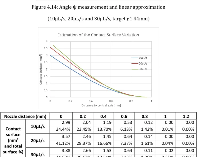
4.4.4. Nozzle distance ... 47
4.4.5. Contact surface variation ... 48
4.4.6. Dual flow visualization ... 55
4.5. Discussion ... 58
Chapter 5 Simple model of fluid dynamics ... 59
5.1. Hypothesis and discussion ... 59
5.1.1. Flow-target interaction – Pressure and viscosity ... 59
5.1.2. Wall-target interaction – Friction and roll-without-slide hypothesis ... 60
5.2. Parameters considered ... 61
5.2.1. Reynold number and scale issues ... 61
5.2.2. Parameters ... 62
5.3. Resolution strategy ... 63
5.4. Model demonstration ... 64
5.4.1. Single flow analysis: ... 64
5.4.2. 2-Flow analysis: ... 66
5.4.3. Motion analysis ... 68
5.5. Simulations ... 70
5.5.1. Principle and model application ... 70
5.5.2. Stability, performances and optimization ... 72
5.5.3. Overall effort on the target ... 76
5.7. Discussion ... 77
Chapter 6 Experiments ... 80
6.1. System introduction ... 81
6.2. Structure ... 81
6.2.1. Flow control unit ... 82
6.2.2. Holding unit ... 86
6.3. Experimental setup ... 90
6.4. Experimental results ... 93
6.4.1. Manipulation methodology ... 93
6.4.2. Stability of the target holding ... 94
6.4.3. Step motion ... 95
6.4.4. Repeatability ... 97
6.5. Discussions ... 100
Chapter 7 Conclusions and future work ... 103
Conclusion ... 103 Future works ... 107 Technology ... 107 Application tasks ... 109 Tools developed ... 110 References ... 111 Annexes ... 117
Chapter 1
Introduction
1.1. The challenges of the micro world
Humans are being challenged by a Micro World that is everywhere around them but they cannot perceive or apprehend. Unable to see components smaller than 50µm (thickness of a hair) or estimate a length below 100µm. The effort sensibility and precision of a human hand are also insufficient to handle small components. In fact, research about movement correction and assistance for surgeons is a very active research field. As a person gets older or more exhausted its condition worsen; innovation and research such as the one carried by C. Riviere et al.[1-3] on
tremor compensation are keys to enhance the precision and avoid accidents during the operations. The miniaturization of the systems and components is ongoing at a faster pace than ever; the micro world is not even that small anymore as the scientist are now exploring an even smaller scale; the Nano World[4,5]. Smaller tools are required to build even smaller ones and so
on, while human perception and mobility is already insufficient, as proved by the current trend in the development of micro robots for micro assembly [6]. Engineers have to develop tools to assist
the operator for every task and one particularly is the precise manipulation of targets which are out of reach for the human senses.
1.2. The evolution of bio-engineering
The study of biological elements is crucial for the progress of medical sciences but several challenges are still ahead. Populations of micro living organisms as well as single isolated organisms have to be observed and analyzed in the best condition achievable. In 2011, a major breakthrough has been made in the bio-engineering field. A new revolution in the gene editing field referred to as Crispr-CAS9 (Associated publications in reference [7-9]). Using this new technology, one can edit targeted genes in vivo, with application in gene study, treatments, bio optimization… A presentation of the technology is available in reference [10]. An efficient tool with so much potential that its ethical use was questioned and discussed in several occasions [11].
Study of specifically targeted bio elements with or without alteration and their evolution is the key for a better understanding of biology. The CRISPR-CAS9 major breakthrough led to a focus of the researchers on the impact of gene editing on the development of bio-organisms and the consequences of the modifications of the genes on the long run. These observation support the improvement of our understanding of the role of specific genes, the completion of a genomic library and the impact of mutations. Once the genome editing tool achieved and the genomic library completed, the possibilities are endless.
1.3. Overview of the micro-manipulation: variety, specialization
and needs
Small bio organisms’ sizes range from hundreds of micrometers to tens of nanometers, can be found in different kind of environment and have various composition, shapes, mechanical properties… Thus some can be easily observed in a simple optical microscope while others have to be observed using complex and expensive systems such as the Scanning Electron Microscopes. They can be sensitive to air, light, radiations, pH, heat, contamination… thus requiring special care for preservation at every moment, as shown in reference [12] for the in vitro embryo culture. Yet several tests are required to have a better understanding of their structure, appearance and properties. Meaning that each type of organism require special tools for their specific size, care
manipulator is being developed. Using different physical principle, developed for specific environment, adapted to a certain scale, emitting certain fields/particles or absorbing it. Each micro manipulator developed presents its pros and cons, being fit for a specialized task.
Several technologies are being tested and developed by researcher. Some laboratories are studying the micro-physical phenomena to design manipulation techniques relying on mechanical principle, such as acoustic surface wave, direct contact, capillary force… Some popular manipulation technique rely on solution using optical technologies such as optical traps, optical tweezers, optoelectronic tweezer… Solutions for cell sorting using magnetic marking and microfluidic also exists. The list of techniques mentioned here is not exhaustive and more detailed explanations about these technologies are presented in the second section of this thesis. But as explained before, these are specialized technologies adapted for some specific categories of targets with their assets and drawbacks. In this paper the technique presented also present a strong potential for some targets and has its own limits.
The solution proposed aims at manipulating micro-sized targets, with the range being considered as 100μm to 1mm, in a liquid environment (natural environment of the targets) while preserving it from the harm of a strong direct contact interaction, strong light and radiations and non-natural electromagnetic fields. The key idea being to apply the efforts through a “soft direct contact”, here a micro-flow array, on the outer layer (membrane) of the target. A pre-study and several preliminary experiment were carried to determine a configuration where the target could be stably held and manipulated. A 3-flow plus wall strategy has been chosen; the bio target is maintained against a plane surface by 3 controlled flow. The configuration and the previous works are being presented in section 3. To support the development of this technology and conduct flow observations, a tool using chemicals and a pH-reactive colored indicator, presented in section 4, was developed. The preliminary experiments resulted in a better understanding of the flow-target interaction and a confirmation of the streamlines and enabled us to design a simplified model of the physic of our manipulation strategy. The simple model resulting, the conclusions and the information extracted from it are presented in section 5. Following the estimations of the model, the system proposed shall limit the efforts applied on the target to a few tens of milli-newtons, typically below 20mN for a 1mm target (2mN/mm2 maximum local pressure).
The idea of the solution presented in this thesis present some major assets. It is theoretically capable of minimizing the effort concentration necessary for the manipulation, while operating directly in the ambient environment of the target. As the environment doesn’t impact the manipulator and no environmental adjustment except for a minimum operating volume are required, the solution developed could be adapted and integrated in a bigger system. The 3D static control of the target is not commonly found in the manipulators using micro flows; most of the technology developed focus on the sorting of populations of cells. A static control of the target means that the operator can select a target that he maintains in a specific location to conducts test, observations or alterations. The solution presented also present an economical asset as its cost remain fairly low in comparison with other manipulators and associated equipment.
1.4. Outline of the thesis
The first chapter is an introduction to the concerns of the micro scale and the technology developed. A highlight of the recent major developments of the bio engineering and the need of various manipulator for bio objects. The general objectives behind the development of the solution proposed and its assets are mentioned.
The second chapter is dedicated to the study of the micro manipulation technologies commonly found and currently developed in laboratories. The solutions presented are separated in different categories depending on the physical principle used for the manipulation; mechanical and contact forces, optical tweezers and radiation forces, electrostatic forces, magnetic fields, microfluidic channels and surface acoustic waves. The principles used for the manipulation, assets, drawbacks and limitations are presented, supported by several articles as references. This section discuss the recent development of the micro technologies and highlight the need for micromanipulators that the solution we propose shall cover.
The third chapter is a presentation of the solution we propose. The idea behind the 3 micro-flows manipulation, the reason behind this technical choice to protect the target and the technical concerns and choices are presented. The parameters behind the optimization of the manipulator are presented. The previous works related to this manipulation technique are
focuses on the micro-physical concerns and manipulation objectives of the system important parameters used in for the design of our solution.
The fourth chapter introduces the chemical tool used for the flow visualization in the preliminary experiments. The use and performances of such tool is explained and the results of the experiments are presented. Being able to visualize the flow in different situations greatly support the design of the system and narrowed down most of the previously unknown parameters to a limited range of suitable values. These results supported the creation of a simple model, presented in the chapter 5, and the design of the system.
The fifth chapter presents the micro-physical concerns, the hypothesis used and establishes the simple model used to express the stability of our configuration. Several key considerations are presented as well as the interpretation of the preliminary experiments. The model uses the regular equations of mechanics and fluid mechanics and to interpret the observations of the flow-target interaction and the target’s motion. The displacement of the target is then analytically determined and discussed through a series of simulations of the stability of the target relying on the experimental observation of the flow-target interaction and the model. The results highlight the stability and describes the theoretical displacement and potential performances of the system. The conclusions supports the design and optimization of the system. The sixth chapter is dedicated to the system resulting from the conclusions of all the previous chapters. The design of the general system and its structure, the experimental setup and the results obtained during the tests are presented. The flow control strategy used relies on gravity while the manipulator is connected to 3 manual linear actuators. The core of the manipulation is done within a space called the Control chamber, inside the manipulator. The experimental results for the manipulation, stability, positioning and repeatability are presented. The achievements and limitations of the system are discussed, highlighting the potential of the flow control manipulation strategy.
The seventh chapter concludes on the different aspect of the project: The flow control strategy idea, the chemical visualization, the model and simulations, and the system and experimental results and limitations. The key information and findings are regrouped and the
achievements and drawbacks discussed. Different ideas for future works as well as the keys for further optimization of the system are presented.
Chapter 2
Micro manipulation technologies
This section presents the different manipulation strategies commonly found on a micro scale. The micro scale actually cover several different micro-physical configuration in itself; the predominance of the efforts to consider depends on the size of the target considered. Several research are dedicated to the scale issue in the micro world. As the scale decreases, the inertial and volume efforts become negligible compare to the surface efforts that becomes negligible to the charge efforts… Each manipulator have to master the physical laws to conducts its tasks and thus focus on a specific range of targets [13, 44]. The technologies presented in the section are
actually operating on a wide variety of scales that can be far from our targeted range. This is understandable as in the macro world the manipulation of a rice grain (2mm) is not the same as the manipulation of a human body (1.8m), the same way a 1mm target is not manipulated the same way as a 1µm target.
The technologies discussed are separated into different sections depending on the physical nature of the effort used to conduct the manipulation: Mechanical, Optical, Electrical, Magnetic, Hydrodynamic or acoustic. A final section regroup and summarize the scales generally considered by each method as well as their limitations.
2.1. Mechanical and direct contact strategies
When it comes to manipulation the most common approach on a macro scale is to replicate the human manipulation strategy. The same way humans do with their fingers, a direct contact between the manipulation system and the target is used, creating physical boundaries with an adapted contact (gripping) depending on the application. On a macro scale this approach is relevant in most situations because of the sensors and precision offered by the automation. On a micro scale though the lack of micro force sensors and proper vision tools, the unknown nature of tool-target contact interaction and the miniaturization of the manipulators makes it difficult to properly conduct manipulation tasks, automated or not [14-16].
Figure 2.1: Mechanical manipulation strategies
Mechanical tweezer (left) / Micro pipette (center) / Capillary manipulator (right) Several research teams are working on projects using “2-finger manipulators” or jaw-shaped solutions. The principle is to trap the target between two surfaces and to use friction and adhesion forces to maintain the target in this location while using actuators to position the handler. A graphical representation is available in figure 2.1 (left). Several issues are encountered when using this technique and research teams are working on improvements for each of these aspect. Vision and 3D perception is a crucial when the user is trying to locate the target and position the handler. Integrated force sensing using piezo materials for pressure gauge or observing the tool’s deformation through optical feedback are necessary to ensure the safety of
techniques for automation or to support for the operator are required to improve the success rate of such manipulation techniques [17-20, 42-43]. Then since these manipulators have to be
adapted to the micro size of the target, special crafting technique are required, with an important equipment requirement, cost and fragility of the device.
Another common technique is the use of micro pipette for cell manipulation [23],
represented in figure 2.1 (center). Although it is convenient to use and relatively low cost, the technique presents a huge drawback in the sense that the combination of suction and hard contact used for the manipulation is a real trauma for the target, even with properly controlled parameters and a skilled operator. These facts can be extended to the vacuum gripping techniques in general. Catching single targets is also tricky and require 3D vision equipment and a precise control of the micro pipette. It is a situationally relevant manipulation technique, mainly used in laboratory to extract a portion of the population of a target in closed space.
Alternative options such as the use of capillary force, adhesion gripping and friction gripping are used in spite of the physical boundary generation by direct contact [24]. These
techniques rely on micro physics and effort which become predominant in the micro world. In a micro scale, one of the biggest problem for manipulation is the release. The capillary force is common in micro-assembly, when the design of the parts and their assembly setup are relevant, since the release of the part is complex. The influence of capillary force increase in the micro world as surfaces efforts such as surface tension becomes predominant over volume efforts such as gravity. For the adhesion and fiction force strategies the “gripping” and “release” techniques are considered during the conception and vary depending on the scale and strategy of the research team. Friction and adhesion forces depend on the surface properties of the manipulator. A graphical representation of the capillary force is available in figure 2.1 (right). These techniques are being improved through studies of micro-physical phenomenon and quantification and innovative design [22] for the manipulation and release.
Generally, the direct contact strategies are commonly used in the scale considered for the manipulator we are developing (100µm~1mm). They suffer from the lack of tools adapted for measurement and observation in the micro world but are situationally relevant for certain manipulation task, the most common one being micro assembly. The biggest remaining issue with
these devices usually rely on the conditions for release. These solutions presents major drawbacks when it comes to manipulation bio target:
The liquid environment makes the manipulation more complex due to the inertia of the liquid and perturbations of the flow during their movement, while the capillary force manipulation cannot be used without extracting the target from its liquid environment The direct contact strategies imply a deformation of the target (physical boundaries) and
potential damages on its surface due to hard contact interaction (Adhesion gripping and friction force), the bio targets generally being soft and sensible to surface properties They require a precise control that can hardly be automated and precise sensors that are
still under development.
The catch and release are challenging issue for most of the manipulators using the mechanical strategies presented.
The techniques presented in this section are used in the scale we consider and the study of the micro-physical phenomenon occurring is relevant to understand the influence of the different efforts during the manipulation. They remain situational and can be unfit or complex for the condition we consider in our research: a single biological target in a liquid environment.
2.2. Optical devices: optical and optoelectronic tweezers
The optical tweezers technology rely on the use of one or multiple laser on targets in a fluid. Given some conditions on the refractive index of the target, when exposed to the laser the target will move to the location where the light intensity is the highest because of the radiation force. This technique is also called “Optical trapping”. Different techniques exists [25-27] with 2 main
different strategy: one being the “scanning laser” technique and the second one relying on the use of multiple complex optical traps. It enable the control of several targets simultaneously. The target range considered is 10nm~10µm.
The following figure 2.2 presents the different equipment and their organization to create and optical trap. This picture is extracted from the article “A revolution in optical manipulation,”
by David G. Grier, Nature Vol, 424, Aug. 14th, 2003. The phase of the laser is controlled and adapted to trap the target in the desired location.
Figure 2.2: Optical traps structure and components
The major drawback of this solution is the high exposure of the target to radiation. This can be avoided by using the optical tweezer to manipulate an intermediary target such as a crystal of silicon sphere to push the real target and manipulate it but it complexifies immensely the manipulation.
This manipulation technique presents majors issues for the manipulation tasks considered in our case:
The scale of the target that can be manipulated through this technique is much smaller than the one considered in our case; even with an intermediary target for manipulation, the forces generated wouldn’t be sufficient to efficiently carry the manipulation of the real target
The complexity of this solution is its main drawback; the setup of the system and manipulation procedure as well as the equipment used are extremely complex and require the operator to be experienced in optical physics to carry the manipulation tasks efficiently
The cost of the system is high and the environment and working condition are difficult to maintain in a laboratory not specialized in such practices
The optical techniques are relevant in a smaller scale than the one considered in this study and the requirements in terms of working condition and skills of the operator are high. One of the objective of the project presented in this thesis is to offer and affordable and practical tool for studies in the bio-engineering field.
Note that recent works on focused ultrasound beams were able to carry similar manipulation tasks on bigger targets than the optical tweezers technologies. A recent example is the work of B. Zhu et al. in reference [28].
2.3. Electrostatic forces: microelectronic sorting
The microelectronic sorting techniques rely on the use of an electrical field to apply dielectrophoretic efforts on a dielectric micro-object. Depending on the frequency of the electric field two situation can occur:
o The target is attracted to high electric field location, a phenomenon called positive dielectrophoresis
o The target is repelled by high electric field location, a phenomenon called negative dielectrophoresis
This phenomenon can be used to sort targets by properly adapting the electric field frequency. A strategy combining the hydrodynamic force with the dielectrophoresis force sorting can enhance the performances. These operation are usually done for targets flowing inside a liquid in micro channels. A static control, filtering and selection of the targets can be done through the use of electrodes with specific shapes [31].
The following figure is extracted from the work of Yasukawa T. et al. in reference 49. The image in top presents different patterns that can be used to generate a guiding field using the dielectrophoretic force. The two images on the bottom presents the positioning results of the targets for 2 of the configurations presented (A and B).
Figure 2.3: Dielectrophoretic force applied to micro manipulation: generation of different patterns (top) and positioning results and resulting field for the patterns A and B (Bottom)[49].
Relevant in the scale considered for our project, this solution expose the target to (strong) electric fields that can damage it. It enables sorting and positioning of the target but not its manipulation, the electrodes being engraved on a substrate and immovable. The systems developed using this technique are currently only used to operate in 2 dimensions.
2.4. Magnetic forces: magnetic marking of targeted elements
The use of magnetic forces for micro manipulation is similar to the use of electrostatic forces but with magnetic fields instead of electric fields [47, 48].
The main issue being that most cells are not sensible to magnetic fields; the efforts generated are very low. Thus different techniques are used to increase the influence of the magnetic field on the target, with 2 main strategies:
o Increasing the sensibility of the target to magnetic field. Called “magnetic marking”, this techniques consists on attaching to the target a particle or element that is sensible to magnetic fields. The use of a magnetic marker alter and can potentially damage the target. o Increasing the magnetic field through better designs and optimization. It increases the
exposure of the target to potentially harmful magnetic field.
This technique is specialized and very efficient for cell sorting when the targets are sensible to magnetic fields or can accept the marker easily. It can also be used to track specific targets.
The used of magnetic forces is very specific and the exposure to magnetic markers and magnetic fields potentially harmful. For the general conditions we consider, this manipulation technique doesn’t fit.
It is interesting to mention that some innovative ideas are still on their early stage of development and cannot be compared yet to older trusted manipulation technique. As an example, one of them rely on the use of magnetotactic bacteria in a controlled magnetic field to carry manipulation tasks [29].
2.5. Microfluidic
In the micro scale a huge variety of biological organisms can be found in liquid environment. Using as an advantage the environment, several manipulation techniques rely on the use of micro flow to transport the target. The systems are usually composed of a micro channel platform adapted to the manipulation objective and an active component to conduct the manipulation task
by influencing the flow or the kinematic of the target [30, 32, 45, 46]. Techniques to locally control the
micro flows and influence the movement of the target carried by the flow are using various physical principle: magnetism, hydrostatic, radiation force…
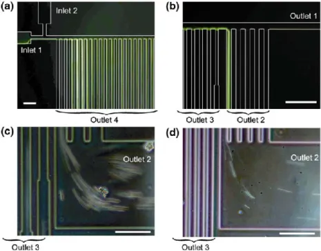
The techniques using microfluidic are commonly used to sort targets: separate a population into different groups depending on a criteria (size/dielectric properties/sensibility to magnetism…) which can be identified and used for separation depending on the active technology used. Thus each manipulation technique is specialized and operating on specific targets and properties. For sorting purposes some of them have proven to be efficient tools with good sorting accuracy results at a fast speed for big populations [33-35]. An example from the work of Masumi Y.
at al.[35] is presented in Figure 2.4. In this case different sizes of channels are used to sort a
population of targets (liver cells) depending on their size.
Figure 2.4: Cell sorting microfluidic device (Extracted from reference 23)
These techniques are relevant for sorting a population of target. They do not ensure static control of single elements of a population for further operations. The system we develop focus on the manipulation of single isolated elements. Such device generate a strong interest for our project as this could be used in addition to our manipulation, to select the target to be manipulated later among a population.
The function of the multiple flow manipulator we develop is different from the microfluidic sorting devices but they are complementary. In an industrial system, or as a future work, a combination of the two technology would have great potential.
2.6. Surface acoustic wave
A recent innovation in contact-free micro manipulation is the use of surface acoustic waves (SAWs). Still in development, there are already several applications in the bio field for this technology such as whole blood plasma and cells separation in a portable analysis system [38] or
droplets manipulation [37]. It rely on the use of the efforts generated by the propagation of SAWs
inside a fluid; the acoustic radiation force and the acoustic streaming drag force. The use of such technique is specific and dedicated to certain types of liquids containing different particles to be separated. The following figure 2.5 graphically represent the surface acoustic wave manipulation technique. The target can be floating on a liquid, immersed or contained inside a different phase of a non-miscible liquid. Sonic waves are generated inside the liquid and the target is stabilized in specific locations depending on the accumulation or annihilation of the sonic waves. The left part of figure 2.5 presents a focused wave configuration, used with ultrasonic wave for manipulation in the work of B. Zhu et al. in reference [28].
Figure 2.5: Surface acoustic wave graphical representation and focused wave technique This manipulation technique is relying on the propagation of a wave inside the fluid meanwhile our solution rely on the streaming of a flow; certain similarities can found but the
applications and scale are different. This technique is extremely efficient for particles separations but still unfit for single targets selection and manipulation [36].
On a smaller scale, for nanoparticles, similar strategies are done using the dielectrophoretic force in a stranding Wave Array Trap system [39].
2.7. Summary
As mentioned in the introduction, micro manipulation devices and technologies are specialized; the size (range) of the targets that can be manipulated, their properties, the environment and the tolerance to external stimulations are important factors to define when choosing a manipulator or a manipulation technology. The complexity and price range goes from extremely complex and expensive technologies for advance manipulation tasks of extremely small targets requiring strong knowledge of the manipulator for the advanced laser trapping technologies, to more affordable but highly specialized technologies that can be potentially harmful for the target for the electric field and magnetic field solutions.
The following table and figure 2.6 regroups the main information used to assess the potential use of the previously described technologies in our case. The key factors being the operating scale for target manipulation, as well as the limitation induced by the physical principle used on the target (size, properties, and resistance), the working environment and the potential for manipulation.
Technology Scale Physical principle Limitations
Optical tweezers 10nm-10µm Radiation force
Heat and radiations induced
Condition the target’s optical properties Electrostatic 50µm-1mm Dielectrophoretic force Conductive material preferred Magnetic No limitation Magnetic field Ferromagnetic target
required
Microfluidic 10µm-1mm Pressure force / Hydrodynamic No static control Fitted for multiple targets
Surface Acoustic
Waves (SAW) 0.4mm-1mm Acoustic drag force Acoustic radiation
Ergonomics
New method (still under development) Mechanical ○ Tweezer ○ Pipette ○ Gripper 1µm-1mm o Physical boundary o Vacuum force o Capillary force Direct contact Effort concentration Sensing tools Environment (gripper)
TABLE A – Micromanipulation technologies summary table
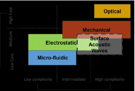
The following figure 2.7 proposes a schematic representation of the cost and complexity of a project, depending on the physical phenomenon used for the manipulation. A high complexity manipulator requires a complex setup and a trained manipulator while a low complexity manipulator is more flexible and can be used by a non-specialist. The graph highlight the main advantage of micro-fluidic solution; they can be adapted for an affordable cost.
The following table classify the different techniques depending on their control on the target (static control or dynamic positioning) and whether they offer a control on the target in 2 dimensions (channels, plates…) or in 3 dimensions (ambient fluid, 3D positioning).
Static positioning control Dynamic positioning control 2 Dimensional operation Electrostatic Electrostatic Micro-fluidic 3 Dimensional operation Mechanical Optical Magnetic
The following figure 2.8 represents the operability (complexity of the manipulation) of the different technologies depending on the size of the target as well as the concerns of our project.
Figure 2.8: Operability of the different technologies depending on the size of the target After studying the performances of several technologies and system, it appears that there is a lack of micromanipulators in the range 100µm-1mm that preserves the target from hard contact and harmful exposure to electro/magnetic fields and radiations. The relevance of the manipulation objectives and purpose of our solution in thus proven. Ensuring in addition an affordable cost and low experience requirement for the manipulator without strong restrictions on the target’s physical properties would then lead us to a remarkable tool for bio engineer and bio medical practices.
Chapter 3
Principle of manipulation by 3 micro-flows
3.1. Range, objectives and technical concerns of the solution
proposed
For the conception of a manipulator it is important to clearly identify and define the working environment and the purpose of the manipulation. In this project we focus on the manipulation of bio-targets in a micro scale. The targets size range from a millimeter to a hundred micrometers. This covers a wide range of targets such as small eggs, paramecium (unicellular organism), human skin cells… [51, 52] These are commonly used to study biology processes. Several
organisms are found in liquid environment since it make their development, motion and interaction with other organisms easier. The manipulator have to be operated in a liquid environment to avoid unnecessary harm on the targets due to an extraction from its natural environment.
The main purpose of the solution we propose is to protect the target from the potential damages caused by the manipulation. These organisms are highly sensible to any external stimulation; a concentrated physical effort will deform the shape of the target and affect its development, an exposition to radiations will alter or destroy its components and functions, potentially damaging it irreversibly. Each type of organisms presents its own weaknesses
depending on their reaction to the stimulation of different physical phenomena (heat, pressure, light exposure…). One of the objectives of the manipulation technique developed is to avoid any irreversible harm to the targets. The solution proposed rely on a physical contact but aims at avoiding harmful efforts concentration.
Another concern in the project being the cost, complexity and the congestion of the solution we propose. The biomedical equipment are usually expensive, thus requiring huge funding and the other manipulation solutions mentioned in section 2 often rely on complex technologies and require specific environments to be operated (clean room / huge available volume / special isolation / lighting…. ). One of the asset of the solution we offer is its convenience and low cost, making affordable for small laboratories and companies.
In order to conduct manipulation tasks, an effort has to be applied on the target. The choice of a manipulation method basically consists on determining the physical way used to apply the effort; dielectrophoretic force for the optical solution, contact pressure for mechanical solutions, electromagnetic forces… All of which have pros and cons (presented in section 2). In this project we chose to use a mechanical solution: a pressure applied on the surface of the target. The reason behind this choice is that the target will naturally be exposed to this type of efforts in its natural environment (e.g. a cell circulating through veins or an egg enduring different water pressure because of the current…) so it is logically possible to manipulate the target using such forces without it having any major impact on its structure and development.
The researches using such mechanism are usually relying on mechanical tweezers: a physical boundary being applied on two sides of the target making it unable to escape this location, followed by manipulation operations using the tweezers motion. This solution has proven its relevance but also its limits; to efficiently conduct these manipulation, a 3D actuation and control is necessary but complex for automation due to the lack of efficient force sensors and the problem of the 3D-percetion using optical assistance for the operator. In conclusion the manipulation is complex, the tools are fragile and a skilled operator is required to conduct proper manipulation tasks without damaging the target. One of the reasons behind the complexity of this manipulation technique is the nature of the force applied: a hard direct contact (with or without force feedback) concentrated on specific locations of the surface of the target leading to a forced boundary
limitation. To avoid facing these effort concentration concerns our solution rely on a spread application of the effort: a pressure applied by a controlled micro-flow.
Researches about the manipulation using micro flows have been carried before but they generally concerns a dynamic control of the target (e.g. cell sorting) while our research will focus on 2 aspects of the manipulation: a target extraction phase then a static control of the target. A static control of the target is essential for further tasks following the manipulation (observation / alteration / measurement / selection…). Several practical application require a static control of the target.
3.2. Holding configuration chosen and micro-flow manipulation
principle
Figure 3.1: Schematic Catching process.
Before complex manipulation tasks, the target has to be guided inside a zone called “control chamber” where the operator can apply his holding strategy to the target.
First the manipulator have to be positioned in a specific location around the target; this is the transition between state 1 and 2 in figure 3.1. Actuation of the manipulator is required for this step, the positioning can be done manually by the operator or automated. Then the target is inside the control chamber before the holding phase start; this is the
transition between state 2 and 3 in figure 3.1. This step is done using a pump presented in section 6 in the current system.
Following that, the target has to be caught and held in its stably designed location; this is the transition between state 3 and state 4 in figure 3.1, using a holding strategy. After that, advanced manipulation tasks or operations on the target can be carried by the operator. The holding configuration chosen consists of 3 flow pushing the target against a plane surface called “wall” as shown in figure 3.2. Using these 3 flows we can spread the effort required to maintain the target in that location on its surface, thus avoiding any effort concentration. In the future the “wall” structure shall be functionalized to carry on the desired operation. For example micro-sensors array shall be embedded on the wall to monitor the condition of the bio target. Currently, in the chosen configuration all 3 flows are equidistant and the stable positon of the target is located against the wall, in the center of the nozzles. The flows coming out of the 3 nozzles are connected to a system controlling their pressure/flow rate to stably hold the target while limiting the pressure applied by the flow.
Figure 3.2: Holding Principle of the target by 3 flows.
The idea behind the use of 3 flows is to create a stable equilibrium location for the target; once in the center if the target’s position is affected by a perturbation it will be pushed back to the stable location by the flows it approaches. These considerations are discussed in the theoretical model dedicated section (section 5). The purpose of the wall is to be used as a reference surface for manipulation but also to host sensors and tools to conduct measurements
and operations on the targets: this research focus on the manipulation part but there are several potential application that could be implemented.
Figure 3.3 presents the symmetrical configuration of the 3 nozzles/flows chosen. The distance between the nozzles and the center is to be adapted to the size of the target. We currently have a fixed diameter for every manipulation task but the development of an adaptable diameter is being considered. Being able to remotely modify this distance while manipulating the target would improve the potential of the manipulation and orientation control of the target since the size of targets of the same nature vary depending on individuals; it would be possible to increase the stability and ease the manipulation. The size of the nozzles is currently defined by the manufacturing processes available (size of the drill); we tested 2 types of nozzles size – ø0.2mm and ø0.33mm.
Figure 3.3: Symmetrical Configuration of the three flows.
Note that in this configuration there is still a direct “soft” contact to the target coming from the wall. The surface of the wall currently in use is rather rough to ensure the “roll without slide hypothesis” (mentioned in section 5), meaning that the target, once under the pressure of the 3 flows, should not slide on the wall (rotation around itself). The efforts generated by the flows affecting the target can be minimized to limit the alterations of the cell’s shape (deformations) through a flow control and minimized pressure.
The 3 flow configuration can be described using 3 key parameter, represented in the figure 3.4:
The nozzle output diameter (size of the nozzles), which influence the flow rate and the area affected by the pressure of the flow.
The nozzle spacing diameter, which influence the distance between the nozzles symmetrically positioned on this circle, the position of the pressure application on the target and define the stable area location of the target.
The holding gap is the distance between the wall and the nozzle output, it influence the behavior of the flow (laminar/turbulent/vortices) and the pressure loss of the flow after entering the ambient fluid.
Figure 3.4: Representation of the important parameters used to describe the configuration.
3.3. Previous works and discussion
Previous studies were done using this configuration [50] and the conclusions concerning
dimensions and distances were considered during the design of the system presented in section 5. For example, it has been observed that with a 1mm target, having the nozzles at a distance of 1.5 to 4mm from the target brings better results for stability. Different tests were conducted in order to define a suitable configuration for the manipulation. The behavior of a flow can be
described using a numerical value called the Reynolds number. More information and the calculation of the estimated Reynold number in our case are given the model section (5.2.1).
Using the Reynolds number, one can estimate the whether the flow will act as a laminar flow or a turbulent flow. For stability and predictability in the manipulation, a laminar flow is preferable to a turbulent one. The determination of the Reynolds number and determination of a flow’s behavior can be done through its observation, but in a transparent liquid an assistance for flow visualization is required. A tool for flow visualization was developed and is presented in the section 4. Using this tool, observation of the behavior of the flow and of the flow/target interaction were conducted. The figure 3.5 display the transition of a laminar flow into a turbulent using the chemical tool developed. These conclusions were considered as well during the design of the system and the flow rate requirements determination.
Chapter 4
Chemical visualization for micro flows
4.1. The need for data collection and tools limitations
The chapter 3 presented the chosen configuration and highlighted the different important parameters for the design of the system. A lack of information on the flow’s behavior and properties would lead to a blind luck/try-and-error calibration and design, hence data collection about the flow’s behavior is a key factor in this research. It is also crucial to conduct reproducible flow experiments to justify the hypothesis made during the design of the model.
Having a transparent flow makes it inconvenient for observation. Using optical tools, one can conduct observations of the flow without altering it, but this equipment is expensive and its use is complex for non-experimented researchers (optical field technologies, calibration required). Moreover the flow-target interaction in itself is complex and undocumented; having concrete direct observation of this phenomena would support most researches involving interactions between a flow streaming and an object or surface and ease the pre-analysis and setup of the experiment. An affordable and convenient tool for direct observations of a flow would be greatly appreciated, as shown by the interest the community had in the paper presented in the ICMA international conference in October 2017[53]. This paper was the first publication of the results of
4.2. The innovative chemical visualization principle
Different chemical visualization techniques already exists but they are mainly used in a context where a flow stream is being evacuated (e.g. stream inside a pipe). A common technique consists on mixing or replacing the flow streaming with ink in order to differentiate it from the ambient fluid, enabling the user to conduct direct visual observation of the flow. The difference with a closed environment is that the ink is not being evacuated, hence after a certain time the environment becomes saturated with ink and the flow cannot be differentiated anymore. The maximum time during which observations can be conducted is called saturation time. The ink technique has been used by some co-researchers in micro-fluidic systems and the results were used to support the design and optimization of their system. In order to enhance the saturation time and thus enable longer observation span a technical solution has been designed. Not being a professional chemist, the solution proposed here rely on simple chemical principles and uses tools that can be easily acquired.
The main goal was to design a tool to differentiate the flow from its environment for a limited amount of time, from which we seek information, and that once the flow becomes part of its environment and mixes with it and cannot be differentiated anymore (the flow’s cohesion stops existing). Hence if the nature of the flow itself just after entering was slightly different from the ambient fluid, if the flow could be differentiated using this parameter before it mixes and then becomes homogeneous, the user would be able to identify and observe it during its first instant after entering the environment, until the flow mixes with it and “vanishes” (cannot be distinguished anymore). This is being done using the pH parameter. The pH of a liquid refers to its concentration in hydronium ions through the water autoprotolysis and is used to measure the acidity level of a solution (0-14 acid/basic scale). There are commonly available tools to physically observe and distinguish a liquid depending on its pH level: the colored indicators, some of which being transparent or colored depending on the acid or basic characteristic of the solution were highly interesting for us. The solution proposed is to use an acid/basic differentiation of the incoming flow and the ambient liquid with a colored indicator to observe it.
The ambient liquid used in our experiment is water, which have a neutral pH. To successfully conduct the observations, the ambient fluid should be transparent, while the incoming flow should be colored. There are several colored indicator available on the market but 2 specific ones stood out due to their color reaction.
The phenolphthalein is orange when exposed to strong acid environment (not happening in our case), colorless when exposed to acid and neutral environment (pH 0 to pH 8.2), pink when exposed to a basic environment (pH 8.2 to pH 12) and transparent when expose to strong basic environment (not happening in our case).
The bromothymol blue is pink when exposed to strong acid environment (not happening in our case), yellow when exposed to and acid environment (pH 0 to pH6), gradually turn from yellow to blue in green shades when exposed to neutral environment (pH 6 to 7.6) and is blue when exposed to basic environment (pH > 7.6).
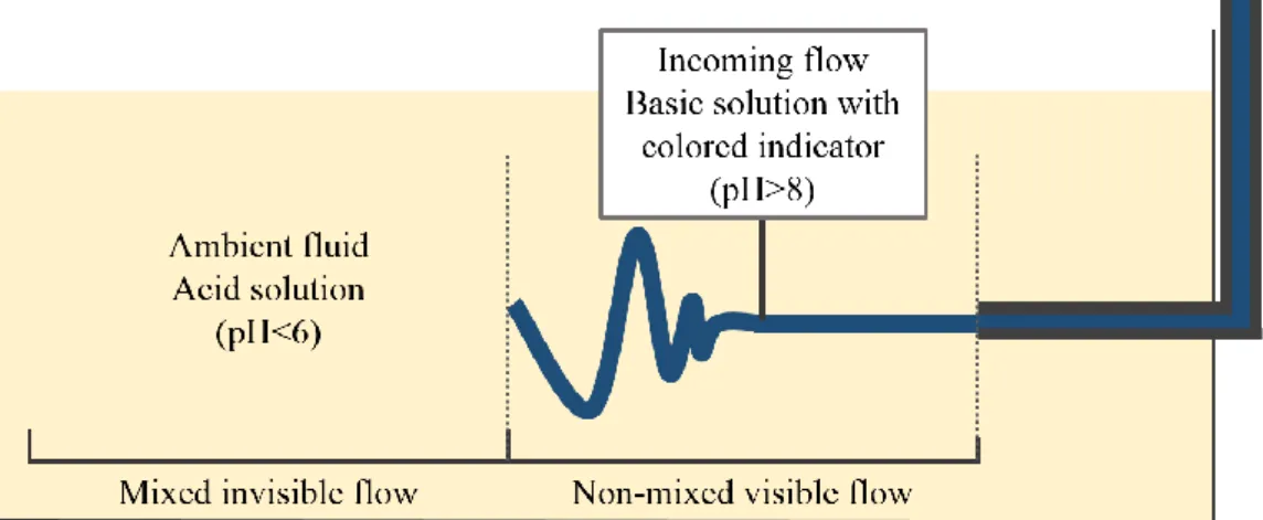
Both the phenolphthalein and the bromothymol blue present strong colors when exposed to basic and environment and colorless of light color when exposed to acid environment. Using these properties, the principle of the chemical flow visualization is to mix the incoming flow with a basic solution to increase its pH (basic) and one of the colored indicator, while the ambient liquid is mixed with an acid solution to lower its pH (acid). Hence, the flow coming out will have a strong color depending on the color indicator used (pink for the phenolphthalein, blue for the bromothymol blue) and as it enters the ambient fluid and starts mixing, its pH will decrease and the color will change to match the transparent or light color of the ambient fluid. The length of the stream that can be observed depends on the pH and dynamic properties of the flow (laminar/turbulent behavior, speed, size, obstacles on the path). The figure 4.1 describe the configuration used for the chemical visualization.
Figure 4.1: Flow visualization configuration.
4.3. Tests and performances of the chemical visualization tool
Through the chemical visualization strategy presented we could efficiently conducted observations of the flow for a long time without interruption: over 20 min continuously, compared to tens of seconds at most using the ink injection techniques. The cost of the different chemical elements used is low and they are easily available. Although the first tests using commercially, commonly available products were successful, we chose to buy chemically pure and controlled elements for our observations to avoid undesired chemical reaction (oxidation of the bromothymol blue…). This tool can be used in any kind of micro-fluidic system that is not sensible to acid/basic environment. Once the solution mixes are ready there is no further calibration required, making it an extremely convenient and polyvalent tool.
Tests were conducted in order to determine which chemicals and colored indicator within the ones available were best to use. The decision was made to use an acetic acid solution and a sodium hypochlorite solution. The phenolphthalein was chosen over bromothymol blue as a colored indicator for its longer coloration time and chemical stability in this use. Liquid version of the colored indicator is preferred to powder version to simplify the mix; constant mixing creating potential turbulences inside the flow and the big pieces of undissolved powder could obstruct the instruments. The incoming flow was a water/base mix with the colored indicator; the concentration of basic element has to be sufficient to distinguish it from the acid. A high
time due to the saturation of the ambient fluid. The ambient liquid was a water/acid mix with a relevantly high concentration of the acid to extend the observation time (slow the pH saturation from the incoming flow). The optimal concentrations depending on the type of observations being conducted by the operator with concerns of differentiation span of the incoming flow, overall desired observation time and acid/basic liquid exposure of the system.
The mix shall be adapted to the observation one wants to conduct. In a closed space, minimizing the phenolphthalein and base concentration to the minimum required can greatly improve the saturation time. In open liquid, the concentration in acid doesn’t have to be as strong as in closed space; the density of the incoming flow and ambient fluid can remain similar. In an 80x80x80mm cubic observation tank, acetic acid concentrations below 0.25mol/L are more than sufficient for a 20 min observation time. The tests were carried with a concentration between 0.1 and 0.25mol/L of acetic acid in the observation tank. The base and phenolphthalein mix was prepared using 300mL of water, 50mL of a 10g/L diluted phenolphthalein solution and 5 to 15g of sodium hypochlorite solution.
Note that the chemical visualization tool and the detail of the following test results using it purely serves the purpose of the preliminary study of the flow and the flow-target interaction but the harm caused to the target makes this tool unusable in a situation where the target have to be preserved. This tool is not meant to be used as a visual sensor in the final version of the system. As for a fish egg kind of target used in the following tests conducted, it can only be used with this tool for up 5minutes at most before its structure’s alteration makes it irrelevant for further test. Aside from the fish eggs, different spherical targets were used, mainly glass balls whose diameter range from 3mm to 600μm.
4.4. Experimental results of the visualization
4.4.1. Visualization limits and saturation
The equipment cost for conducting the chemical visualization is more than 10 times cheaper than a simulation software. The visual results using the chemical visualization tool are highly reliable to confirm hypothesis when the tests conducted are accurately reproducing the
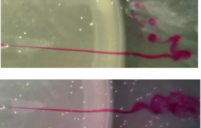
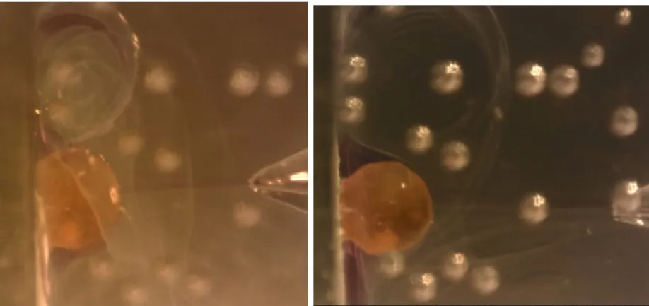
actual condition of the system. Still, the conclusions should account the fact that the flow’s properties are not exactly identical (density of the liquid, cohesion of the stream, damages to the target…) and the operator has to limit as much as possible the impact of these differences during the experiment; changing the target regularly, balancing the concentrations to adapt the density… The figure 4.2 display an example of a target before and after being in contact with the chemicals for visualization. The surface slowly turns white and thickens. The figure 4.3 is an example of the progressive saturation process of the ambient fluid; a white precipitate slowly appear on top of the water tank.
Figure 4.2: Target glued to a wall for observations: New (left) and after 5 min of contact with the flow for visualization (right).
4.4.2. Data collection
In order to design the system different information are required. The 3 flow manipulation relies on the interaction between the flow coming out of 3 nozzles and the target being manipulated. The following figure 4.4 displays the experimental setup used for data collection with the chemical visualization. The flow is generated and controlled trough a height difference between the water tank (supply, basic) and the observation tank (acid). The flows comes out of a custom glass micropipette whose position is controlled using 2 to 3 manual linear actuators.
The information related to an ideal position of the nozzles are: the size of the nozzle (their diameter), the distance between them (spacing) and the gap between the tip of the nozzle and the wall behind the target. The optimization of these parameters shall ensure that the flows remain laminar during their interaction with the target, that the interaction with the target can be suitably apprehended and simulated (contact surface variation) and that a perturbation inside the flow does not affect the stability of the target too much (propagation of the perturbations).
Moreover, in order to setup a control strategy, information relative to the flow-target interaction are required. One of the most important and desirable information in theoretical fluid mechanic is the streamlines information. This parameter indicate the direction taken by the flow and can be used to determine its interaction with its environment. The direction and value of the efforts, the speed of the flow can be determined and the appearance of local phenomenon such as vortices can be observed. In our case the information researched are the direction of the flow and the nature of its interaction with the target. Notably, the contact surface variation of flow-target interaction depending on their relative position is a key parameter used in the model. In order to stably manipulate the target, a range of values for an ideal flowrate range to be used is also researched.
4.4.3. Flow stability and streamlines visualization
One of the first simple tests that was conducted concerned observations of the behavior of the flow. Depending on different parameters, a flow can act in different; a linear, coherent flow sliding through the ambient environment has a behavior called “laminar” and a chaotic, oscillating non-linear flow is called “turbulent”. A theoretical value calculated using different parameters such as the speed the flow, viscosity of the fluid and a scale factor called the Reynold number can be used to estimate the behavior of the flow. But this number has been established empirically using experimental values to define the value separating the two potential behavior, and although it can give some indication about the theoretical behavior of the flow, it should be confirmed using experiment observations. The tool developed enable the user to determine the behavior of the flow and the transition between the two states. The figure 4.5 is an example of such observation; the pictures present a flow entering the ambient fluid at a flowrate close to the ones
![Figure 2.3: Dielectrophoretic force applied to micro manipulation: generation of different patterns (top) and positioning results and resulting field for the patterns A and B (Bottom) [49]](https://thumb-ap.123doks.com/thumbv2/123deta/7729828.1711535/23.892.115.784.272.809/dielectrophoretic-manipulation-generation-different-patterns-positioning-resulting-patterns.webp)