52 752 平成18年11月 8 日 第47回真空に関する連合講演会で発表 1 埼玉大学大学院理工学研究科(〒3388570 埼玉県さいたま市 桜区下大久保255) 2 高エネルギー加速器研究機構(〒3050801 茨城県つくば市大
穂 11) Fig. 1 Gap current, and applied voltage waveforms.
52 752 ―( )― J. Vac. Soc. Jpn.(真空)
速
報
真空ギャップのスパークコンディショニング
処理過程で生じるパルス状電流の観測
川田
将司
1・山納
康
1・齊藤
芳男
2・小林
信一
1Observation of Pulse Current Occurring during Spark Conditioning Process of a Vacuum Gap
Masashi KAWADA1, Yasushi YAMANO1, Yoshio SAITO2and Shinichi KOBAYASHI1
1Graduate School of Science and Engineering, Saitama University, Saitama-shi, Saitama 3388570 2High Energy Accelerator Research Organization (KEK), Tsukuba-shi, Ibaraki 3050801
(Received May 28, 2007, Accepted October 13, 2007)
It is known that the hold-oŠ voltages of vacuum gaps can be improved by the spark conditioning with repetitive electrical break-downs. At the initial stage of spark conditioning process, small pulse currents (not breakdowns) were observed, and in turn hold-oŠ voltages were improved. To clarify the generating mechanism of the pulse current and the reason of the improvement in hold-oŠ vol-tages, repetitive pulse current was generated, and chemical compositions of the electrodes were analyzed before and after experi-ments. The analysis of chemical compositions was carried out by a X-ray photoelectron spectroscopy (XPS). The XPS analysis rev-ealed that only the anode surface was cleaned by repetitive pulse current ‰owing. This result suggests that cleaning the anode surface by repetitive pulse current ‰owing would be one of causes of the improvement in hold-oŠ voltages of a vacuum gap at the initial stage of conditioning process. . は じ め に 真空ギャップの絶縁耐力向上を図る上で問題となるのが電 極表面の付着汚染物や吸着ガス,微小突起などであるが,こ れまでの研究報告により,絶縁破壊を繰り返すスパークコン ディショニングにより電極表面が清浄化され絶縁耐力が向上 することが確認されている1).著者らは,このスパークコン ディショニング処理過程の初期段階で,高電圧印加により, パルス状の電流が発生することを観測し,さらに,この現象 の発生によってもスパークコンディショニング同様,絶縁耐 力 の 向 上 を 確 認 し た . こ の パ ル ス 状 の 電 流 は , microdischarge と呼ばれてきた現象に類似しているが24), 本研究では真空の条件が異なるので,ここではパルス状電流 と呼ぶことにした. 本論文では,無酸素銅電極を用いて繰り返しパルス状電流 発生試験を行い,パルス状電流に絶縁耐力向上作用があるの か調査した.また,これまでに報告されている研究において は電極表面の化学的状態が明らかではなかったが,本研究で は,同一真空環境下での実験前後における表面状態を明らか にし,パルス状電流発生による電極表面状態への影響を調べ た.なお,本研究での電極の表面分析は,X 線光電子分光 法(XPS: X-ray Photoelectron Spectroscopy)を用いた.
. パルス状電流発生による放電現象について Fig. 1 は繰り返し絶縁破壊試験中にディジタルオシロス コープで観測された電圧・電流波形の一例である.Fig. 1 (a)は絶縁破壊が生じた際のギャップ間電圧電流波形であ る.絶縁破壊が発生すると,電圧が急激に降下し,電流が飛 躍的に増大する.その時電極ギャップ間では激しい発光が見 られる.一方,Fig. 1(b)の電圧・電流波形のように,ギャ ップ間電圧はほとんど変化なく,パルス状電流が発生する場
53 753 Fig. 2 Example of the improvement in hold-oŠ voltages by
the pulse currents and breakdowns.
Fig. 3 In-situ experimental apparatus. Fig. 4 Electrode geometry.
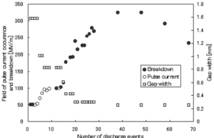
53 753 ―( )― Vol. 50, No. 12, 2007 合がある.この場合,ギャップ間の発光は弱く,目視できな い場合がほとんどである. Fig. 2 にスパークコンディショニングの初期段階におけ るパルス状電流発生電界(ギャップ間電圧/ギャップ長)と 絶縁破壊電界(絶縁破壊電圧/ギャップ長)を示す.中抜丸 はパルス状電流発生電界であるが,発生回数ごとに電界強度 が増していることがわかる. . 実験装置・方法 本研究では,各種表面処理,XPS 表面分析および絶縁破 壊試験等を10-7~10-8Pa の同一真空系内で行うことができ る in-situ 実 験 装置 を 使 用 し た. Fig. 3 に そ の 概 略 図を 示 す.この装置により,大気の影響を受けずに,常に超高真空 内で一連の実験及び測定を行うことが可能となっている.こ れらの実験装置は,シールドルーム内に設置されているた め,通常のスパークコンディショニング処理中のような絶縁 破壊時に生じるノイズによる測定系への影響は除去される仕 組みとなっている. Fig. 4 に本研究で用いた試料電極の形状を示す.試料電 極の材質は Class1 の無酸素銅であり,Fig. 4 に示すように, in-situ 実験装置用の電極ホルダーに取り付けられるよう加 工してある.本研究では,この電極の曲面部分を対向させて ギャップを構成し,最大波高値100 kV,波頭長64 ms,波尾 長700 ms のインパルス電圧を印加することで繰り返しパル ス状電流発生試験を行った. 本実験では繰り返しパルス状電流発生試験中,ギャップ長 を変化させるため,絶縁耐力の評価は電界(パルス状電流発 生電圧/その時のギャップ長)で行った. . 結果と考察 Fig. 5 に繰り返しパルス状電流発生試験の結果を示す. 繰り返し発生試験を28回で中断しているのは,ギャップ長 1.3 mm で80 kV のインパルス電圧を印加してもパルス状電 流が発生しなかったからである.ここで,さらにパルス状電 流を観測するためギャップ間の電界を高める目的でギャップ 長を縮め,電圧を印加すると,経験的に絶縁破壊が発生する 可能性が高いためである. Fig. 5 を見ると,絶縁破壊することなくパルス状電流のみ で電界が高まっていることがわかる.繰り返しパルス状電流 発生試験を行っている際に,発生したパルス状電流の振幅を 測定したところ Fig. 6 のような結果となった.全体的にパ ルス状電流値を見ると数~数十 mA 程度であり,数 A 単位 で流れる絶縁破壊時の放電電流に比べると微小な電流である といえる.発生回数に対する電流値の関係を見ると,最初の 2 回だけはやや大きな電流が流れ,それ以降の値は大きくば らつく結果となり,発生回数に対する電流値の依存性は見ら れなかった.これは発生回数ごとに,電極表面のパルス状電 流発生点が変わっていることが原因と考えられる. Fig. 7 はパルス状電流発生試験前後の XPS 表面分析結果 を示す. この図からわかるように,試験前,すなわち in-situ 装置 への導入直後の電極表面は,炭化水素に起因する C のピー クや酸化物に起因する O のピークが存在し,電極材料であ る Cu のピークが不明瞭であるため汚染層に覆われていると いえる.しかし,パルス状電流発生試験を行った後のスペク トルを見ると,陰極については試験前後ではほとんどスペク トルに変化はないが,陽極では試験後,C のピークは消滅,
54 754
Fig. 5 Improvement characteristics of ˆeld with the accumu-lation of pulse current occurrence.
Fig. 6 Peak value of pulse current as a function of number of pulse current occurrence.
Fig. 7 XPS spectra before and after repetitive pulse current occurrence test. 54 754 ―( )― J. Vac. Soc. Jpn.(真空) O のピークは小さくなり,Cu のピークは試験前に比べてか なり明瞭となった.これはギャップ間でパルス状電流を繰り 返し発生させたことで,陽極の汚染物が除去され,代わりに 陰極へ移動または空間へ拡散したためと考えられる. . ま と め 真空ギャップのスパークコンディショニング過程の初期段 階で,絶縁破壊を伴わないパルス状電流を発生させ,その電 流値を測定した結果,その電流の大きさは数~数十 mA 程 度であり,数 A 流れる絶縁破壊時の放電電流に比べると微 小であることがわかった.また,パルス状電流値は,最初の 2 回は約100 mA 程度の電流が流れ,その後は電流値が大き く変動した.このことから,電極表面上でその発生点が変わ っていることが考えられた. また,パルス状電流を繰り返し発生させることで,陽極表 面が清浄化された事を確認した.しかし,さらにパルス状電 流を発生させた場合,陰極の表面状態にも影響を及ぼす可能 性が残っていることも考えられ,再現性を取る意味も含めて 同様の実験を続ける必要がある. 〔文 献〕
1) S. Kobayashi: IEEE Trans Dielectrics and Electrical Insulation, 4 (1997) pp. 841847.
2) 鶴田浩一電気学会論文誌 A,基礎・材料・共通部門誌,Vol. 110A, No. 6 (1990) pp. 356362.
3) R. V. Latham: High Voltage Vacuum Insulation, (Academic Press, 1995) pp.2326.
4) O. Yamamoto, T. Hara, M. Shimada and M. Hayashi: IEEE Trans on Electrical Insulation,Vol. 28, No. 4 (1993) pp. 574579.