Measurement of absolute
frequency of continuous-wave
terahertz radiation in real
time using a free-running,
dual-wavelength mode-locked,
erbium-doped fibre laser
Guoqing Hu
1, Tatsuya Mizuguchi
2, Xin Zhao
1, Takeo Minamikawa
2,3, Takahiko Mizuno
2,
Yuli Yang
1, Cui Li
1, Ming Bai
1, Zheng Zheng
1,4& Takeshi Yasui
2,3A single, free-running, dual-wavelength mode-locked, erbium-doped fibre laser was exploited to measure the absolute frequency of continuous-wave terahertz (CW-THz) radiation in real time using dual THz combs of photo-carriers (dual PC-THz combs). Two independent mode-locked laser beams with different wavelengths and different repetition frequencies were generated from this laser and were used to generate dual PC-THz combs having different frequency spacings in photoconductive antennae. Based on the dual PC-THz combs, the absolute frequency of CW-THz radiation was determined with a relative precision of 1.2 × 10⁻⁹ and a relative accuracy of 1.4 × 10⁻⁹ at a sampling rate of 100 Hz. Real-time determination of the absolute frequency of CW-THz radiation varying over a few tens of GHz was also demonstrated. Use of a single dual-wavelength mode-locked fibre laser, in place of dual mode-locked lasers, greatly reduced the size, complexity, and cost of the measurement system while maintaining the real-time capability and high measurement precision.
Terahertz (THz) radiation covers an extremely wide electromagnetic band that potentially could be leveraged for high-speed communications, and investigation of THz radiation has attracted increasing interest1,2. With
the development of various continuous-wave THz (CW-THz) radiation sources, such as THz quantum cascade lasers3 and uni-traveling-carrier photodiodes4, THz wireless communication is highly promising, even though
frequency allocation in the THz band (0.275–3 THz) has not yet been established. For the purpose of evaluating sources and considering suitable frequency allocation, it is essential to precisely determine the absolute frequency of CW-THz radiation. Although the electrical heterodyne method5 and the optical interferometric method have
been used for measuring the absolute frequency of CW-THz radiation, both of these methods need cryogenic cooling to reduce thermal noise, hindering the wide adoption of these methods in various practical applications. Therefore, there is a strong demand for absolute frequency measurement in the THz region without the need for cryogenic cooling.
One promising method of achieving this is the scheme based on photoconductive mixing of CW-THz radi-ation with a THz frequency comb of a photo-carrier (PC-THz comb) in a photoconductive antenna (PCA)6–11.
In this scheme, the absolute frequency fTHz of CW-THz radiation can be determined from a PC-THz comb
1School of Electronic and Information Engineering, Beihang University, Beijing, 100191, China. 2Graduate School
of Science and Technology, Tokushima University, 2-1 Minami-Josanjima, Tokushima 770-8506, Japan. 3JST,
ERATO, MINOSHIMA Intelligent Optical Synthesizer Project, 2-1 Minami-Josanjima, Tokushima 770-8506, Japan.
4Collaborative Innovation Centre of Geospatial Technology, 129 Luoyu Road, Wuhan 430079, China. Correspondence
and requests for materials should be addressed to Z.Z. (email: zhengzheng@buaa.edu.cn) or T.Y. (email: yasui. takeshi@tokushima-u.ac.jp)
received: 22 August 2016 accepted: 03 January 2017 Published: 10 February 2017
mode m nearest in frequency to fTHz, the frequency interval frep of the PC-THz comb, and the beat frequency
fbeat between the CW-THz radiation and the m-th comb mode. While frep and fbeat can be directly measured
in the radio-frequency (RF) region, m can be determined by two different frep values and their
corre-sponding fbeat values. In early research6–8, the determination of m was based on time-sequential, two-step
measurement of frep and fbeat with a single PC-THz comb induced by an frep-adjustable mode-locked laser.
Therefore, fTHz could not be determined in real time. Recently, dual PC-THz combs with different frep
have been used to achieve the real-time determination of fTHz based on simultaneous measurement of two
frep values and their corresponding fbeat values10. In that study, by using dual stabilized or free-running
mode-locked lasers with different frep for the generation of dual PC-THz combs, fTHz was determined
precisely at a measurement rate of 100 Hz. However, use of dual laser systems hinders the wider adop-tion of such techniques. More recently, the real-time determinaadop-tion of fTHz was achieved by using a single
mode-locked laser with an actively modulated or smoothly drifting frep11; however, the measurement rate
remained at 10 Hz due to the time-sequential, fast-two-step measurement of frep and its corresponding
fbeat with a single PC-THz comb. If dual PC-THz combs with different frep could be generated by a single
free-running mode-locked laser, the real-time capability, precision, and practicability of THz frequency measurement would be enhanced.
Recently, the use of ‘multiplexed’ mode-locked erbium-doped fibre (Er:fibre) lasers as dual-comb lasers has been demonstrated by multiplexing in the dimensions of centre wavelength, propagation direction, polarization state, or mode-locking mechanism12–17. Among these schemes, use of a dual-wavelength
(dual-λ ) mode-locked Er:fibre laser is a promising way to generate a dual PC-THz comb because it emits two independent mode-locked pulsed light beams with different wavelengths, λ1 and λ2, from a single
cav-ity, and their frep values are slightly detuned from each other due to dispersion in the fibre laser cavity18. The
pulsed light beams with wavelengths λ1 and λ2 can be easily separated by optical filters, and the difference
in frep between them can be adjusted by dispersion management in the fibre cavity. Also, the common-mode
noise between the λ1 and λ2 pulsed beams is effectively cancelled by co-propagation of them in the same
cavity19. Such characteristics in dual-λ mode-locked Er:fibre lasers have been successfully used in
asynchro-nous optical sampling (ASOPS) pump-probe measurement18, optical ranging20, and optical spectroscopy19.
However, there have been no attempts to apply the technique to THz measurement. In this paper, we used a dual-λ mode-locked Er:fibre laser for rapid, high-precision measurement of fTHz based on dual PC-THz
combs.
Principle of Operation
THz-comb-referenced frequency measurement is based on heterodyne photoconductive mixing between CW-THz radiation and a PC-THz comb6,7. Two essential conditions must be satisfied: (1) a PCA must work
as a broadband heterodyne receiver with high sensitivity for THz radiation at room temperature, and (2) the generated PC-THz comb should cover the whole THz band. When CW-THz radiation (freq. = fTHz) is
photocon-ductively mixed with one mode of a single PC-THz comb (freq. interval = frep, comb mode nearest in frequency
to fTHz = m), fTHz is given by
= ±
fTHz m frep fbeat (1)
where fbeat is the beat frequency between CW-THz radiation and the m-th comb mode.
Next we consider the photoconductive mixing of CW-THz radiation with dual PC-THz combs having dif-ferent frequency spacings (PC-THz comb 1, freq. interval = frep1, comb mode nearest in frequency to fTHz = m;
PC-THz comb 2, freq. interval = frep2, comb mode nearest in frequency to fTHz = m). In this case, when frep2 > frep1,
fTHz is given by
= ± = ±
fTHz m frep1 fbeat1 m frep2 fbeat2 (2)
where fbeat1 is the beat frequency between the CW-THz radiation and the m-th comb mode in PC-THz comb1,
and fbeat2 is the beat frequency between the CW-THz radiation and the m-th mode in PC-THz comb2. From
Eq. (2), m can be calculated by
= ± ± −
m f f
fbeatrep22 frepbeat11 (3)
where the signs of fbeat1 and fbeat2 are determined by the relative positions of fTHz, mfrep1, and mfrep2.
Figure 1 shows the relative position of fTHz (see green line) to the nearest modes mfrep1 (see red lines) and
mfrep2 (see blue lines) in the dual PC-THz combs, where (a) fTHz < mfrep1 < mfrep2, (b) mfrep1 < fTHz < mfrep2,
and (c) mfrep1 < mfrep2 < fTHz. Since the frequency difference between frep1 and frep2 ( = frep2 − frep1 = ∆frep) is the
denominator of Eq. (3), a highly stable frequency difference is essential for accurately determining m. The relative positions of fTHz, mfrep1, and mfrep2 can be determined from the simultaneous measurements of frep1, frep2,
< < − > = < < + = = − < < − < = (4) f mf mf f f AND Sign df dt Sign df dt mf f mf f f const OR Sign df dt Sign df dt mf mf f f f AND Sign df dt Sign df dt 0 0 THz rep rep
beat beat beat beat
rep THz rep
beat beat beat beat
rep rep THz
beat beat beat beat
1 2 2 1 1 2 1 2 2 1 1 2 1 2 2 1 1 2
Therefore, m can be obtained by
Figure 1. Relative positions of fTHz, mfrep1, and mfrep2. (a) fTHz < mfrep1 < mfrep2, (b) mfrep1 < fTHz < mfrep2, and (c)
= − − < < = + − < < = − + − < < m f f f f f m f m f m f f f f m f f m f m f f f f m f m f f (5) beat beat
rep rep THz rep rep
beat beat
rep rep rep THz rep
beat beat
rep rep rep rep THz
2 1 2 1 1 2 2 1 2 1 1 2 2 1 2 1 1 2
Finally, fTHz can be determined by
= − = − < < + = − < < + = + < < f m f f m f f f m f m f m f f m f f m f f m f m f f m f f m f m f f (6) THz
rep beat rep beat THz rep rep
rep beat rep beat rep THz rep
rep beat rep beat rep rep THz
1 1 2 2 1 2
1 1 2 2 1 2
1 1 2 2 1 2
Results
Free-running, dual-λ mode-locked Er:fibre laser.
Figure 2(a) shows the configuration of the free-run-ning, dual-λ mode-locked Er:fibre laser oscillator. With birefringence-induced filtering and loss control effects12,13,19,in addition to the adjustment of the polarization state in the ring cavity, simultaneous mode-locking centred on the 1530-nm and 1560-nm regions can be realized. As shown in Fig. 2(b), the centre wavelengths of dual-λ pulses were 1531.4 nm and 1556.1 nm, with corresponding 3-dB bandwidths of 2.2 nm and 3.3 nm, respectively. Because of the anomalous intracavity dispersion, the dual-λ pulses had different repetition rates around 32.06 MHz (frep1 = 32,066,206 Hz, frep2 = 32,067,857 Hz) with a difference ∆frep ( = frep2 − frep1) of ~1.63 kHz, as shown in Fig. 2(c).
In order to meet the optical power and pulse duration requirements for PCAs, the λ1 and λ2 pulses from the
laser oscillator were separated by a coarse-wavelength-division-multiplexing bandpass filter (CWDM-BPF) [not shown in Fig. 2(a)]. Figure 3(a and b) show optical spectra and RF spectra of the λ1 and λ2 pulses after passing
through the CWDM bandpass filter. The dual-λ mode-locked fibre laser light was successfully separated into
Figure 2. (a) Configuration of free-running dual-λ mode-locked Er-doped fibre laser oscillator. LD, 980-nm pump
diode; WDM, 980/1550 nm wavelength-division multiplexer; SMF, single-mode fibre; EDF, erbium-doped fibre; ISO, polarization-independent optical isolator; SWNT-SA, single-wall carbon nanotube saturable absorber; PC, fibre-squeezer-based polarization controller; OC, 90/10 fibre output coupler; ILP, in-line polarizer; PMF, polarization maintaining fibre. (b) Optical spectrum and (c) RF spectrum of the output light from the laser oscillator.
each component in the optical region and the RF region. Then, the components were amplified and spectrally broadened by erbium-doped fibre amplifiers (EDFAs) and the following SMF, respectively. As shown in Fig. 3(c), the optical spectrum of the amplified λ1 pulsed light covered the whole C band, whereas that of the amplified λ2
pulsed light was located at the shorter wavelength side. The mean power and the pulse duration were 27 mW and 130 fs for the amplified λ1 pulsed light [see Fig. 3(d)] and 20 mW and 130 fs for the amplified λ2 pulsed light [see
Fig. 3(e)] when the SMF was used to compensate for the dispersion. These output characteristics were sufficient to generate a PC-THz comb in PCA.
Before performing real-time measurement of fTHz with dual PC-THz combs, we investigated the frequency
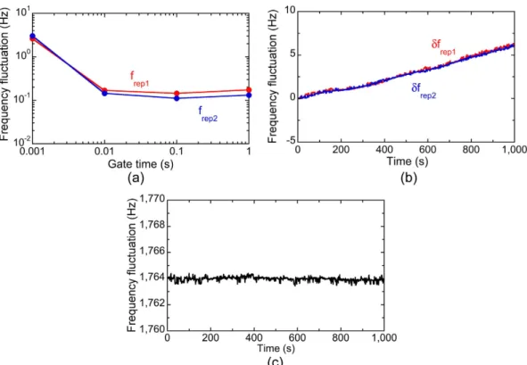
characteristics of this free-running laser. We first measured the temporal fluctuations of frep1 and frep2 with a
fre-quency counter (Agilent 53132 A). Figure 4(a) shows the fluctuations with respect to different gate times. Due to the free-running operation without active frequency control, the fluctuations of frep1 and frep2 did not decrease over
a gate time of 0.1 s. However, these fluctuations were comparable to those of other commercialized, free-running single-wavelength lasers10,11; this is clear evidence that the two mode-locked operations at λ
1 and λ2 do not
com-pete with each other and are completely independent of each other. Figure 4(b) shows the temporal fluctua-tions of frep1 and frep2, where their frequency deviations from the initial values are indicated by δfrep1 and δfrep2. A
slow drift was clearly confirmed for both, indicating changes in the environmental conditions in the fibre cavity. However, it should be emphasized that the temporal behaviours of δfrep1 and δfrep2 were the same. This is because
the λ1 and λ2 pulses co-propagated in the same ring cavity and experienced similar disturbances. As a result of
such common-mode behaviour of δfrep1 and δfrep2, ∆frep was highly stable, as shown in Fig. 4(c). The mean and
standard deviation of ∆frep in Fig. 4(c) were 1764.97 Hz and 0.24 Hz, respectively. Such high stability of ∆frep was
useful for the correct determination of m and fTHz based on Eqs. (4 to 6). Therefore, even though frep1 and frep2 were
not actively stabilized, this dual-λ mode-locked fibre laser can be used for measuring fTHz in real time and with
high-precision using dual PC-THz combs.
Real-time determination of f
THzwith dual PC-THz combs.
Figure 5 shows a schematic diagram ofthe setup for measuring the frequency of CW-THz radiation, consisting of three main parts. The first part is the laser source, including a free-running, dual-λ mode-locked Er:fibre laser oscillator and two EDFAs. The second part is composed of the optical and THz systems for frequency measurement of CW-THz radiation, a CW-THz test source, a pair of low-temperature-grown (LT) InGaAs/InAlAs PCAs (PCA1 and PCA2), and their affiliated components. The third part is the data acquisition electronics.
The amplified λ1 pulsed light at frep1 from one EDFA (EDFA1) was used for generating a PC-THz comb in PCA1
(PC-THz comb 1, freq. spacing = frep1), whereas the amplified λ2 pulsed light at frep2 from another EDFA (EDFA2)
was used for generating a PC-THz comb in PCA2 (PC-THz comb 2, freq. spacing = frep2). When the CW-THz
radi-ation was incident on both PCA1 and PCA2, photoconductive mixing between the CW-THz radiradi-ation and the dual PC-THz combs and the following electronic processing resulted in the generation of beat signals with frequencies
fbeat1 and fbeat2. On the other hand, RF signals related to frep1 or frep2 (freq. = 30frep1 − fLO and 30frep2 − fLO) were obtained
by the photodetectors (PD) and subsequent electric heterodyning with a local oscillator (LO, freq. = fLO). Temporal
waveforms of fbeat1, fbeat2, 30frep1 − fLO, and 30frep2 − fLO were simultaneously acquired by a digitizer (resolution = 14 bit, Figure 3. (a) Optical spectra and (b) RF spectra of the λ1 and λ2 pulsed light after passing through the
CWDM bandpass filter. (c) Optical spectra of the amplified λ1 and λ2 pulsed light. (d) and (e) Auto-correlation
sampling rate = 20 MHz). From the temporal waveforms, we determined instantaneous values of frep1, frep2, fbeat1, and
fbeat2 using the instantaneous-frequency-calculation algorithm8. Finally, we determined fTHz by substituting them
into Eqs. (4 to 6). Since the CW-THz test source, the local oscillator, and the clock signals of the digitizer shared a common time-base signal from a 10 MHz rubidium (Rb) frequency standard (Stanford Research Systems FS725, accuracy = 5 × 10–11, stability = 2 × 10⁻¹¹ at 1 s), one can evaluate the relative precision of frequency measurement
without the influence of the absolute precision of the frequency standard.
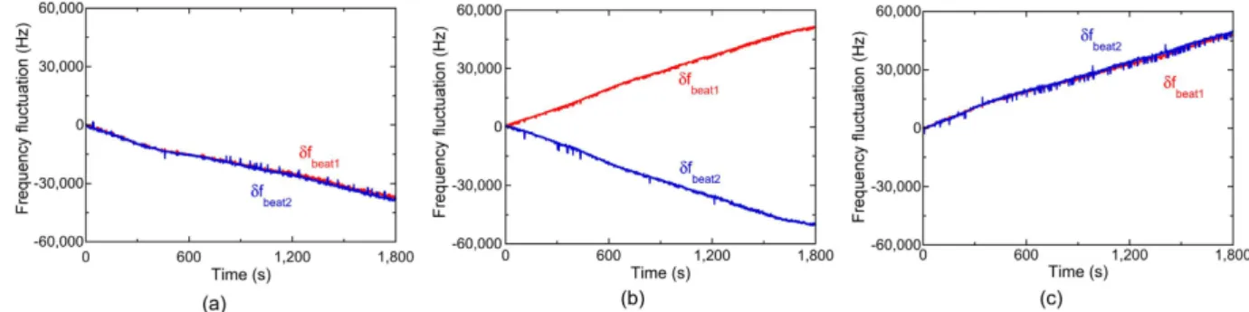
To confirm the three situations in Fig. 1, we measured fbeat1 and fbeat2 when fTHz was set at (a) 100,013,820,000 Hz
for fTHz < mfrep1 < mfrep2, (b) 100,016,340,000 Hz for mfrep1 < fTHz < mfrep2, and (c) 100,020,240,000 Hz for
mfrep1 < mfrep2 < fTHz. Figure 6 shows the temporal change of fbeat1 and fbeat2, where their frequency deviations from
the initial values are indicated by δfbeat1 and δfbeat2, when (a) fTHz < mfrep1 < mfrep2, (b) mfrep1 < fTHz < mfrep2, and (c) Figure 4. (a) Frequency fluctuations of frep1 and frep2 with respect to gate time. Temporal fluctuations of (b) δfrep1
and δfrep2 and (c) ∆frep.
Figure 5. Experimental setup of THz-comb-referenced frequency measurement. Dual-λ ML-FL,
free-running dual-λ mode-locked Er-doped fibre laser oscillator; CWDM-BPF, coarse-wavelength-division-multiplexing bandpass filter; EDFA1 and EDFA2, Er-doped fibre amplifiers; L, lens; PCA1, free-space-coupled, bowtie-shaped, low-temperature-grown (LT) InGaAs/InAlAs photoconductive antenna; PCA2, fibre-coupled, dipole-shaped LT-InGaAs/InAlAs PCA detector; PD, photodetectors; M, double-balanced mixer; LPF, low-pass filter; AMP, current preamplifiers; LO, local oscillator; BS, beam splitters.
mfrep1 < mfrep2 < fTHz. In all graphs, fbeat1 and fbeat2 fluctuated monotonically due to the drift of frep1 and frep2 in the
free-running operation. However, the directions of the temporal fluctuations were different from each other. In Fig. 6(a and c), fbeat1 and fbeat2 indicated similar behaviour to each other, namely, a monotonic decrease or increase.
On the other hand, in Fig. 6(b), fbeat1 and fbeat2 changed in the opposite directions to each other, while their sum
remained constant. These behaviours correctly reflect three situations in Fig. 1 and Eq. (4). Finally, we could cor-rectly determine m to be all 3,119 in Fig. 6(a,b and c) based on Eqs (4 to 6).
Next, we measured frep1, frep2, fbeat1, and fbeat2 when fTHz was fixed at 100,020,240,000 Hz. After acquiring the
tem-poral waveforms for frep1, frep2, fbeat1, and fbeat2 at a sampling rate of 20 MHz, we calculated their mean values every
10 ms, which corresponds to a measurement rate of 100 Hz. Figure 7(a,b,c and d) show the temporal changes of the mean values for them. All values temporally fluctuated due to the free-running behaviour of the laser rather than the fluctuation of fTHz. By substituting frep1, frep2, fbeat1, and fbeat2 in Eqs (4 to 5), the value of m was determined
to be 3,119, as shown in Fig. 7(e). Finally, from Eq. (6), we determined the mean and standard deviation of fTHz to
be 100,020,239,860 Hz and 125 Hz in repetitive measurements of fTHz at a measurement rate of 100 Hz, as shown
in Fig. 7(f). Therefore, the relative accuracy and precision of the absolute frequency measurement were 1.4 × 10⁻⁹
and 1.2 × 10⁻⁹, respectively.
Figure 6. Temporal changes of δfbeat1 and δfbeat2 when (a) fTHz < mfrep1 < mfrep2, (b) mfrep1 < fTHz < mfrep2, and (c)
mfrep1 < mfrep2 < fTHz.
Figure 7. Temporal waveforms of (a) frep1, (b) frep2, (c) fbeat1, (d) fbeat2, (e) m, and (f) fTHz when fTHz was fixed at
Figure 8 shows the measurement precision with respect to the measurement rate and the corresponding meas-urement time. The measmeas-urement precision and the measmeas-urement rate showed a trade-off relation within a range of measurement rates from 1 to 100 Hz. However, the correct determination of fTHz was impossible at
measure-ment rates higher than 100 Hz, because the measuremeasure-ment error of the numerator | ± fbeat2 ± fbeat1| over the
denom-inator frep2 − frep1 in Eq. (5) makes it impossible to determine m correctly.
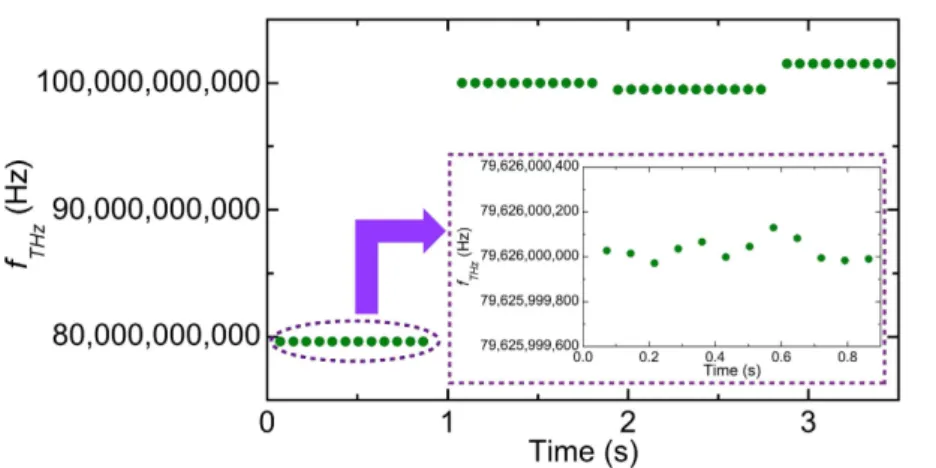
Finally, we performed real-time monitoring of fTHz when fTHz was changed suddenly or slightly. Figure 9 shows
the measured fTHz when the nominal frequency of the CW-THz test source was first set at 79,626,000,000 Hz,
increased by 20,395,080,000 Hz, decreased by 513,120,000 Hz, and then increased by 2,020,260,000 Hz. The measured fTHz at each frequency setting was determined to be 79,626,000,029 ± 47 Hz, 100,021,079,989 ± 32 Hz,
99,507,959,988 ± 26 Hz, and 101,528,219,978 ± 36 Hz, respectively. Even though fTHz changed across many modes
in the dual PC-THz combs, fTHz was determined correctly.
Discussion
One may wonder why such high precision was achieved in the real-time measurement of fTHz by using the
dual-PC-THz combs without the stabilization of frep1 and frep2. The reason is that each PC-THz comb always
functions as a frequency ruler with equal intervals and a linear scale regardless of whether or not frep1 and frep2 are
stabilized. Such characteristics are inherent in frequency combs. Only if the temporal waveforms for frep1, frep2,
fbeat1, and fbeat2, are acquired synchronously, fTHz can be determined without the influence of unstabilized frep1 and
frep2, as demonstrated in Figs 7(f) and 9.
The precision of 1.2 × 10⁻⁹ was achieved at a measurement rate of 100 Hz in the present setup; however, it was
100-times worse than that of the previous experiment with two independent free-running mode-locked lasers10.
In the instantaneous-frequency-calculation algorithm8, the precision is largely influenced by the signal-to-noise
ratio (SNR) of the beat signals with fbeat1 and fbeat210. The beat signals measured by LT-InGaAs/InAlAs PCAs in the
present setup showed the much lower SNR than the signals measured by LT-GaAs PCAs in the previous setup due to high dark-current noise in the LT-InGaAs/InAlAs PCAs (not shown). Therefore, the difference in precision between them arises from the low SNR in beat signals rather than use of the free-running dual-λ mode-locked Er:fibre lasers. In other words, there is still some room to enhance the precision by improving the PCAs.
Figure 8. Measurement precision with respect to the measurement rate and the corresponding measurement time.
Figure 9. Real-time monitoring of fTHz when fTHz was suddenly or slightly changed. Inset shows the
∆frep (= 1.63 kHz) in the dual-λ mode-locked fibre laser used here was relatively high compared with that
(typ-ically, less than several tens Hz) in dual mode-locked lasers used in the previous research10. In this case, we cannot
neglect the dead band in the determination of m. In Fig. 1 and Eqs. (1 to 6), it is assumed that the beat signals at the lowest frequency (freq. = fbeat1 and fbeat2) are generated by the same mode number m of dual PC-THz combs
(freq. = mfrep1 and mfrep2). The dead band is generated when fbeat1 and fbeat2 are generated by different mode numbers
of the dual PC-THz combs. Figure 10(a) shows the optical spectrum when fTHz exists within the dead band, namely
+ < < +
m f f f m f f
2 2 (7)
rep1 rep1 THz rep2 rep2
In this case, fbeat1 is generated by photoconductive mixing between fTHz and (m + 1)frep1, whereas fbeat2 is generated
by photoconductive mixing between fTHz and mfrep2. The dead bandwidth ∆fdead is given by
∆ = + − + = ∆ + f m f f m f f f m 2 2 1 2 (8)
dead rep2 rep2 rep1 rep1 rep
For example, when fTHz = 100 GHz, frep1 ≈ frep2 ≈ 32 MHz, ∆ frep = 1.63 kHz, and m = 3,125, ∆ fdead is estimated to be
around 5.09 MHz, which corresponds to 16% of the measurement window with the frequency range of frep1 or frep2.
Figure 10(b) shows the real-time monitoring result of fTHz when fTHz was linearly tuned from 100,024,770,463 Hz
to 100,044,423,685 Hz at a sweep rate of 19.653 MHz/s. One can confirm the measurement error of fTHz caused
by the dead band.
The simplest way to reduce the dead band is to reduce ∆frep. There is still some room to further reduce ∆frep of
the dual-λ mode-locked fibre laser down to a few hundred Hz by optimizing the fibre length and dispersion. In this case, it is expected that ∆fdead can be reduced to around 0.5 MHz, which corresponds to 1.6% of the
measure-ment window. Work is in progress to develop a dual-λ mode-locked fibre laser with lower ∆ frep.
Conclusions
We measured the absolute frequency of CW-THz radiation using dual PC-THz combs induced by a dual-λ mode-locked fibre laser. To the best of our knowledge, this is the first time such a laser system has been employed for frequency measurement in THz region. Although this laser was operating in the free-running mode with-out stabilization of frep1 and frep2, a relative precision and accuracy of 1.2 × 10⁻⁹ and 1.4 × 10⁻⁹ were achieved
at a measurement rate of 100 Hz due to the common-mode behaviour of frep1 and frep2, in addition to the fact
that the interval between the PC-THz comb modes was kept equal regardless of the fluctuation in frep1 and frep2.
Furthermore, an abrupt or slight change in fTHz could be accurately monitored due to the real-time capability Figure 10. (a) Dead band of fTHz determination. (b) Measurement errors in the real-time monitoring of fTHz
thanks to the use of dual PC-THz combs. Although the dual-λ mode-locked fibre laser was used in this work for measuring the frequency of CW-THz radiation in real time, it should be possible to apply it to THz spectroscopy and other metrology applications based on dual THz combs, such as ASOPS THz time-domain spectroscopy21–24,
dual THz comb spectroscopy25–27, and ASOPS THz impulse ranging28. In particular, the constant ∆f
rep in the
free-running operation will enable correct scale conversion of the time axis or frequency axis in these spectro-scopic applications. This dual-λ mode-locked fibre laser will open the door to enhance versatility and practicabil-ity in dual-THz-comb-based THz measurement systems.
Methods
Free-running, dual-λ mode-locked Er:fibre laser oscillator.
As shown in Fig. 2(a), the free-running, dual-λ mode-locked Er:fibre laser oscillator consists of a 980-nm pumped laser diode (LD), a 980/1550 nm wave-length-division multiplexer (WDM), a single-mode fibre (SMF), a 2 meter length of erbium-doped fibre (EDF, Changfei 1022), a polarization-independent optical isolator (ISO), a home-made single-wall carbon nanotube saturable absorber (SWNT-SA), a fibre-squeezer-based polarization controller (PC), a 90/10 fibre output coupler (OC), and an in-line polarizer (ILP) with two 0.25-meter-long polarization maintaining fibre (PMF) pigtails at both ends. The lengths of the commercial single-mode fibres (SMF-28 and HI 1060) in the cavity were estimated to be ~3.4 m and ~0.35 m, respectively, and therefore, the total dispersion was estimated to be ~0.063 ps/nm. The SWNT-SA had a transmittance of 24% at 1540 nm and was fabricated on an FC/APC ferrule from a ~0.27 wt% SWNT solution by using the optical deposition method. By introducing the ILP with its transmission aligned along the slow axis of the PMF into the ring fibre laser, birefringence-induced filtering and loss control effects enabled multi-wavelength lasing in the cavity12,13,19. With the adjustment of the intracavity polarization state,simultaneous mode-locking centred on the 1530-nm and 1560-nm regions could be realized. ∆frep was related to
the cavity dispersion of the fibre laser, whereas frep1 and frep2 were related to be the fibre length; their values can be
further adjusted by optimizing the fibre length and dispersion.
Real-time determination of f
THzwith dual PC-THz combs.
Figure 5 shows a schematic diagram ofthe setup for measuring the frequency of CW-THz radiation The amplified λ1 pulse light at frep1 from one EDFA
(EDFA1) was collimated in free space and then focused onto a gap in a free-space-coupled, bowtie-shaped, low-temperature-grown (LT) InGaAs/InAlAs PCA (PCA1, TERA15-BT3, Menlo Systems) by a lens (L), whereas the amplified λ2 pulse light at frep2 from the other EDFA (EDFA2) was directly fed into a fibre-coupled,
dipole-shaped LT-InGaAs/InAlAs PCA detector (PCA2, TERA 15-RX-FC, Menlo Systems) via an optical fibre. This resulted in the generation of dual PC THz combs: PC-THz comb 1 with a frequency spacing frep1 in PCA1
and PC-THz comb 2 with a frequency spacing frep2 in PCA2.
The CW-THz test source was an active frequency multiplier chain (Millitech AMC-10-R0000 with multiplica-tion factor = 6, tuning range = 75–110 GHz, and mean power = 2.5 mW), which amplified the output frequency of a microwave frequency synthesizer (Agilent E8257D, linewidth < 0.1 Hz) by a factor of six. Since this test source was phase-locked to a 10 MHz rubidium (Rb) frequency standard (Stanford Research Systems FS725, accuracy = 5 × 10⁻¹¹, stability = 2 × 10–11 at 1 s), its output was CW-THz radiation with a linewidth of less than
0.6 Hz and a frequency accuracy similar to that of the frequency standard. When the CW-THz radiation was inci-dent on both PCA1 and PCA2, photoconductive mixing between the CW-THz radiation and the dual PC-THz combs resulted in the output of a current signal from them. The current signals from PCA1 and PCA2 were amplified and filtered by current preamplifiers (AMP, bandwidth = 10 MHz, transimpedance gain = 105 V/A),
and the beat frequencies below half of frep1 or frep2 were extracted as fbeat1 and fbeat2.
Portions of light from the EDFAs were detected with photodetectors (PD, Thorlabs DET01CFC, freq. band-width = 1.2 GHz). Since the output signal from the PDs included a fundamental component and a series of har-monic components of frep1 or frep2 within the frequency bandwidth of the PDs, we selected the 30-th harmonic
component of frep1 or frep2, namely 30frep1 and 30frep2, in order to magnify the frequency fluctuation. The components
30frep1 and 30frep2 were electrically mixed with an output signal from a local oscillator (LO, fLO = 961,000,000.00 Hz)
using a double-balanced mixer (M), and the resulting beat signals 30frep1 − fLO and 30frep2 − fLO were extracted by
two low-pass filters (LPF). Temporal waveforms for fbeat1, fbeat2, 30frep1 − fLO, and 30frep2 − fLO were simultaneously
acquired by a digitizer (resolution = 14 bit, sampling rate = 20 MHz). From the temporal waveforms, we deter-mined instantaneous values of frep1, frep2, fbeat1, and fbeat2 using the instantaneous-frequency-calculation algorithm
involving a Fourier transform, digital frequency filtering, an inverse Fourier transform, a Hilbert transform, the time differential of the instantaneous phase, and signal averaging8. Finally, we determined f
THz by substituting
these values into Eqs. (4 to 6). Since the CW-THz test source, the local oscillator, and the clock signals of the dig-itizer shared a common time-base signal from the frequency standard, one can evaluate the relative precision of frequency measurement without the influence of the absolute precision of the frequency standard.
References
1. Akyildiz, I. F., Jornet, J. M. & Han, C. Terahertz band: Next frontier for wireless communications. Phys. Commun. 12, 16–32, 10.1016/j.phycom.2014.01.006 (2014).
2. Seeds, A. J. et al. Terahertz photonics for wireless communications. J. Lightwave Technol. 33, 579–587, 10.1109/JLT.2014.2355137 (2015). 3. Kumar, S. Recent progress in terahertz quantum cascade lasers. IEEE J. Sel. Top. Quantum Electron. 17, 38–47, 10.1109/
JSTQE.2010.2049735 (2011).
4. Ito, H. et al. Photonic generation of continuous THz wave using uni-traveling-carrier photodiode. J. Lightwave Technol. 23, 4016–4021, 10.1109/JLT.2005.858221 (2005).
5. Kohjiro, S. et al. A 0.2–0.5 THz single-band heterodyne receiver based on a photonic local oscillator and a superconductor-insulator-superconductor mixer. Appl. Phys. Lett. 93, 093508, 10.1063/1.2976311 (2008).
6. Yokoyama, S. et al. Terahertz spectrum analyzer based on a terahertz frequency comb. Opt. Express 16, 13052–13061, 10.1364/ OE.16.013052 (2008).
11th Conference on Lasers and Electro-Optics Pacific Rim. Busan, 26A3_7 (Institute of Electrical and Electronics Engineers, New York), 10.1109/CLEOPR.2015.7375947 (Aug. 2015).
14. Kieu, K. & Mansuripur, M. All-fiber bidirectional passively mode-locked ring laser. Opt. Lett. 33, 64–66, 10.1364/OL.33.000064 (2008). 15. Zhao, X. et al. Dual-wavelength, bidirectional single-wall carbon nanotube mode-locked fiber laser. IEEE Photon. Technol. Lett. 26,
1722–1725, 10.1109/LPT.2014.2332000 (2014).
16. Zhao, X. et al. Coherent dual-comb mode-locked fiber laser based on a birefringent ring cavity. Frontiers in Optics 2015, San Jose, FW3C.3 (Optical Society of America, Washington, D.C.), 10.1364/FIO.2015.FW3C.3 (Oct. 2015).
17. Liu, Y. et al. Unidirectional, dual-comb lasing under multiple pulse formation mechanisms in a passively mode-locked fiber ring laser. Opt. Express 24, 21392–21398, 10.1364/OE.24.021392 (2016).
18. Zhao, X. et al. Fast, long-scan-range pump-probe measurement based on asynchronous sampling using a dual-wavelength mode-locked fiber laser. Opt. Express 20, 25584–25589, 10.1364/OE.20.025584 (2012).
19. Zhao, X. et al. Picometer-resolution dual-comb spectroscopy with a free-running fiber laser. Opt. Express 24, 21833–21845, 10.1364/ OE.24.021833 (2016).
20. Zhao, X. et al. Coherent asynchronous sampling distance measurement using a single polarization-multiplexed ultrafast laser. 2014 Conference on Lasers and Electro-Optics. San Jose, STh4O.2 (Optical Society of America, Washington, D.C.), 10.1364/CLEO_SI.2014. STh4O.2 (Oct. 2015).
21. Janke, C. et al. Asynchronous optical sampling for high-speed characterization of integrated resonant terahertz sensors. Opt. Lett.
30, 1405–1407, 10.1364/OL.30.001405 (2005).
22. Yasui, T., Saneyoshi, E. & Araki, T. Asynchronous optical sampling terahertz time-domain spectroscopy for ultrahigh spectral resolution and rapid data acquisition. Appl. Phys. Lett. 87, 061101, 10.1063/1.2008379 (2005).
23. Yasui, T. et al. Super-resolution discrete Fourier transform spectroscopy beyond time window size limitation using precisely periodic pulsed radiation. Optica 2, 460–467, 10.1364/OPTICA.2.000460 (2015).
24. Hsieh, Y.-D. et al. Dynamic terahertz spectroscopy of gas molecules mixed with unwanted aerosol under atmospheric pressure using fibre-based asynchronous-optical-sampling terahertz time-domain spectroscopy. Sci. Rep. 6, 28114, 10.1038/srep28114 (2016). 25. Hsieh, Y.-D. et al. Terahertz comb spectroscopy traceable to microwave frequency standard. IEEE Trans. Terahertz Sci. Tech. 3,
322–330, 10.1109/TTHZ.2013.2250333 (2013).
26. Hsieh, Y.-D. et al. Spectrally interleaved, comb-mode-resolved spectroscopy using swept dual terahertz combs. Sci. Rep. 4, 3816, 10.1038/srep03816 (2014).
27. Yasui, T. et al. Adaptive sampling dual terahertz comb spectroscopy using dual free-running femtosecond lasers. Sci. Rep. 5, 10786, 10.1038/srep10786 (2015).
28. Yasui, T. et al. Absolute distance measurement of optically rough objects using asynchronous-optical-sampling terahertz impulse ranging. Appl. Opt. 49, 5262–5270, 10.1364/AO.49.005262 (2010).
Acknowledgements
The work at Beihang University was supported by the 973 Program (2012CB315601), NSFC (61521091/61435002) and with Fundamental Research Funds for the Central Universities, Beihang PhD Student Funds for Short-term Visiting Study and the Academic Excellence Foundation of BUAA for PhD Students. The work at Tokushima University was supported by the Exploratory Research for Advanced Technology (ERATO) MINOSHIMA Intelligent Optical Synthesizer Project, Japan Science and Technology Agency (JST), Japan.
Author Contributions
T.Y. and Z.Z. conceived the project. G.H., X.Z., Y.Y., C.L., and M.B. constructed the dual-λ mode-locked Er:fibre laser. G.H., Tat. Miz., Tak. Min., and Tak. Miz. performed the experiments and analysed the data. G.H., Z.Z., and T.Y. wrote the manuscript. All authors discussed the results and commented on the manuscript.
Additional Information
Competing financial interests: The authors declare no competing financial interests.
How to cite this article: Hu, G. et al. Measurement of absolute frequency of continuous-wave terahertz
radiation in real time using a free-running, dual-wavelength mode-locked, erbium-doped fibre laser. Sci. Rep. 7, 42082; doi: 10.1038/srep42082 (2017).
Publisher's note: Springer Nature remains neutral with regard to jurisdictional claims in published maps and
institutional affiliations.
This work is licensed under a Creative Commons Attribution 4.0 International License. The images or other third party material in this article are included in the article’s Creative Commons license, unless indicated otherwise in the credit line; if the material is not included under the Creative Commons license, users will need to obtain permission from the license holder to reproduce the material. To view a copy of this license, visit http://creativecommons.org/licenses/by/4.0/