Model Based Design Environment for the Embedded System
Case Study: Inverter Power Supply
By
MONA ABD EL-BASET ABO EL-DAHB
A THESIS
Submitted to the Department of Production Science and Technology, Graduate School of Engineering, Gunma University
in Partial Fulfillment of the Requirements for
the Degree of Doctor of Electrical and Computer Science Engineering
Under Supervision of Prof. WEI SHU GANG Prof. YOICHI SHIRAISHI
Department of Production Science and Technology Graduate School of Engineering
Kiryu-shi, Gunma, 376-8515, JAPAN September 2011
i
ACKNOWLEDGEMENTS
First of all, praise to ALLAH for all - it is the prime honor for me that ALLAH makes me Muslim and shows me the reality of this life. Also, I would like to declare my thanks for ALLAH for giving me the patience and perseverance to work through this research. I would like to express my deepest appreciation and thanks to the great Professor Yoichi
Shiraishi for his brilliant guidance, as well as his tremendous and earnest supervision, not
only throughout the duration of this period of study, but also in all my general life matters. He always gives his support for my spirit and teaches me well. He has been a very caring and helpful supervisor throughout the time of my study in Gunma University and residence in Japan. There is no doubt this is all from ALLAH and I wish I keep my communication with Prof. Yoichi for my future research as well as social activities. Special thanks extended to the Ministry of Higher Education in Egypt, Helwan University and all the staffs of Egyptian Culture Office in Tokyo to support me and my Ph D study in Japan.
Also, I would like to express my thanks to all the examiner committee of my thesis that includes Prof. Wei Shu Gang, Prof. Takeo Ishikawa, Prof. Kou Yamada and Prof. Toshikazu Matsui. Special thanks for Mis. Lida Tohidi, who is my family friend, for assisting in English revision of the written aspect of the thesis as well as my published papers.
I am also really grateful and highly appreciate for the support of all colleagues from Tokyo Sieden Company. A cordial thank you to everyone of Prof. Yoichi laboratory who gave me useful and helpful assistance, support, and cooperation in various ways during my study time. I would also like to express many thanks for all of the Gunma University staff for their help during my study.
I assign my profound and deepest thanks to my wonderful husband, Dr. Aly, for his devotion, support, patience, and encouragement. He provided the suitable atmosphere not only for my study but for my life. I would also like to thank my four wonderful kids, Fatama, Mohamed, Youssef and Ibrahim, who give me the happiness in this life.
ii
EXECUTIVE SUMMARY
Nowadays, an embedded system is becoming a main solution to most specific tasks in industrial and business fields because of its high stability, economic power consumption and usefulness in many fields. Every year, billions of microprocessors are sold for use in embedded systems. This is in sharp contrast to a few hundred million desktop processors that are sold in the same timeframe. From automobiles to medical equipments, thermostats to space shuttles, embedded systems are all around us. Basically the embedded system can be simply defined as a combination of hardware and software that are built into a product for purposes such as control, monitoring and communication without human intervention. Hardware includes microprocessor with additional attached external memory, I/O, and other components such as sensors, keyboard, LEDs, LCDs, and any kind of actuators. Embedded software is the driving force of an embedded system when it is loaded on the system, it will never be changed unless it needs to be reloaded or replaced. Embedded systems are considered one of the most difficult technical and commercial environments because there are many critical systems controlled by embedded system. It includes communication applications, transportation navigation, medical systems and financial systems. Failure or compromise of such systems can have significant consequences including disruption of critical services, financial loss and sometimes loss of life. Subsequently, both quality and performance of such system are considering vital issues.
In developing embedded systems, the requirements for software design are completely different than the case of software design in the business application field. In the embedded software design, ultra high reliability, real time process and hardware/software co-design are required. However, in the development of an embedded system, the amount of software increases explosively in a very short period. The designers of the embedded system face ever increasing challenges in the design stage. One of the difficulties of the embedded system design is that the hardware and the software of an embedded system are developed simultaneously. In the business system development, the hardware on which the software should be executed is available. For example in the business software development, the platform for executing software is a computer incorporating Intel's microprocessor and Windows operating system. However, in the embedded software design even the specifications of hardware usually are not completed embedded software cannot be tested. The embedded system software designer should wait until the hardware
iii
completed, thus software is tested in the actual prototypes. So, revealing the error in the embedded software is considered a critical step. Furthermore, the discovery of errors often resulted in production delay as well as additional expense can be added to the estimated product cost.
One of the major challenges in the design process of embedded systems is to accurately predict performance characteristics of the final system implementation in early design stages. Another challenge of the embedded system design is the system parameters optimization because embedded software controls hardware. Consequently, if the software is not accurately optimized then the embedded system may run out of control. Verification of the embedded system function, which is the process to verify that the system meet the required specification or not, is considered one of the most vital challenges of the embedded system design. In the traditional design method, it is reported that the verification period takes about 50% of the production time. In addition the complexity of the embedded system which arises due to the combination of more and more functions onto a single system. Building on the above descriptions, the complexity of the embedded system design in many applications has been dramatically increasing over the past few years. Therefore, most of researchers directed their attentions to solve some of those challenges. One of the leading techniques in this field is the Model Based Design method. In this method the model can be used to verify the system design and control algorithm. Furthermore, it can be used as executable specification for the designer before the actual implementation. The Model Based Design method is a new approach in the embedded system design and development. It only defines the design methodology and in actual applications, the problem is the definition and representation of each component of embedded system as a model. Once a model is defined in an application, the variations of the model can also be defined by the modification of the original model in other applications based on the reusability of object oriented programming. However, the usefulness of the Model Based Design method has not yet been verified in many applications. The objective of the study is to verify the usefulness, to find out the problems and to check the feasibility of the Model Based Design method.
This research contributes a novel technique that allows the full simulation of the embedded system in the virtual environment based on the Model Based Design method. We used the inverter power supply design as a case study of the application of the Model
iv
Based Design method. Inverter power supplies are widely used in many industrial processes and applications, such as, uninterruptable power supplies, motor control, and electric vehicle applications. It can be defined as a device that converts DC (Direct Current) from sources such as batteries, solar panels, fuel cells, or wind generations to AC (Alternative Current). So, the output can be used in a wide range of AC applications. Traditionally, an analog control technique is used to control the inverter power supply. However, due to the fact that a digital control technique can provide the benefits which cannot be provided by an analog one, a digital control starts to be a viable candidate in the inverter power supply design. Actually, a digital controller can offer a programmable solution for the applications. Moreover, it also offers the flexibility in design and an advanced algorithm as well as additional features can be added to the controlling software instead of hardware. From the electrical point of view, a digital controller is less sensitive to the environmental conditions and shows precise behaviors compared to analog counterparts. In this study the SH7047 microprocessor is used to control the generation of the PWM signal which control the operation of the inverter power supply. To improve the performances of the digital PWM pulses, a digital control technique should be used. The main duties of the inverter control system are to regulate the output voltage against all possible existing disturbances. In this study, to an inverter power supply, a controlling algorithm is newly proposed, which is two layer controller that includes the feedforword and PI controller. To implement a digital control technique in the inverter power supply, an embedded system must be developed. Now, in general, this kind of embedded system is manually developed and the embedded software developing and testing time takes around 50% from the entire developing cycle. Therefore, the Model Based Design method is strong necessary in the design of inverter power supply. The entire inverter power supply system model is constructed under the name of Model In the Loop Simulation (MILS) environment. MILS environment is divided in two main parts which are the controlled part (electric DC/DC and DC/AC circuits) and the control part consisting of the microcontroller and the embedded software. A full simulator of the inverter power supply including electric circuit model and the functional model of the microprocessor is developed by using the MATLAB and Simulink environment. The electric part is developed using the Simulink power block set. The control part is modeled by simulating the function of the microprocessor unit using the S-Function technique and the embedded system software was described as C-MEX files. All parameters and the behavior of the model were tested, optimized and analyzed graphically as well as mathematically. The
v
validity and usefulness of the MILS environment is verified by comparing the simulated results with the experimental results in the actual device. The actual prototype of inverter power supply has been fabricated using Renesas SH7047 microprocessor and the embedded software is implemented manually. The input DC voltage is 24V and the target AC output is 100 RMSV with frequency of 60 Hz.
The results show that the application of Model Based Design method can contribute to system development period reduction and guarantee robust system design. The developed models helped us to optimize software parameters and to validate control algorithm in the virtual environment. Moreover, the models can be used to study and analyze the behaviors of the system which meet the challenges of designing the embedded control system. The results show that the suggested models are promising and the models can be useful for optimizing the performances in developing the embedded software. On top of that, the Model Based Design method saved the time and cost by large percentage comparing to the traditional method of design.
vi TABLE OF CONTENTS ACKNOWLEDGEMENTS ...I EXECUTIVE SUMMARY ... II TABLE OF CONTENTS ... VI LIST OF TABLES ... IX LIST OF FIGURES ... X CHAPTER 1 ... 1 INTRODUCTION ... 1 1.1.GENERAL ... 1
1.2.DEFINITIONOFEMBEDDEDSYSTEMS ... 1
1.3.EMBEDDEDSYSTEMVERSUSGERNALPURPOSESYSTEM ... 3
1.4.EMEDDEDSYSTEMDESGINLIFECYCLE ... 5
1.5.CLASSIFICATIONOFEMBEDEDSYSTEMS ... 6
1.5.1 Classification Based of the Function and Required Performance ... 6
1.5.2. Classification Based on the Size ... 7
1.6.SCOPEOFRESEARCH ... 8
1.7.PURPOSEOFRESEARCH ... 9
1.8.THESISOUTLINES ... 11
REFERENCES ... 13
CHAPTER 2 ... 15
MODEL BASED DEVELOPMENT ... 15
2.1.INTRODUCTION ... 15
2.2.CHALLENGESOFTHEEMBEDDEDSYSTEMDESIGN ... 16
2.3HARDWARE/SOFWARECO-DESGIN ... 17
2.3.1 Hardware / Software Concept ... 17
2.4.MODELBASEDDESGIN ... 19
2.4.1. Executable Specifications ... 20
2.4.2. Design with Simulation ... 21
vii
REFERENCES ... 23
CHAPTER 3 ... 25
INVERTER POWER SUPPLY DESGIN ... 25
3.1. INTRODUCTION ... 25
3.2. TOPOLGIESOFTHEINVERTERPOWERSUPPLY ... 27
3.3. DIGITALCONTROLFORINVERTERPOWERSUPPLY ... 27
3.4. DESCRIPTIONOFTHEINVERTERPOWERSUPPLY ... 30
3.4.1. DC-DC Conversion ... 30
3.4.2. DC/AC Inverter ... 34
3.4.3. SH microprocessor ... 40
3.5.PULSEWIDTHMODULATION ... 45
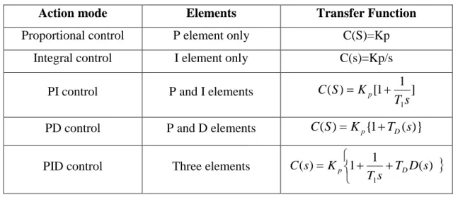
3.6.PIDCONTROLLER ... 48
REFERENCES ... 53
CHAPTER 4 ... 56
MODEL IN THE LOOP SIMULATION ... 56
4.1. INTRODUCTION ... 56
4.2. MATLAB/SIMULINKENVIRONMENT ... 56
4.3. MODELINTHELOOPSIMULATION,MILS ... 57
4.3.1 DC/DC and DC/AC Circuit Simulation ... 59
4.4. MICROPROCESSORSIMULATION ... 62 4.4.1. Control Algorithm ... 62 4.4.2. PWM Generation Program ... 66 4.5. S-FUNCTION ... 66 REFERENCES ... 70 CHAPTER 5 ... 71
EXPIRAMINTAL RESULTS AND DISCUSSIONS ... 71
5.1. INTRODUCTION ... 71
5.2. DC/DCCONVERTERPERFORMANCES ... 72
5.3.DC/ACINVERTERPERFORMANCES ... 75
viii
5.3.2. Pure Sine Wave Output Voltage and Frequency... 78
5.4.RESPONSEWITHLINEARLOAD ... 84
5.5.SUGGESTIONOFARTIFICALNEURALNETWOKAPPLICATION ... 90
REFERENCES ... 92
CHAPTER 6 ... 93
CONCLUSIONS AND RECOMMENDATIONS ... 93
6.1.CONCLUSIONS ... 93
6.2.RECOMMENDATIONFORFUTURESTUDY ... 94
6.2.1. MILS Quality Improvement ... 94
6.2.2. Optimization of Software Parameters Based on Neural Network ... 94
APPENDIX I ... 95
ix
LIST OF TABLES
Table 1. 1: Main export products of Japan ... 2
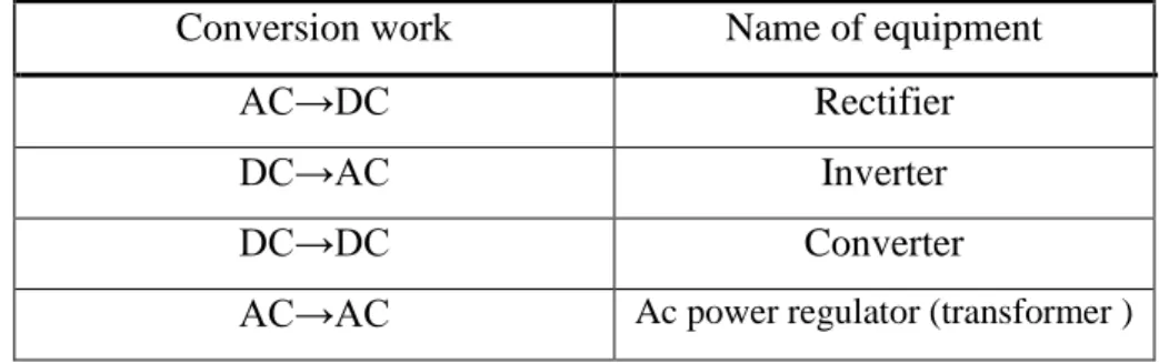
Table 3. 1: Types of power conversion ... 26
Table 3. 2: The pin configuration of the MMT ... 42
Table 3. 3: Action modes of the PID control ... 51
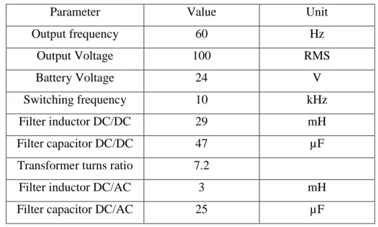
Table 4. 1: Specifications of the inverter circuits ... 61
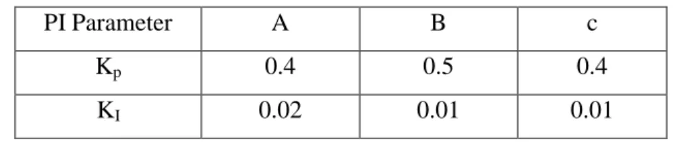
Table 5. 1: The three different cases a, b and c of the controlling parameters ... 75
x
LIST OF FIGURES
Fig.1. 1. Examples of embedded system ... 2
Fig.1. 2. Explosive increase in embedded software size ... 3
Fig.1. 3. Embedded system life cycle ... 5
Fig.1. 4. Difficulty of embedded software design ... 10
Fig.2. 1. Hardware/Software co-design technique ... 18
Fig.2. 2. Design processes of the Hardware/Software co-design ... 18
Fig.2. 3. Developing cycle of the embedded system ... 19
Fig.2. 4. Elements of Model Based Design ... 20
Fig.2. 5. Hardware In the Loop Testing ... 22
Fig.3. 1. Square, modified and pure sine wave inverter ... 27
Fig.3. 2 Developing cycle of the inverter power supply ... 28
Fig.3. 3 Conventional program development process ... 29
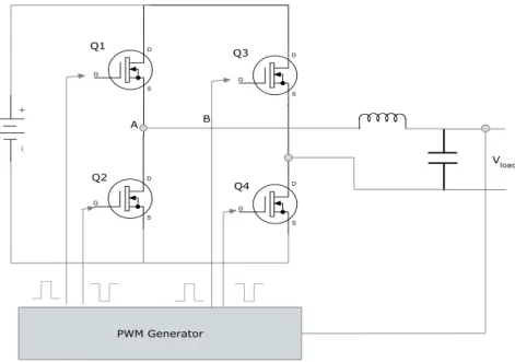
Fig.3. 4. Block diagram of inverter power supply ... 30
Fig.3. 5. Examples of the isolated DC/DC converter ... 32
Fig.3. 6. Circuit schematic of DC/DC converter ... 32
Fig.3. 7. Switching operation of DC/DC converter ... 33
Fig.3. 8. DC/DC switching operation ... 34
Fig.3. 9. DC/DC rectification and filtering operation ... 34
Fig.3. 10. Circuit schematic of DC/AC inverter ... 35
Fig.3. 11. Gate drive signals of the PWM inverters ... 36
Fig.3. 12. Relation between dead time and the voltage drop ... 37
Fig.3. 13. The relation between dead time value and the total harmonic distortion (THD)37 Fig.3. 14. Voltage and current distortion caused by the dead time ... 39
Fig.3. 15. Block diagram of SH microprocessor ... 41
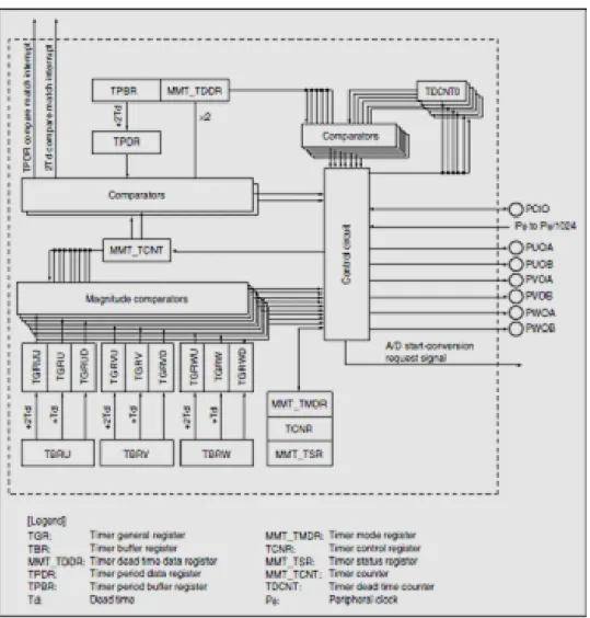
Fig.3. 16. Block diagram of MMT ... 42
Fig.3. 17. Example of PWM waveform generation from MMT unit ... 43
Fig.3. 18. Block diagram of MTU ... 44
Fig.3. 19. Analog PWM generation ... 46
Fig.3. 20. PWM outputs ... 47
Fig.3. 21. Microcontroller based PWM alignments ... 48
Fig.3. 22. Conventional feedback control system ... 50
xi
Fig.4. 1. Hierarchical models of complex control systems using Simulink ... 58
Fig.4. 2.Circuit schematic of inverter power supply ... 59
Fig.4. 3. SimPower system block set ... 59
Fig.4. 4. PWM generator block ... 60
Fig.4. 5. MATLAB model of open loop system ... 61
Fig.4. 6. Simplified block diagram of the proposed control system ... 63
Fig.4. 7. PI controller algorithm ... 65
Fig.4. 8. Block parameter dialog box of DC/DC S-Function ... 67
Fig.4. 9. S-Function parameter block ... 68
Fig.4. 10. Model In the Loop Simulation of inverter power supply ... 69
Fig.5. 1. Actual inverter power supply device ... 71
Fig.5. 2. Actual prototype circuits for the inverter power supply ... 72
Fig.5. 3. Actual control pulse in the DC/DC ... 73
Fig.5. 4. Simulated control pulses in DC/DC stage ... 73
Fig.5. 5. Principal of operation in DC/DC converter ... 74
Fig.5. 6. Simulation result of DC/DC converter ... 74
Fig.5. 7. Simulated AC output in case (a) ... 75
Fig.5. 8. Actual AC output in case (a) ... 76
Fig.5. 9. Simulated output in case (b) ... 76
Fig.5. 10. The actual output in case (b) ... 77
Fig.5. 11. The simulated result in case (c) ... 77
Fig.5. 12. The actual output in case (c) ... 78
Fig.5. 13. Actual sin wave output of inverter power supply ... 79
Fig.5. 14. The simulated sin wave output of inverter power supply ... 79
Fig.5. 15. Relation between the modulating signal and the generated pulses ... 80
Fig.5. 16. The actual control MTU pulses ... 81
Fig.5. 17. The actual MUT microprocessor output pulses ... 81
Fig.5. 18. The simulated MTU microprocessor unit pulses ... 82
Fig.5. 19. Actual sin wave output ... 82
Fig.5. 20. Simulated sin wave output ... 83
Fig.5. 21. The actual dead time value Td = 0.002ms ... 84
Fig.5. 22. The simulated value of the dead time ... 84
Fig.5. 23. Inverter power supply output with no load ... 85
xii
Fig.5. 25. The inverter power supply output with the linear load ... 86
Fig.5. 26. The inverter power supply output with the linear load in MILS ... 87
Fig.5. 27. Output of the inverter power supply with no load ... 88
Fig.5. 28. Output with the linear load ... 88
Fig.5. 29. Inverter power supply output with open loop ... 89
Fig.5. 30. Inverter power supply output with control algorithm ... 90
1
CHAPTER 1 INTRODUCTION
1.1. GENERAL
This chapter offers a brief introduction of the embedded systems; the difference between the embedded system and the general propose computer, embedded systems classification and the design challenges. Every year, billions of microprocessors are sold for use in embedded systems [1]. This is in sharp contrast to a few hundred million desktop processors that are sold in the same timeframe. From automobiles to medical equipments, thermostats to space shuttles, embedded systems are all around us. If you count how many computers you own or use probably one or two at work and another one or two at home. Now count the number of embedded systems you own or use, a digital cellular telephone, a pager, microwave oven, washer, dryer, dishwasher, coffee maker, refrigerator, VCR, television, video-game console, stereo receiver, CD player, DVD player, portable Discman, remote control for the TV, remote for the VCR, remote for the stereo, garage-door opener, automatic sprinkler timer, fax machine, PDA, answering machine, and so on. The modern automobile has about 100 embedded systems on it. Consequently, that is why embedded system design is a very important research field.
1.2. DEFINITION OF EMBEDDED SYSTEMS
An embedded system can be simply defined as a combination of hardware (microprocessor) and software that is built into a product for purposes such as control, monitoring and communication without human intervention [2, 3]. By other way, embedded system is a special-purpose computing device designed to perform dedicated functions, which consists of hardware and software. The hardware includes a microprocessor or microcontroller with additional attached external memory, I/O, and other components such as sensors, keypad, LEDs, LCDs, and any kind of actuators. The embedded software is the driving force of an embedded system. Once it is loaded it will never be changed unless it needs to be reloaded or replaced [4, 5]. Traditionally most of these systems are used for control and process measurement, as a side-effect of higher integration of integrated circuits more complex applications can be solved by embedded systems. Nowadays embedded systems can be found in devices from digital watch to communication systems, transportation navigation systems, medical systems, and financial
2
systems. Figure 1.1 shows some examples of the embedded systems applications.
Fig.1. 1. Examples of embedded system
The number of the embedded systems increases rapidly in the last few decades to meet modern life demands. For example in Japan, which is considered one of the most advanced country in the world, there are many products including the embedded system act as main export products such as automobiles, office equipments, copying machines. Table 1.1 shows the main export products in Japan (Japanese Ministry of Economy, Trade and Industry (METI)).
Table 1. 1: Main export products of Japan
Year 2000 2001 2002 2003 Total Cost* 516,542 489,792 521,080 545,484 1 Products Amount Ratio % Automobile 69,301 13.4 Automobile 72,108 14.7 Automobile 87,746 16.8 Automobile 88,756 16.3 2 Products Amount Ratio % Elec. Devices 45,758 8.9 Elec. Devices 36,474 7.4 Elec. Devices 38,673 7.4 Elec. Devices 40,745 7.5 3 Products Amount Ratio Office Equip 30,942 6.0 Office Equip 28,207 5.8 Office Equip 30,053 5.8 Office Equip 26,191 4.8 4 Products Amount Ratio Copy Machine 26,256 5.1 Copy Machine 25,045 5.1 Copy Machine 21,171 4.1 Copy Machine 20,660 3.8 Note: * hundred million yen
3
However, in the development of an embedded system, the amount of software increases explosively in a very short period as shown in Figure 1.2 and this causes a very serious problem in the embedded system industry. Japanese METI (Ministry of Economy, Trade and Industry) continues the investigations of the embedded system industry from 2004 and published the reports. From the latest report, the deficiency of embedded software designers reaches to about 94,000 in 2007. In the software development, the increase of the amount of lines of codes in an automobiles, mobiles phones, and digital home appliances makes the complexity of software design very much increased and the supply of embedded software engineers can not satisfy the needs of the current deficiency. Therefore, many studies are needed to overcome such problems.
Fig.1. 2. Explosive increase in embedded software size
1.3. EMBEDDED SYSTEM VERSUS GERNAL PURPOSE SYSTEM
An embedded system is usually classified as a system that has a set of predefined, specific functions to be performed and in which the resources are constrained [6]. For example cellular phones, it is an embedded system and it has several readily apparent functions as follows: the main function is to call and receive phone call perhaps several functions such as clock, alarm, and camera and so on. It also has several resource constraints as follows: Firstly, the processor that is operating the mobile phone cannot be very large, or else no one would use it. Secondly, the power consumption must be minimal, only a small battery can be contained in that cellular phone. Finally, it must perform its Function accurately. Each embedded system design satisfies its own set of functions and constraints. By comparing this example with the general propose computer we can see the differences. In this section the main differences between both systems are described below:
4
1. Embedded systems are dedicated to specific tasks, where PCs are general computing platforms. Embedded system is programmed to perform specific tasks conversely. General computer is able to perform unlimited tasks or a general-purpose computer, for example, you can install any software to do all kinds of jobs such as word processing, data sheet, database management, and others depending on your purposes.
2. Embedded systems are usually cost sensitive because the embedded system is only part of the whole product. Subsequently, if the cost of the embedded system reduces you can potentially reduce the product cost.
3. The implication of software failure are much more severe in the embedded systems than the general propose computer. It is considered one of the most difficult technical and commercial environments because many critical systems are controlled by embedded computer system. These include communication systems, transportation navigation systems, medical systems, and financial systems. Failure or compromise of such system can have significant consequences including disruption of critical services, financial loss, and loss of life.
4. Embedded systems have power constrains. This is not practically serious constraint for the general computer system. However, consider an embedded system connected to medical system in the ambulance, so the system must work reliably and for long time in a set of small batteries. So, it is very important issue to keep the embedded system running on minute amount of power.
5. Embedded systems have real time constrains. Real time constrains generally are grouped into categories depending on the application as follows: the first category is time sensitive constraints and; the second category is time critical constraints. If the application has time critical constraints the task must take place within a set window of time, controlling the flight worthiness of an aircraft is a good example of this. 6. Embedded systems must operate under extreme environmental conditions. The
embedded systems are everywhere, so the system must be designed to work well in different environment conditions and in the harsh environment as well.
5
1.4. EMEDDED SYSTEM DESGIN LIFE CYCLE
Aforementioned, the embedded system is a system which designed to perform a dedicated function, typically with tight real-time constraints, limited dimensions, and low cost and low-power consumption requirements. It is a combination of computer hardware and software and additional mechanical, optical, or other parts that are typically used in the specific role of actuators, sensors, and transducers [5, 7, 8]. In general the design life cycle of the embedded systems is unlike the design life cycle for the standard platform. The traditional design cycle of the embedded system can be summarized in the following phases [5].
1. Production specification,
2. Partitioning of the design into its software and hardware components, 3. Iteration and refinement of the partitioning,
4. Independent hardware and software design tasks, 5. Integration of the hardware and software components, 6. Product testing and release,
7. Ongoing maintenance and upgrading.
The percentage of the project time spent in each stage of the embedded system design life cycle is shown in Figure 1.3.
Fig.1. 3. Embedded system life cycle
In general, in the business software development, the platform for executing and testing the software computer is an easy task. However in the embedded system, an embedded system cannot be tested in the actual hardware. The software designer needs to wait until the hardware is completed then they can test the software which increases the product cost and time as well as it will affect the system quality. So, the developing cycle must have
37% 20% 31% 12% System specification &design HW&SW Design Prototype Debug System Test 51% of time
6
special tools and method to manage the complexity of the design. Thus, there are many challenges face the embedded system design which are described in details in the next chapter.
1.5. CLASSIFICATION OF EMBEDED SYSTEMS
Embedded systems can be classified into different categories based on its Function, the required performance of the application and the size of the system. The classification presented below in details.
1.5.1 Classification Based of the Function and Required Performance
An embedded system is becoming a main solution to most specific tasks because of its high stability, economic power consumption and usefulness. It is widely used in a range of applications in our life. The function of the embedded system varies from application to other application. The functions of the embedded system can be classified as follows:
Stand-alone embedded systems
In this category the embedded system works by itself and it is a self-contained device. It takes either digital or analog inputs from its input ports then it processes this data to get specific output. Then it outputs the resulting data to its attached output device, which either displays data, or controls and drives the attached devices. Entertainment devices such as video game console and MP3 players, digital cameras, and microwaves are typical systems that fall into this category [9].
Real-time embedded systems
In this category, the time is considered as a critical factor. In other words, some specific functions must be done in particular period. There are two types of real-time embedded systems hard time and soft time embedded systems. In hard real-time systems if the task is completed after the deadline it may lead to critical failure and in some case it may result in loss of life. For example, a car airbag control system, if any delayed reaction in this system can cause severe results. The response time deadline for the hard real time system is very critical (in millisecond or even shorter). It is very important for such system to react to an event within a strict deadline, and missing a deadline will constitute failure of the system. The hardware and software of hard real-time systems must allow a worst case execution (WCET) analysis that guarantees the execution be completed within a strict deadline [10,11,12]. The second group for the real time embedded system is the soft real-time system, in this system it
7
can tolerate with some degrees of the time missing. In this system, if the task is completed after the deadline, the system can continue work but only the quality of the system will reduce. For example the microwaves and the washing machines, in this example, the time for completing the task can be delaying with second without causing any critical problems .
Networked embedded systems
The networked embedded system is considered one of the fastest growing areas in embedded systems applications. The networked embedded systems connect to a network with network interfaces to access resources. The connected network can be Local Area Network (LAN), Wide Area Network (WAN), or the Internet. The connection can be wired or wireless [13]. Home security systems are one example of this group.
1.5.2. Classification Based on the Size
For different applications the scale of the embedded systems are varied. We can classify the embedded system based on the size as follows:
Small scale embedded system is designed using a single 8 or 16 bit microcontroller. Most of the small scale embedded systems are battery operated. Usually, „C‟ language is used for developing these systems. „C‟ program compilation is done into the assembly, and executable codes are then appropriately located in the system memory [10,11]. The software has to fit within the memory available and keep in view the need to limit power dissipation when the system is running continuously.
Medium Scale Embedded Systems:
These systems are usually designed with a single or few 16 or 32 bit microcontrollers or Digital Single Processors (DSPs) or Reduced Instruction Set Computers (RISCs). These have both hardware and software complexities. For complex software design, there are the following programming tools: Real Time Operating System (RTOS), Source code engineering tool, Simulator, Debugger and Integrated Development Environment (IDE). Software tools also provide the solutions to the hardware complexities. An assembler is of a little use as a programming tool.
Sophisticated Embedded Systems:
Sophisticated embedded systems have enormous hardware and software complexities and may need scalable processors or configurable processors and programmable logic arrays. They are used for cutting edge applications that need hardware and software
8
co-design and integration in the final system. However, they are constrained by the processing speeds available in their hardware units. Certain software functions such as encryption and deciphering algorithms, discrete cosine transformation and inverse transformation algorithms, TCP/IP protocol stacking and network driver functions are implemented in the hardware to obtain additional speeds by saving time. Some of the functions of the hardware resources in the system are also implemented by the software. Development tools for these systems may not be readily available at a reasonable cost or may not be available at all [10,11].
1.6. SCOPE OF RESEARCH
Embedded systems are considered one of the most difficult technical and commercial environments because many critical systems are controlled by embedded system including communication applications, transportation navigation, medical systems and financial systems. Failure or compromise of such systems can have significant consequences including disruption of critical services, financial loss and sometimes loss of life so the quality and the performance of such system are considering vital issues [8]. Building on this the focus of most researchers nowadays is directed to solve the challenges which face the embedded system. These challenges presented below:
1. The complexity of the embedded system, which arises due to the combination of more and more functions onto a single system.
2. The optimization: the software and the hardware parameter of the embedded system have to be optimized in very accurate way and also have to be on time. 3. Verification of the embedded system function, which is the process verify that the
system meet the required specification or not. In the traditional design method it is reported that the verification period takes about 50% of the production time.
Many of researchers nowadays try to develop new technique to overcome such challenges. One of the leading techniques in this field is the Model Based Design method. This study will test how the model based design put a good solution for the embedded system challenges. In this research, one case study was taken as an embedded system example which is the inverter power supply. Due the fact that a digital controller can provide more benefits which cannot be provided by the analog one in the inverter power supply applications, the digital control starts to be used. However, developing the inverter power supply based on the digital control faces some challenges which listed below:
9
1. It is so difficult to monitor the control algorithm behavior before the actual implementation.
2. The embedded software which controls the operation of the inverter power supply is developed manually which takes much time and bugs in such program are inevitable.
3. Bugs discovery is considered a critical problem and it results in production delay time and additional cost will be added.
4. Within the scope of our investigation, all the previous study concentrated on the modeling of the analog part and the digital pulse was generated by pulse generator. So, in the actual implementation, the software is needed to be tested in the actual prototype which may lead to system failure as well as it takes so much time to obtain the optimum parameters. And when any change occurred in the embedded software, the verification process is needed to start from the beginning. It is takes long time to optimize the software parameters using the conventional design method.
5. It is reported that the verification of the system performance and the control algorithm for the embedded system takes from 50 to 70 % of the production time.
So, in this research, entire virtual environment for the inverter power supply was constructed based on Model Based Design technique. The entire embedded system model is constructed under the name of Model In the Loop Simulation (MILS) environment. The embedded software is designed and optimized in the virtual environment using the MATLAB and Simulink environment. Newly applied controlling algorithm is designed and tested in the virtual system; this controlling algorithm consists of PI controller and the feedforward controller. Then to verify the validity of the proposed MILS environment, and to verify the control algorithm, a comparison between the virtual environment and conventional design method will be presented.
1.7. PURPOSE OF RESEARCH
In developing embedded systems, the requirements for software design are completely different in the case of software design as in the business application fields. In the embedded software design, ultra high reliability, real time process and hardware/software
10
co-design are required. Because of embedded software controls hardware, if the software is not accurately optimized then the embedded system runs out of control. One of the difficulties of embedded system design is that the hardware and the software of an embedded system are developed simultaneously. In the business system development, the hardware on which the software should be executed is available as shown in Figure 1. 4. For example, in general, in the business software development, the platform for executing software is a computer incorporating Intel's microprocessor and Windows operating system. However, in the embedded software design, even the specifications of hardware usually are not completed. Therefore, embedded software cannot test on the actual platform until the completion of the hardware. This will cause the degradations of qualities of embedded software.
Fig.1. 4. Difficulty of embedded software design
In the Model Based Design (MBD) method the model acts as the heart of the developing process. This study aims to develop a virtual environment that can be used to test and optimize the embedded software parameters before the actual implementation. This environment will save the time and cost comparing to the traditional design method as well as reduces the possibility of any damage which can be occurred, when the software is tested and optimized in the actual prototype as in the traditional methods. We used the inverter power supply as case study of the embedded system. Traditionally, an analog control technique is used to control the inverter power supply. However, due to the fact that a digital control technique can provide the benefits which cannot be provided by an analog one, a digital control starts to be used [14, 15, 16, 17]. We used the SH microprocessor as a digital controller for the inverter power supply circuits.
11
This study proposes a new virtual environment to test and optimize the software parameters in the virtual environment before the actual implementation. This environment called the Model In the Loop Simulation (MILS). This virtual environment is divided into two main parts, the control part and the plant part. MATLAB and Simulink software package is used in the developing of this virtual environment. The functional model of the microprocessor is developed using the S-Function and C-MEX files. All the software parameters used in this model are optimized and tested. Such system needs control algorithm to be stabilized. So, this study proposes a newly applied two layer controlling algorithm including the PI controller plus feedforward control. The validity of the controlling algorithm is also tested in the virtual environment (MILS). Finally, the optimized software parameters and the proposed controlling algorithm are tested on the actual inverter power supply prototype which has been fabricated using the Renesas SH microcontroller.
1.8. THESIS OUTLINES
This thesis consisted of seven chapters as presented below:
Chapter 1 presents an introduction about the embedded system design and its challenges. This chapter also describes a brief background of the embedded system and the main difference between the embedded system design and the general propose computer system design. It also describes the design life cycle of the embedded system and finally some embedded system design challenges are discussed.
Chapter 2 presents the embedded system design tools. Model Based Design (MBD) technique and the advantages of using it in the early stage of design are described in this chapter. Also, MBD concept and methodology are presented in this chapter
Chapter 3 presents the description of the inverter power supply as an example of the embedded system and topologies of the inverter power supply design is presented. The digital control technique and its advantages and the methodology of design are also described in this chapter. As well as, the controlling algorithms which we proposed are described in this chapter.
Chapter 4 presents the description of the proposed environment of design which is the MILS of the inverter power supply under the MATLAB and Simulink environment.
12
Chapter 5 presents results of both experimental and simulation environments. The investigation of performances of inverter power supply as well as the verification of the proposed control algorithm is shown. Finally, the usefulness of the virtual environment model is verified.
Chapter 6 contains the main and specific conclusions obtained from this study and also highlights recommendations for future studies.
13
REFERENCES
[1] J. Turley. “Embedded processors by the numbers”, Website, Accessed in October, 2010, http://vault.embedded.com/1999/9905/9905turley.htm.
[2] T. Henzinger and J. Sifakis, “The Embedded System Design Challenge”, In the Proceedings of the 14th International Symposium on Formal Methods (FM), May 2006. [3] W. Hongxing and W. Tianmiao, “Curriculum of Embedded System for Software
Colleges”, In the Proceedings of the 2nd
IEEE, August 2006.
[4] B. Thomas, “Embedded Robotics: Mobile Robot Design and Application with Embedded system”, Springer- Verlag Hiedelerg Ltd. Co., 2006.
[5] A. S. Berger, “Embedded Systems Design: An Introduction to Processes, Tools & Techniques”, Group West Publishers, US, 2002.
[6] D. Stepner , N. Rajan and D. Hui, “Embedded Application Design Using a Real-time OS”, In proceeding of 36th Design Automation Conference, New Orleans, USA, pp.151-156, 21-25 Jun, 1999.
[7] P. J. Mosterman, “Model Based Design for the Embedded System”, Taylor & Franicis Group, LLC, Ltd. Co., 2010.
[8] M. A. El Dahb, S. Iino, Y. Shiraishi and M. Tatsuno, “Model Based Design of the Inverter Power Supply”, In the Proceeding of ICCAS-SICE 2009 International Conference, August 17-21, 2009.
[9] K. Qian, D. D. Haring and L. Cao, “Embedded Software Development with C”, Springer Dardrecht, London New York, Ltd. Co., 2009.
[10] L. Brush, “Trends in Digital Power Management: Power Converter and System Demand Characteristics”, In the Proceedings of the Twentieth annual IEEE Applied Power Electronic Conference, 2005.
[11] T. Wikmshurst, “An Introduction to the Design of Small Scale Embedded systems”, Palgrave Macmillan Co., Ltd., 2001.
[12] Q. Li and C. Yao, “Real Time Concept for Embedded System Design”, CMO Media LLC, Group West Co., Ltd., 2003.
[13] J. Gregory, P. William and J. Kaiser, “Principle of Embedded Networks Systems Design”, ISBN Publisher Co., Ltd., California, US, January, 2009.
[14] M. Trigg, H. Dehbonei and C. V. Nayar, “Digital Sinusoidal PWMs for a Micro-Controller Based Single-phase Inverter, Part1: Principles of Digital Sinusoidal PWM
14
Generation”, International Journal of Electronics, Vol.95, No.8. pp.819-840, August, 2008.
[15] Y. Xue, K. Baekhy and J. Bordonau, “Topologies of Single Phase Inverter for Small Distributed Power Generators: An Overview”, IEEE Transactions, Vol.19, No.5, pp.1305-1314, Sept., 2004.
[16] O. Pop, G. Chindris and A. Dulf, “Using DSP Technology for True Sine PWM Generators for Power Inverters”, In the Proceedings of the 27th International Spring Seminar, 13-16 May, 2004.
[17] C. Matthew, D. Hooman and C. V. Nayar, “Digital Sinusoidal PWM Generation Using a Low–Cost Micro-Controller Based Single–Phase Inverter”, IEEE Transactions, Vol.1, pp.390-396, September, 2005.
15
CHAPTER 2
MODEL BASED DEVELOPMENT
2.1. INTRODUCTION
Given competitive temporal and cost constrains, developing a product on time and within budget requires a systematic approach to design and realization. A systematic approach ensures that the final products meet the initial requirements and let engineering teams with different specialization work together and communicate between the stages in the overall processes. In addition the approach also ensures that the design process and the final product are documented for maintenance and future development. In the traditional approach, engineering teams observe strict boundaries between their design activities. Furthermore, they transfer the data by passing design documents back and forth. This approach has the following drawbacks:
1. Documents can be unwieldy and unsuitable for recording functionality of the system. 2. It is difficult to keep the documentation synchronized with the current state of design. 3. Once the design is approved, coding the application becomes a separate, manual
activity.
4. When the documents are used as deliverable and shared electronically, engineers often duplicate their efforts. It is difficult to trace the source of error along a paper trail. So it is considered as a waste of time and increases the product cost.
So, many researches now try to solve these problems by using computer aided design techniques which can be defined as the use of computer systems to assist in the creation, modification, analysis, and optimization of a design. There are many critical systems controlled by embedded system including communication applications, transportation navigation, medical systems and financial systems. Subsequently, embedded systems are considered one of the most difficult technical and commercial environments. Failure or error of such systems may lead to significant consequences including disruption of critical services, financial loss and sometimes loss of life. Thus, the quality and the performance of such systems are considering vital issues. So, the design method of the embedded system should be selected very carefully to meet the required specifications. But up to now, there are many challenges facing the embedded system development and some of these challenges are described in the next section.
16
2.2. CHALLENGES OF THE EMBEDDED SYSTEM DESIGN
Embedded system development tools have traditionally lagged behind tools for the development of general systems [1]. Unlike general systems, the design space for embedded systems is extremely large, so it is difficult to contain all of the facilities to specify, design, and test embedded systems. The number of embedded systems increased rapidly year by year and then the designers of the embedded system face ever increasing challenges in the design stage. Some of these challenges are listed below:
1. In the traditional design method of the embedded system, the hardware and the software of an embedded system are developed simultaneously which is a sharp contrast of the general or business system. In the business system development, the hardware on which the software should be executed is available. For example, in general, in the business software development, the software can be tested and modified in the computer. However, in the embedded software design, even the specifications of hardware usually are not completed. Therefore, embedded software cannot test on the actual platform until the completion of the hardware. This will cause the degradations of qualities of embedded software as well as increasing the process time [2].
2. In traditional development method, design took places early in the development process, and the software designer should wait until late in the process. Then the embedded software is tested in the actual prototype. So revealing the errors in the embedded software is considered a critical step. Furthermore, the discovery of errors often resulted in production delay as well as additional expense can be added to the product cost [2, 3].
3. One of the major challenges in the design process of embedded systems is to accurately predict performance characteristics of the final system implementation in the early design stages.
4. The complexity of the embedded system arises due to the combination of more and more functions onto a single system [2, 4]. For example, luxury vehicles produced today contains more than 90 embedded electronic control units (ECU), which execute more than 10 million lines of computer codes which control many different functions in a car [5]. Increase of system complexity may lead to the increase of a project time and the system design cost.
17
systems and the embedded computer systems is that the hardware on which the software should be executed is unavailable. Therefore, a simulator of the embedded hardware is very useful for the development of the embedded software but it becomes a difficult matter because of the length of time required to build a simulator [2-4]. 6. Verification is the process of determining whether a system satisfies a given property
of interest or not. It is considered one of the most difficult challenges of the embedded system. Due to the fact that the embedded systems deal with very critical applications, a designer has to make sure that the system meets the required specification perfectly. It is reported that the verification takes more than 50 to 70% of the project time and the cost for verification of the embedded system is increasing rapidly [1].
7. As a result, the competition between the companies to deliver the product to the market faster and with lower cost, in most cases, the embedded system is a part of much larger product. Thus, any delay in the embedded system development will causes overall delay in the project or products.
However, nowadays embedded systems have garnered more interest in the research community, as well as there being an increased need for those embedded systems. Increasing the embedded system challenges open a wide range of research in the developing tools. Most of researchers try to find design tools that can solve some of the embedded system challenges mentioned above. This chapter presents some of the popular embedded systems design tools.
2.3 HARDWARE / SOFWARE CO-DESGIN
One of the methodologies gained a wide acceptance in both the embedded world and the general purpose world is that of Hardware/Software Co-design. Figure 2.1 presents the description of the Hardware/Software co-design technique.
2.3.1 Hardware / Software Concept
In the traditional design method, the designers have to portion the system into hardware and software parts and each part is developed separately [6, 7]. The hardware designer usually makes the architecture based on the knowledge of the hardware requirements. While the software designer faces many difficulties to fix the software due to the shortage of knowledge and software understandings. The result is that often the software designers are forced to make up for problems in the hardware through additional work of the
18
software, often leading to a less than optimal overall design of the system. The concept of Hardware/Software Co-design is that of both hardware and software designers worked in parallel to develop a system [7]. The designers define requirements and create a working specification. Then the hardware and software designers work together to map this specification on hardware and software architectures as shown is Figure 2. 2.
Fig.2. 1. Hardware/Software co-design technique
In this method the software design should wait until the hardware specification is fixed then they can test software. So, revealing the errors in the embedded software is considered critical step. In addition to the discovery of errors, it is often resulted in production delay as well as additional expense can be added to the product cost. Recently, many researchers try to find new methods that can reduce the suspension time for the software designer as shown in Figure 2. 2.
19 2.4. MODEL BASED DESGIN
Currently, many researches are focused on determining a good way to eliminate the challenges of the embedded systems design. Embedded systems have particularly tight performance, time to market, and cost constraint. To meet these constraints, researchers try to find solutions to efficiently design the systems with required performances. Recently, Model Based Design method is considered as one of the chief technique in this field. The Model Based Design method is considered one of the leading techniques as a solution of those challenges. In this method, the model can be used to verify the plant design and the control algorithm. MBD method puts a system model at the center of the development process, from requirement development through design implementation. Figure 2. 3 shows an example of the embedded control V Diagram which is often used to describe the development cycle of the embedded systems. Several versions of these diagrams can be found to describe variety of product design cycle. The figure from left to right describes the general propagation of the development steps. The main target of the Model Based Design method is to improve the development cycle by minimizing the iterations required for the design. If we consider the X axis of the diagram to represent the time, so the main goal is to narrow the V shape as much as possible by drawing the two legs of the diagram closer [8].
Fig.2. 3. Developing cycle of the embedded system
The system specifications phase is started by the analysis and the documentation of the system requirements. In the traditional method, this step is accomplished using paper based method which results in poor communication in the design process, errors in the design as well as limited traceability between the design and the requirements. In the
System Definition Modeling & Simulation System Testing Rapid Prototype Targeting Hardware-in-the Loop Testing
20
MBD method, the model can provide an excellent virtual environment for high level descriptions of the embedded system as shown in Figure 2. 4. This figure illustrates the main four elements of the MBD method. Description for elements of Model Based Design method is presented below.
Fig.2. 4. Elements of Model Based Design
2.4.1. Executable Specifications
As designs become larger and more complicated, it becomes necessary to first describe them at a high level of abstraction. For example, Simulink can provide specific blocksets such as signal processing, communication, video and image processing block set to help the designer to build abstraction model. This model provides a documented method for verifying and validating of design prior to move the development in actual controllers and hardware [8,9]. System engineers usually develop this high-level description for several purposes as listed below:
1. It enables designers to perform simulations by directly executing the model.
2. It is used throughout the development process for testing, verification, and implementation.
3. It allows for developers to identify bugs early on and avoid costly bug discovery towards the end of development.
Models Exceutable Specfication from Models Design with Simulation Implementation Continous Test and Verification
21
4. It eliminates the need for paper-based specifications, which is easily prone to misinterpretations, and replaces it with the executable specification.
5. Each member of a design team can understand and execute the model and can focus in developing parts of the main model [10,11].
A key point of shrinking the V embedded diagram by applying the MBD method is to begin developing the embedded control algorithm as early in the design cycle. In this stage, the model provides the ability to begin simulation of the control behaviors while the hardware prototype is still under development. In addition, the model can be reused for further modification of the same product which reduces the effort necessary to build the model again.
2.4.2. Design with Simulation
When designing the executable specification, the system engineer generally does not keep the implementation details in mind, but rather designs the algorithm to match the behavioral requirements for the system. Once the system engineer submits the executable specification to the development team, the team may need to make modifications to it in order to fit the design into a real world that may have limited resources, such as memory or processing power. These modifications may cause the output of the new design to deviate from the original design. Design engineers should decide if the deviation is acceptable. In this section, modifications to the algorithm will be done to make it suitable for hardware implementation and demonstrate how to continuously verify the design against the executable specifications. For example, if the designers need to change the controlling algorithm to meet the requirements, MBD method provides an environment where the designer can redesign the control algorithms and validate it in very short time comparing to traditional method of design [11].
2.4.3. Implementation and Testing
The modern Model Based Design tools provide automatic generation for both prototype and production codes directly from the model. So, all the design changes automatically flow through the final implementation. This process results in significant time and cost saving due to the inherent reproducibility and testability of the generated codes and elimination of communication errors [11,12]. In the Hardware in The Loop (HIL) Testing, the designer can test the real time behaviors and characteristics of the final system to verify the system control without the need for the physical hardware or operational
22
environment as shown in Figure 2. 5. HIL Testing can save the time with significant ratio comparing to the traditional design method. As well as, it is easy to implement comparing to physical prototype production. Up to this moment, the Model Based Design process does not completely eliminate the need for testing in the actual prototype, but it offers several opportunities to reduce the time needed to the testing stage [13,14,15,16].
Fig.2. 5. Hardware In the Loop Testing
Generally, it can conclude that the Model Based Design method will reduce the number of the development stages by combining the design, implementation, and testing into one process. The reduction of the required step comparing to the traditional method of design will result in better project management and mitigate the system development risk. The system design using this approach will reach the market faster and the end up costing will less than that of the system designed using the traditional method. Subsequently, the use of the Model Based Design method can provide numerous advantages over the traditional design method. Therefore, this study investigates how the Model Based Design method can provide such advantages by applying and building a new virtual environment for the embedded system design. Inverter power supply is used as a case study of the embedded system in this research.
Output hardware (A/D, discrete, serial) Input Software Inputs Hardware-in-the-loop-simulator Truth or physics model software Outputs Input hardware (A/D, discrete, serial) Output Software Outputs of embedded system Inputs of simulator Outputs of simulator Inputs of embedded system Embedded Computer HIL Simulator
23
REFERENCES
[1] M. Charistopher, “An Evaluation of Embedded System Behavior”. M.Sc Thesis, Department of Electrical and Computing Engineering, University of Maryland, 2000. [2] V. Woodward and J. Mosterman, “Challenges for Embedded Software Development”.
In the Proceeding of Circuit and System, MWSCAS Conference, pp.630-633, 5-8 August, 2007.
[3] B. Manfred, “Challenges in Automotive Software Engineering”, In the Proceedings of ICSE‟06 Conference, May20-28th, 2006.
[4] A. Madhukar and I. Lee, “Challenges and Opportunities in Deeply Embedded System Security”, ACM SIGBED Journal, New York, USA, Vol. 5, January, 2008.
[5] L. Ming-Shan, “Application of Embedded System in Construction Machinery”, In the Proceedings of the 8th ACIS international Conference, 30th July-1st August, 2007. [6] M. A. El Dahb,S. Iino,Y. Shiraishi and M. Tatsuno, “Model Based Design of
Inverter Power Supply”, In the Proceeding of ICCAS-SICE International Joint Conference, Fukouka, Japan, August 17-21, 2009.
[7] J. Hennessy and M. Heinrich, “Hardware/Software Co-design of Processors Concept Examples”, Lecture Notes Presented at Advanced Study Institute (ASI), Temezzo, Italy, June, 1995.
[8] J. Rautio, “Shortening the Design Cycle”, Microwave Magazine, IEEE, Vol.9, No.6, pp.86-96, Dec., 2008.
[9] D. Stepner, N. Rajac and D. Hui, “Embedded Application Design Using a Real-time OS”, In proceeding of the 36th of Design Automation Conference, New Orleans UAS, pp. 151-156, 21-25 June 1999.
[10] P. J. Mosterman, “Model Based Design for Embedded System”, Taylor &Francis Group Co., Ltd., New York, 2010.
[11] A. Behboodian, “Model Based Design”, DSP Magazine, Vol.2, pp.52-56, May, 2006. [12] C. Davey and J. Friedman, “Software Engineering with Model-Based Design”, In the
Proceedings of the Fourth International Workshop on Software Engineering for Automotive System, 2007.
[13] K. I. El-Far and J. A. Whittaker, “Model Based Software Testing”, Encyclopedia on Software Engineering, 2001.
24
[14] T. Erkkinen, “Automatic Flight Code Generation with Integrated Static Run Time Error Checking and Code Analysis”, In the Proceedings of AIAA Modelling and Simulation Conference and Exhibit, Colorado, August 21-24th, 2006.
[15] J. Zhenhua, R. A. Dougl and R. Leonard, “Hardware In the Loop Testing of Digital Power Controllers”, In the Proceeding of Applied Power Electronic Conference, April 18th, 2006.
[16] X Wu, H. Fifueroa and A. Mont, “Testing of Digital Controller Using Real Time Hardware in the Loop Simulation”, In the Proceeding of Power Electronic Specialists Conference, IEEE, Vol.5 , pp.3622-3627, April, 2006.
25
CHAPTER 3
INVERTER POWER SUPPLY DESGIN
3.1. INTRODUCTION
The development of new useful energy sources is the main key to continued industrial progress, and the continual improvement in the world‟s standard of living. Discovering new sources of energy, obtaining an essentially inexhaustible energy source, making it available everywhere, and converting it from one form to another without polluting and destroying the environment are some of the great challenges in the world today. One of these energy sources is to produces AC (Alternative Current) from fuel cell or solar panels output this device is called the inverter power supply system. In general, power conversion is the process which converts the electric current from AC or DC (Direct Current) power to provide a different electrical waveform. The term “converter” denotes a mechanism for either processing AC power into DC power (rectifier) or deriving power with an AC waveform from DC (inverter). Some converters serve both functions, others only one. Converters are used for such applications as follows:
Rectification from AC to supply electrochemical processes with large controlled levels of DC.
Rectification of AC to DC followed by inversion to a controlled frequency of AC to supply variable-speed AC motors.
Interfacing DC power sources (such as fuel cells and photoelectric devices) to AC distribution systems.
Production of DC from AC power for subway and streetcar systems, and for controlled DC voltage for speed-control of DC motors in numerous industrial applications.
Transmission of DC electric power between rectifier stations and inverter stations within AC generation and transmission networks.
26
Table 3. 1: Types of power conversion
Conversion work Name of equipment
AC→DC Rectifier
DC→AC Inverter
DC→DC Converter
AC→AC Ac power regulator (transformer )
In this study DC/AC conversion is investigated through the inverter power supply. Inverter power supplies are widely used in various kinds of applications, such as motor driver controllers [1, 2, 3], uninterruptible power supplies [4, 5], audio power amplifiers [6], and many other applications. It is a device that converts DC from sources such as batteries, solar panels, fuel cells, or wind generations to AC and then the output can be used in a wide range of AC applications [7]. The first generation of the inverter power supplies invented to get a square wave output. The use of such kind of inverter leads to many problems involving the functionality of the device that were being powered because those devices were designed to work with a sine wave source. Furthermore, the harsh edge of the square ware can cause some disturbances in the devices. Some hardware modifications were done in the square wave inverter to produce the modified square wave inverter. The modified square wave inverter provides a cheap and easy solution to powering the AC devices. But it has some drawbacks as it reduces the problem of the harsh edge of the square wave and it is not eliminating it. Moreover, not all the AC devices can work properly with such kind of inverter. A quantum leap occurs in an inverter power supply when it becomes possible to use the Pulse Width Modulation (PWM) technique to get the pure sine wave output. The PWM method allows for filtering undesirable harmonics in the output signals that is not possible in either square wave output or modified square wave output. Figure 3.1 shows the output signal for the square, modified square and pure sine wave output. Usually sine wave inverters are more expensive then modified sine wave generators due to the added circuitry. However, this cost is made up for in its ability to provide power to all AC electronic devices, to allow inductive loads to run faster and quieter, and to reduce the audible and electric noise in audio equipments.

![Figure 3.17 illustrates an example of the PWM pulse which is generated from the MMT unit [16]](https://thumb-ap.123doks.com/thumbv2/123deta/6233683.1091804/56.893.151.767.455.831/figure-illustrates-example-pwm-pulse-generated-mmt-unit.webp)