Spatially and temporally resolved
mass distribution in PEMFCs studied
by operando analytical methods
A Doctoral Thesis
Presented to Special Doctoral Program for Green
Energy Conversion Science and Technology
Faculty of Engineering
The Integrated Graduate School of Medicine,
Engineering, and Agricultural Science
University of Yamanashi
March, 2021
Contents
Chapter 1 General Introduction
1.1 Background ... 1
1.2 Polymer electrolyte fuel cells (PEFCs) ... 2
1.3 Various operando measurements of reaction distribution inside proton exchange membrane fuel cell (PEMFC) ... 6
1.4 Mechanisms to be investigated during power generation ... 7
1.5 Objective ... 9
References ... 10
Chapter 2 Visualization of the oxygen partial pressure during power
generation with low oxygen concentrations simulating
oxygen starvation
2.1 Introduction ... 172.2 Experimental 2.2.1 Visualization system ... 18
2.2.2 Calibration curves for oxygen partial pressure (p(O2)) ... 24
2.2.3 Power generation and cyclic voltammetry ... 26
2.2.4 p(O2) visualization ... 26
2.3 Results and discussion 2.3.1 I-V performance depending on the oxygen concentration ... 27
2.3.2 Visualization images of p(O2) distribution during power generation ... 28
2.4 Conclusion ... 41
Chapter 3 Oscillation mechanism based on operando p(O
2)
measurement using optical probes
3.1 Introduction ... 45
3.2 Instrument 3.2.1 Oxygen-sensitive dye film ... 48
3.2.2 Optical fiber ... 48
3.2.3 Oxygen monitoring system ... 49
3.2.4 Cell for the oxygen monitoring ... 54
3.2.5 Optical diagrams ... 55
3.3 Experiment 3.3.1 Cell preparation ... 56
3.3.2 p(O2) measurement ... 58
3.4 Results and discussion 3.4.1 Period and amplitude of voltage oscillation ... 59
3.4.2 p(O2) measurement in gas diffusion layers (GDLs) at different distances from catalyst layer ... 64
3.4.3 Oscillated p(O2) measured in GDLs without/with a micro porous layer (MPL) ... 67
3.4.4 Increase in p(O2) near outlet under the rib ... 70
3.4.5 Mechanism of synchronized oscillation of cell voltage and p(O2) ... 72
3.4.6 Oscillations under different conditions ... 75
3.5 Conclusions ... 76
Chapter 4 Neutron imaging of water distributions inside running
PEMFCs with Pt/CB and Pt/Nb-SnO
2as cathode catalysts
4.1 Introduction ... 80
4.2 Experimental 4.2.1 Transmission electron microscopy (TEM) and scanning ion microscopy (SIM) ... 82
4.2.2 Fuel cell assembly, activation, and cyclic voltammetry ...82
4.2.3 Calibration curve for water ... 83
4.2.4 Water imaging during power generation ... 83
4.2.5 Image analysis ... 84
4.3 Results and discussion 4.3.1 Cyclic voltammograms, TEM and SIM images ... 85
4.3.2 Neutron imaging during power generation ... 87
4.4 Conclusion ... 94
References ...95
Chapter 5 General conclusions
5.1 Summary of the thesis ... 975.2 Feasibility & Social significance ... 100
References ... 104
List of publications ... 105
Meeting abstracts ... 106
Awards ... 109
1
Chapter 1
General Introduction
1.1 Background
Electricity is indispensable to our lives. Home appliances, communication tools, PCs,
and other tools used both in private life and at work require electricity. However, conventional power generation methods emit CO2, a greenhouse gas. Before the 21st
century came, against the global warming, the Japanese government had been promoting nuclear power stations with no CO2 emission [1]. In 2010, the ratio of the nuclear power
in the total production of electricity in the country reached around 20%. However, in 2011, the Great East Japan Earthquake caused a meltdown of a nuclear reactor, and the safety of the nuclear power generation was questioned. In 2017, the ratio of the nuclear power in the production of electricity dropped to 3.1%. 80.8% of the Japan's power generation became from oil, coal, and LNG, therefore, the CO2 emission accordingly and abruptly
increased. Under this situation, the promotion of renewable energies, such as hydropower, wind power, solar power, and geothermal power, have been accelerated. However, the generation of renewable energies, based on the variable natural environment, is unstable [1]. Therefore, the social storage system of electricity is needed for the averaging of renewable energies. In order to solve this disadvantage, the rechargeable battery is commonly used, but it is not suitable for large-scale and long-term storages of electricity for various reasons, such as huge mass and volume and self-discharge. To compensate the use of batteries, hydrogen has been attracting attention in recent years. Hydrogen can be stably stored as a gas or liquid, and the transportation is relatively easy. At the present stage, hydrogen is generally produced from fossil fuels and biomass. Therefore, the CO2
2
emission is inevitable upon the use of hydrogen. The ultimate clean system with zero CO2
emission can be realized by the electrolysis of water to produce hydrogen, eventually used for the production of electricity [2].
Fuel cell is a device that converts chemical energy into electrical energy by supplying air (oxygen) and hydrogen first developed in 1839 [3]. Now, fuel cell is classified into four types: polymer electrolyte fuel cell (PEFC), solid oxide fuel cell (SOFC), molten carbonate fuel cell (MCFC), andphosphoric acid fuel cell (PAFC). The advantages of fuel cells are high efficiency, high power density (compactness), zero CO2 emission, and
quietness. Among the four types, PEFCs are used for vehicles andat residences because of low-temperature operation (50-100 ◦C), high energy conversion (40-60%), nearly zero
pollutants, and simple structure [4,5]. Residential fuel cell system, “ENE-FARM” was released from Panasonic Co., Ltd in 2009. The use of ENE-FARM, cogenerating the electricity and heat for hot water, results in the conversion efficiency of 95%. Fuel cell vehicle (FCV), “MIRAI” started to sale by Toyota Motor Corp. in 2014, followed by “CLARITY FUEL CELL” by Honda Motor Co., Ltd. in 2016. At the end of 2020, a new type “MIRAI” was at the market.
1.2 Polymer electrolyte fuel cells (PEFCs)
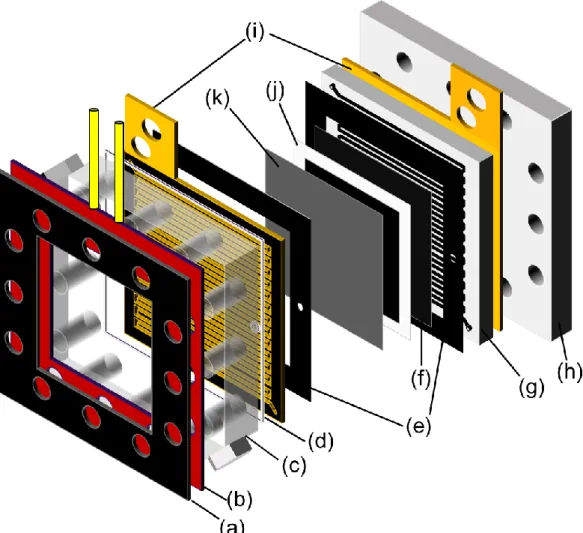
Among fuel cells, PEFCs most attract attention and are actively studied. As shown in Fig. 1-1, a single PEFC is constructed by sandwiching a membrane electrode assembly (MEA) with flow channels, current collector plates, and end plates on both sides. MEA is composed of a polymer electrolyte membrane (PEM), catalyst layers (CLs), and gas diffusion layers (GDLs).
3
(AEMs) exist. PEMs, perfluorosulfonated acid such as Nafion®(E. I. Du Pont Nemours
& Company, Inc.) as an example, are widely used due to their high conductivity and mechanical stability at varies temperatures and humidities. PEFCs using PEMs are named proton exchange membranes fuel cells (PEMFCs). In recent years, AEMs have been actively studied due to the larger reaction rate for the oxygen reduction reaction (ORR) and to the potential use of non-precious metals. Fuel cells using AEMs are named anion exchange membranes fuel cells (AEMFCs).
Pt catalyst is highly dispersed and supported on a carbon support with high specific surface area, such as TEC10E50E of TANAKA KIKINZOKU KOGYO K. K. The Pt particle size is 2-5 nm. An ionomer binder is mixed with a Pt catalyst for the transfers of ions from/to the electrolyte membrane to/from Pt catalyst surface.
Carbon paper and carbon cloth are generally used, such as 29BC of SIGRACET® of
SGL Carbon Group Co., Ltd., Germany and TGP-H060 of Toray Industries, Japan. In addition to gas permeability and conductivity, chemical and mechanical strengths are required. Polytetrafluoroethylene (PTFE) is added to the carbon fiber to improve water removal property. Micro porous layer (MPL) is commonly added at a GDL surface.
At the anode, hydrogen atoms are oxidized to protons (H+) to produce electrons (e-) on
the catalyst surface as shown in equation 1-1. The protons and electrons move to the cathode through the PEM and the external electrical load, respectively. At the cathode, the ORR occurs as shown in equation 1-2. The overall reaction is shown in equation 1-3.
Anode reaction: H2 → 2 H+ + 2 e- (eq. 1-1)
Cathode reaction: 1/2 O2 + 2 H+ + 2 e- → H2O (eq. 1-2)
4
The equilibrium cell voltage of a single PEMFC defined by the Nernst equation (eq. 1-4) is 1.23 V at the ambient temperature and pressure (25 oC, 100 kPa).
Nernst equation: 𝐸 = −∆𝑔̅(𝑇) 2∙𝐹 + 𝑅 ∙𝑇 2 ∙𝐹 ∙ ln 𝑝𝐻2∙ 𝑝𝑂20.5 𝑝𝐻2𝑂 (eq. 1-4)
where 𝑔̅ is the molar Gibbs free energy (J mol-1), T temperature (K), F Faraday constant
(96485 C mol-1), R universal gas constant (J mol-1 K-1), p partial pressure.
However, operating cell voltage of a single PEMFC is lower due to the overvoltages both at the anode and the cathode such as activation, ohmic, and concentration overvoltages as shown in Fig. 1-2. To reduce these overvoltages, catalyst, PEM and mass transport had been studied extensively. Understanding mass transport inside a PEMFC is especially important to improve the power generation performance and the durability in high current density. The mechanisms of various phenomena observed in the PEMFCs are also connected with mass transport. For analyzing mass transport, along with numerical simulations, operando analytical methods are essential using cells with practical structures.
5
Fig. 1-1 Schematic illustration of PEMFC. Proton Exchange Membranes Fuel Cell: PEMFC
6
1.3 Various operando measurements of reaction distribution inside proton exchange membrane fuel cell (PEMFC)
As described in chapter 1.1, the PEMFCs have already been commercialized. However, improving cell performance, durability and cost reduction are still mandatory for widely use. In order to improve the PEMFC performance and durability, understanding the inhomogeneous reaction distributions during power generation is necessary. Therefore, it is important to reveal the chemical (H2, O2, H2O, CO2, H2O2, etc.) and physical
(temperature, current density, gas flux, pressure etc.) parameters inside the PEMFC during power generation. In order to obtain these parameters, in-situ and operando measurement techniques, including visualization, are investigated. Among these parameters, the distribution and generation of liquid water have been successfully visualized by magnetic resonance imaging [6–8], optical observation [9–17], X-ray imaging [18–23], and neutron radiography imaging [24–34]. To achieve an understanding of the distribution of oxygen partial pressure (p(O2)) inside the fuel cell during cell
operation, the group in the University of Yamanashi developed a nondestructive real-time/space visualization system [14,35–42]. On the other hand, numerical simulation of these parameter inside the PEMFC have been studied to elucidate the transport phenomena with various cell component and under different operating conditions [43– 45]. The temperature distribution affects chemical kinetics and mass transports inside a PEMFC. The temperatures inside the MEAs have been measured by a thin film sensor [46], thermoelectric sensor [47], and thermograph [48]. The current density at the MEA in a single cell is also monitored to optimize the operating conditions and the cell designs with segmented current collectors [49–58] and by magnetomyography [59,60]. The degradation of carbon support material caused by start/stop cycle has been obtained by
7
the visualization of CO2 [61]. Additionally, the numerical simulations of these parameters
are conducted to elucidate the mass/energy transports with various cell components and under different operating condition [62,63]. The numerical simulation is widely used, especially in industrial fields. Although the numerical simulation is a powerful technique, unique phenomena have generally not been treated. Therefore, the experimental elucidation of those unique phenomena is very important.
1.4 Mechanisms to be investigated during power generation
A large number of gas starvation (hydrogen and oxygen) experiments have confirmed that the carbon support of the catalyst layer is corroded to CO2 [64–66]. Gas starvation
leads to the coalescence or loss of the catalyst on/from the electrode. The gas starvations are categorized to local gas starvation and overall gas starvation. In the overall gas starvation, the gas supply cannot meet the stoichiometric requirements of the fuel cell, as a result of which the external characteristics cannot follow the load changes due to the controller failure, variable load amplitude, or variable load speed during the load change. In the local gas starvation, uneven gas distribution on the surface of the electrode mainly due to the speed of gas transmission lagging behind the speed of current change, and there is no apparent performance on the external characteristics such as the output voltage of the fuel cell. The local gas starvation is frequently observed in the process of load change and is the main reason for the lifespan decay.
The hydrogen starvation is notorious as a major cause of the degradation of the CLs by the corrosion of carbon supports [67–69]. The reactions during the hydrogen starvation are 2H2O → O2 +4H+ + 4e- and C + 2H2O → CO2 + 4H+ + 4e-, resulting in the most
8
result in the electrical isolation of the platinum particles, which accelerates the agglomeration of the catalyst particles; the catalyst surface area is accordingly reduced.
The oxygen starvation has also been studied since the 2000s as a cause of irreversible catalyst degradation [70]. When oxygen starvation occurs at the cathode, the possible abnormal reaction formula is 2H + + 2e - → H
2. Especially in PEMFC stacks, this
abnormal reaction is enhanced to the hydrogen pumping. The existence of both hydrogen and oxygen at the same electrode surface lead to the degradation of catalyst and support material. The increasing concentrations of hydrogen even represent a flammability risk. The stability of PEMFCs during power generation is one of the most important issues especially for the operation at high current densities. Under certain conditions, the cell voltage and the current density become unstable and even fluctuated because of the instability of the reactions inside PEMFCs. Since the excess liquid water in a cell is one of the main sources of instability, the water management during power generation has been extensively studied [71,72]. The oscillation phenomena during power generation have been also reported in running PEMFCs [73–76]. The water generated by the power generation is continuously removed outside the fuel cell through the GDLs. However, when the water generation is too large, the flooding is inevitable. Materials must be developed, and the operating conditions and the cell configurations must be optimized.
For catalyst support, carbon is generally used. Recently, as alternative supports, ceramic materials have been developed, mainly for improving the durability [77–79]. Different support materials naturally change the chemical/physical properties of the catalyst layer, such as electroconductivity, mass transportation, and binder adsorption. The change in those parameters leads to the fuel cell performance [77–85]. Understanding the distributions of chemical/physical parameters with different supports is thus very
9
important for developing new supports.
1.5 Objectives
As described above, many unclear phenomena exist during power generation by PEMFCs. In my research, three selected mechanisms are analyzed by using operando measurement systems for p(O2) and liquid water by developing new analytical
apparatuses.
In Chapter 2, oxygen starvation is focused on. The current-voltage (I-V) performance suddenly decreased as the oxygen concentration/partial pressure decreased even under a high oxygen utilization. The p(O2) distribution on the GDL during power generation is
visualized in low oxygen concentration by using oxygen sensitive dye for the explanation of the mechanism.
In Chapter 3, a new mechanism of oscillation phenomena is presented. To elucidate the oscillation mechanism, a novel operando system for p(O2) by using optical probes was
developed.
In Chapter 4, a liquid water distribution inside single PEMFCs were visualized by neutron imaging. The current-voltage (I-V) performance of a PEMFC with Pt catalyst formed on Nb-doped SnO2 support (Pt/Nb-SnO2) was lower than that with Pt/CB. The
imaging of liquid water shed light on the difference in performances. Finally, these results are summarized, and suggest a feasibility of this study in Chapter 5.
10
References
[1] Japan’s Energy White paper 2020, by “Ministry of Economy, Trade and Industry”. https://www.enecho.meti.go.jp/about/whitepaper/2020pdf/
[2] Hydrogen energy white paper by New Energy and Industrial Technology Developed Organization (NEDO).
https://www.nedo.go.jp/library/ne_hakusyo_index.html
[3] W. R. Grove, Philosophical Magazine and Journal of Science 13:84 (1838) 430– 431.
[4] B. L. Yi, Fuel Cell-Principle, Technology & Application, Chemical Industry Press 238 (2003) 161–162.
[5] K. Rajashekara, A. K. Rathore, Electr. Power Compon. Syst. 43 (2015) 1376– 1387.
[6] S. Tsushima, K. Teranishi, S. Hirai, Electrochem. Solid-State Lett. 7 (2004) A269–A272.
[7] S. Tsushima, T. Nanjo, S. Hirai, ECS Trans. 11 (2007) 435–443.
[8] K. W. Feindel, S. H. Bergens, R. E. Wasylishen, J. Power Sources 173 (2007) 86–95.
[9] K. Tüber, D. Pócza, C. Hebling, J. Power Sources 124 (2003) 403–414.
[10] X. G. Yang, F. Y. Zhang, A. L. Lubawy, C. Y. Wang, Electrochem. Solid-State Lett. 7 (2004) A408–411.
[11] K. Sugiura, M. Nakata, T. Yodo, Y. Nishiguchi, M. Yamauchi, Y. Itoh, J. Power Sources 145 (2005) 526–533.
[12] K. Sugiura, T. Shiramizu, T. Yamauchi, M. Yamauchi, S. Matsuzaki, N. Kada, Y. Itoh, ECS Trans. 12 (2008) 131–138.
11
[13] X. Liu, H. Guo, C. Ma, J. Power Sources 156 (2006) 267–280.
[14] K. Takada, Y. Ishigami, S. Horataka, M. Uchida, Y. Nagumo, J. Inukai, H. Nishide, M. Watanabe, Electrochemistry 79 (2011) 388–391.
[15] K. Takada, Y. Ishigami, J. Inukai, Y. Nagumo, H. Takano, H. Nishide, M. Watanabe, J. Power Sources 196 (2011) 2635–2639.
[16] I. S. Hussaini, C. Wang, J. Power Sources 187 (2009) 444–451.
[17] P. K. Sinha, P. P. Mukherjee, C. Y. Wang, J. Mater. Chem. 17 (2007) 3089–3103. [18] S. J. Lee, N. Y. Lim, S. Kim, G. G. Parl, C. S. Kim, J. Power Sources 345 (2017)
67–77.
[19] F. Y. Zhang, S. G. Advani, A. K. Prasad, M. E. Boggs, S. P. Sullivan, T. P. Beebe, Electrochim. Acta. 54 (2009) 4025–4030.
[20] T. Sasabe, S. Tsushima, S. Hirai, K. Minami, K. Yada, ECS Trans. 25 (2009) 513–521.
[21] T. Sasabe, P. Deevanhxay, S. Tsushima, S. Hirai, J. Power Sources 196 (2011) 8197–8206.
[22] J. Lee, J. Hinebaugh, A. Bazylak, J. Power Sources 227 (2013) 123–130. [23] M. A. Hickner, N. P. Siegel, K. S. Chen, D. N. McBrayer, D. S. Hussey, D. L.
Jacobson, M. Arif, J. Electrochem. Soc. 153 (2006) A902–A908.
[24] Y. S. Chen, H. Peng, D. S. Hussey, D. L. Jacobson, D.T. Tran, T. Abdel-Baset, M. Biernacki, J. Power Sources 170 (2007) 376–386.
[25] H. Markötter, I. Manke, R. Kuhn, T. Arlt, N. Kardjilov, M. P. Hentschel, A. Kupsch, A. Lange, C. Hartnig, J. Scholta, J. Banhart, J. Power Sources 219 (2012) 120–125.
12
Kardjilov, H. Markötter, P. Shearing, D. J. L. Brett, J. Power Sources 412 (2019) 597–605.
[27] A. Turhan, K. Heller, J. S. Brenizer, M. M. Mench, J. Power Sources 180 (2008) 773–783.
[28] A. Z. Weber, M. A. Hickner, Electrochim. Acta. 53 (2008) 7668–7674.
[29] M. A. Hickner, N. P. Siegel, K. S. Chen, D. S. Hussey, D. L. Jacobson, J. Electrochem. Soc. 155 (2008) B294–B302.
[30] M. A. Hickner, N. P. Siegel, K. S. Chen, D. S. Hussey, D. L. Jacobson, M. Arif, J. Electrochem. Soc. 155 (2008) B427–B434.
[31] H. Murakawa, T. Ueda, T. Yoshida, K. Sugimoto, H. Asano, N. Takenaka, K. Mochiki, H. Iikura, R. Yasuda, M. Matsubayashi, Nucl. Instrum. Methods. Phys. Res. A 605 (2009) 127–130.
[32] M. A. Hickner, N. P. Siegel, K. S. Chen, D. S. Hussey, D. L. Jacobson, J. Electrochem. Soc. 157 (2010) B32–B38.
[33] J. J. Gagliardo, J. P. Owejan, T. A. Trabold, T. W. Tighe, Nucl. Instrum. Methods. Phys. Res. A 605 (2009) 115–118.
[34] P. Oberholzer, P. Boillat, A. Kaestner, E. H. Lehmann, G. G. Scherer, T. J. Schmidt, A. Wokaun, J. Electrochem. Soc. 160 (2013) F659–F669.
[35] J. Inukai, K. Miyatake, K. Takada, M. Watanabe, T. Hyakutake, H. Nishide, Y. Nagumo, M. Watanabe, M. Aoki, H. Takano, Angew. Chemie. 120 (2008) 2834– 2837.
[36] J. Inukai, K. Miyatake, Y. Ishigami, M. Watanabe, T. Hyakutake, H. Nishide, Y. Nagumo, M. Watanabe, A. Tanaka, Chem. Commun. (2008) 1750–1752. [37] Y. Ishigami, K. Takada, H. Yano, J. Inukai, M. Uchida, Y. Nagumo, T. Hyakutake,
13
H. Nishide, M. Watanabe, J. Power Sources 196 (2011) 3003–3008.
[38] Y. Ishigami, W. Waskitoaji, M. Yoneda, K. Takada, T. Hyakutake, T. Suga, M. Uchida, Y. Nagumo, J. Inukai, H. Nishide, M. Watanabe, J. Power Sources 269 (2014) 556–564.
[39] K. Nagase, T. Suga, Y. Nagumo, M. Uchida, J. Inukai, H. Nishide, M. Watanabe, J. Power Sources 273 (2015) 873–877.
[40] K. Takanohashi, M. Uchida, A. Iiyama, J. Inukai, J. Surf. Fin. Soc. Jpn. 68 (2017) 338–343.
[41] K. Nagase, H. Motegi, M. Yoneda, Y. Nagumo, T. Suga, M. Uchida, J. Inukai, H. Nishide, M. Watanabe, ChemElectroChem. 2 (2015) 1495–1501.
[42] K. Takanohashi, T. Suga, M. Uchida, T. Ueda, Y. Nagumo, J. Inukai, H. Nishide, M. Watanabe, J. Power Sources 343 (2017) 135–141.
[43] R. M. Rao, R. Rengaswamy, Chem. Eng. Sci. 61 (2006) 7393–7409.
[44] A. Manokaran, S. Pushpavanam, P. Sridhar, J Appl Electrochem 45 (2015) 353– 363.
[45] A, Jarauta, P. Ryzhakov, Arch. Comput. Methods Eng. 25 (2018) 1027–1057. [46] S. He, M. M. Mench, S. Tadigadap, Sensors and Actuators A 125 (2006) 170–
177.
[47] G. Zhang, L. Guo, L. Ma, H. Liu, J. Power Sources 195 (2010) 3597–3604. [48] A. Nishimura, K. Shibuya, M. Takeuchi, M. Hirota, S. Kato, Y. Nakamura, H.
Tachi, M. Narito, J. Therm. Sci. Technol. 4 (2009) 438–452.
[49] L. A. Shneider, S. von Danhlen, M. H. Bayer, P. Boillat, M. Hildebrandt, E. H. Lehmann, P. Oberholzer, G. G. Sherer, A. Wokaun, J. Phys. Chem. C 114 (2010) 11998–12002.
14
[50] U. N. Shrivastava, K. Tajiri, M. Chase, J. Power Sources 299 (2015) 189–194. [51] U. N. Shrivastava, K. Tajiri, J. Electrochem. Soc. 163 (2016) F1072–F1083. [52] S. J. C. Cleghorn, C. R. Derouin, M. S. Wilson, S. Gottesfeld, J. Appl.
Electrochem. 28 (1998) 663–672.
[53] J. Stumper, S. A. Campbell, D. P. Wilkinson, M. C. Johnson, M. Davis, Electrochim. Acta 43 (1998) 3773–3783.
[54] C. Wieser, A. Helmbold, E. Gülzow, J. Appl. Electrochem. 30 (2000) 803–807. [55] M. M. Mench, C. Y. Wang, M. Ishikawa, J. Electrochem. Soc. 150 (2003)
A1052–A1059.
[56] N. Noponen, J. Ihonen, A. Lundblad, G. Lindbergh, J. Appl. Electrochem. 34 (2004) 255–262.
[57] F. N. Büchi, A. B. Geiger, R. P. Neto, J. Power Sources 145 (2005) 62–67. [58] T. V. Reshetenko, A. Kulikovsky, J. Electrochem. Soc. 163 (2016) F1100–F1106. [59] J. R. Claycomb, A. Brazdeikis, M. Le, R. A. Yarbrough, G. Gogoshin, J. H.
Miller, IEEE Trans. Appl. Supercond. 13 (2003) 211–214.
[60] H. Lustfeld, M. Reiβel, B. Steffen, J. Fuel Cell Sci. Technol. 4 (2009) 474–481. [61] Y. Ishigami, I. Maeda, K. Takada, T. Hyakutake, T. Suga, J. Inukai, M. Uchida, Y. Nagumo, H. Niside, M. Watanabe, Electrochem. Solid-State Lett. 15 (2012) B51–B53.
[62] Y. Ishigami, W. Wakitoaji, M. Yoneda, K. Takada, T. Hyakutake, T. Suga, M. Uchida, M. Watanabe, J. Power Sources 269 (2014) 556–564.
[63] K. Nagase, H. Motegi, M. Yoneda, Y. Nagumo, T. Suga, M. Uchida, J. Inukai, H. Nishide, M. Watanabe, ChemElectroChem 2 (2015) 1495–1501.
15
[65] Q. Shen, M. Hou, X. Yan, D. Liang, Z. Zang, L. Hao, Z. Shao, Z. Hou, P. Ming, B. Yi, J. Power Sources 179 (2008) 292–296.
[66] C. Wang, S. Wang, J. Zhang, L, Jianqiu, J. Wang, M. Ouyang, Prog Chem 27 (2015) 424–435.
[67] R. Borup, J. Meyers, B. Pivovar, Y. S. Kim, R. Mukundan, N. Garland, D. Myers, M. Wilson, F. Garzon, D. Wood, P. Zelenay, K. More, K. Stroh, T. Zawodzinski, J. Boncella, J. E. McGrath, M. Inaba, K. Miyatake, M. Hori, K. Ota, Z. Ogumi, S. Miyata, A. Nishikata, Z. Siroma, Y. Uchimoto, K. Yasuda, K. I. Kimijima, N. Iwashita, Chem. Rev. 107 (2007) 3904–3951.
[68] J. C. Kurnia, A. P. Sasmito, T. Shamim, Appl. Energy 252 (2019) 113416. [69] Z. Y. Liu, B. K. Brady, R. N. Carter, B. Litteer, M. Budinski, J. K. Hyun, D. A.
Muller, J. Electrochem. Soc. 155 (2008) B979–B984.
[70] N. Yousfi-Steiner, P. Moçotéguy, D. Candusso, D. Hissel, J. Power Sources 194 (2009) 130–145.
[71] N. Yousfi-Steiner, P. Moçotéguy, D. Candusso, D. Hissel, A. Hernandez, A. Aslanides, J. Power Sources 183 (2008) 260–274.
[72] W. Schmittinger, A. Vahidi, J. Power Sources 180 (2008) 1–14.
[73] D. G. Sanchez, D. G. Diaz, R. Hiesgen, I. Wehl, K. A. Friedrich, J. Electroanal. Chem. 649 (2010) 219–231.
[74] D. G. Sanchez, A. Ortiz, K. A. Friedrich, J. Electrochem. Soc. 160 (2013) 636– 644.
[75] P. A. García-Salaberri, D. G. Sánchez, P. Boillat, M. Vera, K. A. Friedrich, J. Power Sources 359 (2017) 634–655.
16
[77] Y. Senoo, K. Kakinuma, M. Uchida, H. Uchida, S. Deki, M. Watanabe, RSC Adv., 4 (2014) 32180.
[78] Y. Chino, K. Taniguchi, Y. Senoo, K. Kakinuma, M. Hara, M. Watanabe, M. Uchida, J. Electrochem. Soc. 162 (2015) F736-F743.
[79] Y. Chino, K. Kakinuma, D. A. Tryk, M. Watanabe, M. Uchida, J. Electrochem. Soc. 163 (2016) F97-F105.
[80] T. Kuroki, K. Sasaki, H. Kusada, Y. Teraoka, ECS Extended abstract (2004). [81] A. Masao, S. Noda, F. Takasaki, K. Ito, K. Sasaki, Electrochem. Solid-State Lett.,
12 (2009) B119–B122.
[82] F. Takasaki, S. Matsuie, Y. Takabatake, Z. Noda, A. Hayashi, Y. Shiratori, K. Ito, K. Sasaki, J. Electrochem. Soc., 158 (2011) B1270–B1275.
[83] Y. Takabatake, Z. Noda, S. M. Lyth, A. Hayashi, K. Sasaki, Int. J. Hydrogen Energy, 39 (2014) 5074–5082.
[84] Y. Nakazato, M. Nagamine, Z. Noda, J. Matsuda, S. M. Lyth, A. Hayashi, K. Sasaki, J. Electrochem. Soc., 165 (2018) F1154–F1163.
[85] S. Matsumoto, D. Kawachino, Z. Noda, J. Matsuda, S. M. Lyth, A. Hayashi, K. Sasaki, J. Electrochem. Soc., 165 (2018) F1164–F1175.
17
Chapter 2
Visualization of the oxygen partial pressure during power generation
with low oxygen concentrations simulating oxygen starvation
2.1 Introduction
The local reactant starvation is a condition, in which a reactant supply at the inlet is sufficient to support the load current, but the reactant concentration in some zones within the active area is near zero. The hydrogen starvation of PEMFC is well known as a major cause of the degradation of the CLs by the corrosion of carbon supports [1–3], whilst the oxygen starvation has also been studied since the 2000s as a cause of irreversible catalyst degradation [4]. To understand the oxygen starvation, previous studies were proceeded by measuring the potential and current distributions or by conducting the numerical simulation [5–8]. Yousfi-Steiner reported that an oxygen starvation induced a decrease of the cathode potential even lower than that of the equilibrium potential of a hydrogen electrode [4]. Liu et al. measured the current distribution in detail to study the starvation behavior of a single cell [9]. The fuel cell exhibited different current density distributions in the starvations of hydrogen and oxygen. In the hydrogen starvation, the current density of the starved region decrease to zero with the non-starved region little impacted, whereas the oxygen starvation made all the fuel cell influenced, and zero current regions were not observed [9]. During the production of excess liquid water inside a PEMFC, the starvation of oxygen is also known to occur [4,10–12]. At low oxygen concentration in air (< 6%), Mousa et al. reported the existence of hydrogen at the cathode in a PEMFC stack, presumably due to hydrogen pumping through the membrane [13]. During cell operation at higher current densities with a larger generation of water, the oxygen starvation could be even more important. The low stoichiometry operation is one of the factors which can
18
give rise to local reactant-starvation conditions.
So far, the current density distribution has been studied by using segmented single cells. When the oxygen starvation occurs at the cathode, a possible abnormal reaction at the cathode is 2H+ + 2e- → H
2 [14]. In spite of the low cathode potential reported [4], the
hydrogen evolution at the cathode had not been fully discussed. For the numerical simulations during the oxygen distribution under the oxygen starvation, the hydrogen evolution due to the low potential at the cathode has neither been taken into consideration [5–8]. In other words, the p(O2) distribution having been obtained by the numerical
simulations might be underestimated. The p(O2) distribution during oxygen starvation
needs to be experimentally obtained.
In this chapter, a single-serpentine PEMFC was used for the power generation at the oxygen concentration (Φ(O2)) of 3, 5, and 10% in air, simulating an oxygen starvation
using a single cell. The I-V performances at low oxygen concentrations of Φ(O2) = 3 and
5% in air significantly lowered than that at Φ(O2) = 10% at the same oxygen utilization.
During power generation, the p(O2) distribution was directly visualized on the cathode
side. At low Φ(O2) and high oxygen utilization (UO2), p(O2) on the GDL near the outlet
of the gas flow channel was observed to be 0 kPa. The importance of the hydrogen evolution during the oxygen starvation especially in a stack is also discussed.
2.2 Experimental
2.2.1 Visualization system
Figure 2-1 shows a schematic illustration of a PEMFC for the p(O2) visualization with
the gas flow channels mimicking those of the standard cell of the Japan Automobile Research Institute (JARI). For the visualization, the cathode endplate was made of
19
transparent quartz for the irradiation of a laser light onto and the emission from the oxygen-sensitive dye film coated on the GDL surface. The single-serpentine gas flow channels on the cathode side with a depth and width of 1 mm and a length of 1430 mm was machined through a stainless-steel plate, which was then gold plated. This plate also served as a current collector. The catalyst coated membrane consisted of a Nafion membrane (NRE 211, 25 µm thickness, DuPont, U.S.A.) sandwiched by layers of commercial Pt catalysts supported on carbon black (Pt/CB) (46.3 wt%-Pt, TEC10E50E, Tanaka Kikinzoku Kogyo K.K., Japan) mixed with a Nafion solution (5wt% Nafion D-521, DuPont). GDLs with MPLs were 29BC of SIGRACET® (SGL Carbon Group Co.,
Ltd., Germany). The gas flow channel on the anode side was machined into a graphite plate.
For visualizing p(O2) in the single cell during power generation, a dye solution was
prepared by mixing an oxygen-sensitive complex, tetrakis[pentafluorophenylporphyrinato]platinum (PtTFPP) (absorption peaks at 400, 520, 540 nm and an emission peak at 650 nm as shown in Fig. 2-2) and a poly(1-trimethylsilyl-1-propyne) (polyTMSP), an oxygen permeable polymer matrix [15, 16]. Luminescence from the dye under irradiation is quenched with oxygen as shown in the Jablonski diagram shown in Fig. 2-3. The ground state of PtTFPP is excited to a singlet excited state by an excitation light. The singlet PtTFPP changes to the triplet PtTFPP through the intersystem crossing procedure. The energy is transferred to the triplet-state oxygen. Therefore, the emission intensity of PtTFPP decreases. As soon as PtTFPP returns to the ground state, triplet oxygen transits to singlet oxygen. The partial pressure of water gave no influence on the emission [17]. The influence of temperature on emission was very small, namely -0.5% K-1 [17]. It should be noted that the emission intensity was attenuated by the
20
excitation light [17, 24]. Therefore, the dye was pretreated by the laser light for the stabilization, and the p(O2) data were corrected by the decreasing coefficient of the
emission when needed.
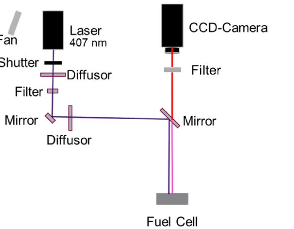
Oxygen sensitive dye solution was sprayed uniformly onto the GDL surface at the cathode flow channel to form a dye film with a thickness of approximately 2 µm [18, 19]. Figure 2-4 shows the optical setting of the visualization system. A diode laser was used for a bundled light with a wavelength of 407 nm. This blue light was diffused, guided by mirrors, and irradiated onto the dye film on the GDL in the fuel cell. The emission from the dye film inside the fuel cell was filtered (> 610 nm) and reached the charge coupled device (CCD) camera. All images were captured in a dark room.
21
Fig. 2-1 Schematic illustration of the fuel cell. (a): cover of the cathode heater, (b): cathode heater, (c): transpatent SiO2 endplate, (d): transparent PFA-film, (e): gasket,
(f): GDL, (g): channel plate, (h): endplate, (i): current collector, (j): catalyst coated membrane (CCM), (k): GDL with dye on the surface.
22
Fig. 2-3 Jablonski diagram of PtTFPP.
Fig. 2-2 Oxygen sensitive dye for visualizing p(O2) on the GDL surface at the cathode. (a):
Structure of PtTFPP as p(O2) senser. (b): The absorttion peaks and emission peak of PtTFPP.
23
Fig. 2-4 Schematic drawing of the visualization system with a diode laser, diffusors, mirrors, a fuel cell, filters, and a CCD-camera.
24
2.2.2 Calibration curves for oxygen partial pressure (p(O2))
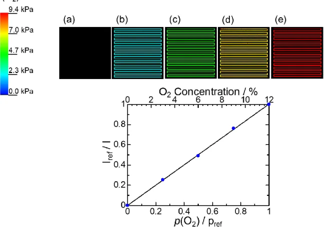
The calibration curve was assigned at each pixel of the CCD camera (250,000 pixels) before the cell operation [20, 21]. For the calibration, mixed gases of air, nitrogen, and water vapor with different p(O2) were introduced to the anode and cathode. A similar
method of diluting air for studying the oxygen starvation was previously reported [13, 22]. The cell temperature and relative humidity (RH) were set to 80 oC and 42%,
respectively. The oxygen concentrations were tuned at Φ(O2) = 10, 5, and 3%. The gas
flow rate at the anode and cathode sides was set to 100 mL min-1 under ambient
pressure. For each Φ(O2), a different calibration curve was prepared. The calibration
curve and images of each Φ(O2) are shown in Figs. 2-5, 2-6 and 2-7.
Fig. 2-5 Images at different p(O2) for calibration and averaged Stern-Volmer plots for
25
Fig. 2-6 Images at different p(O2) for calibration and averaged Stern-Volmer plots
for the visualization at Φ(O2) = 5%.
Fig. 2-7 Images at different p(O2) for calibration and averaged Stern-Volmer plots for
26
2.2.3 Power generation and cyclic voltammetry
The cell conditioning was executed at 80 oC and the above-mentioned relative
humidities with an air gas flow rate of 1000 mL min-1 on the cathode side and a hydrogen
gas flow rate of 249 mL min-1 on the anode side. The current density was set by a load
station (LN-1000A-G7, Keisoku Giken) to 0.8 A cm-2, held at least for 14 hours until the
voltage changes were below 2 mV h-1. The I-V curves at the different oxygen
concentration were obtained at 80 oC with an air flow rate of 200 mL min-1 on the cathode
and a hydrogen flow rate of 100 mL min-1 on the anode. The current density at each step
set by the load station was held for 10 minutes, and the voltage was monitored.
The cyclic voltammetry (CV) on the cathode was carried out with a potentiostat (PGSTAT302N, Metrohm Autolab B.V.). The hydrogen and nitrogen gas flow rates on the anode and the cathode, respectively, were set to 200 mL min-1, but the nitrogen gas
was stopped during the CV measurements. The cycles were repeated between 0.075 and 1.00 V (vs. the hydrogen electrode) with a scan rate of 20 mV s-1. Before the measurement,
four cleaning cycles were performed.
2.2.4 p(O2) visualization
During cell operation, the cell temperature was set at 80 oC under ambient pressure. The hydrogen flow rate at the anode was 100 mL min-1 humidified at 88% RH. The air flow
rate at the cathode was 200 mL min-1 at different p(O2) of 7.8 (Φ(O2) = 10%), 3.9 (Φ(O2)
= 5%), and 2.3 kPa (Φ(O2) = 3%), humidified at 42% RH. After changing the current
density, the cell conditions were kept for 10 min before the visualization. One image was obtained in 0.8 to 10 s depending on the emission intensity. With a total exposure time of at least 60 s, the images were accumulated and averaged. The emissions of the acquired
27
images were converted to p(O2) using the calibration curves.
2.3 Results and discussion
2.3.1 I-V performance depending on the oxygen concentration
Figure 2-8 shows the I-V curves at Φ(O2) = 10, 5, and 3%, where the stoichiometries of
hydrogen:oxygen were 1:0.39, 1:0.19, and 1:0.11, respectively. Below 0.6 V, the cell performance suddenly decreased at all Φ(O2). The voltage decreased rapidly at lower
Φ(O2), most significantly at Φ(O2) = 3%; at 0.054 A cm-2, the voltage abruptly dropped
to 0.28 V. The starvation of oxygen had large negative influences on the I-V performance. The electrochemical surface areas obtained by CV measurements were 69.9 and 67.6 m2
g-1 before and after the visualization, respectively, showing little change. Therefore, the
degradation of the catalysts was negligible.
Fig. 2-8 I-V curves during cell operation at Φ(O2) = 10, 5,and 3%. The lines are
28
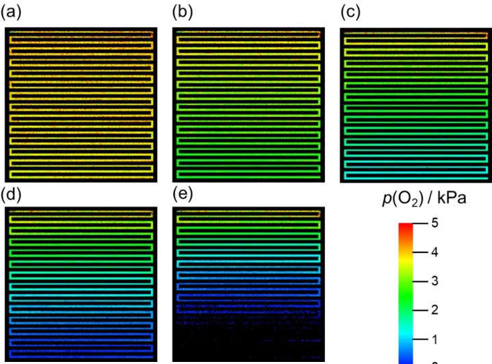
2.3.2 Visualization images of p(O2) distribution during power generation
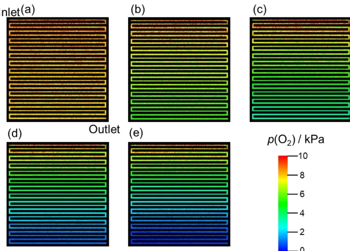
Figures 2-9, 2-10, and 2-11 show the p(O2) images obtained during cell operation at
Φ(O2) = 10, 5, and 3%, respectively. The top left corner in each image is of the gas inlet
of the single serpentine gas flow channel, and the bottom right corner of the gas outlet. The colors shown in the images represent p(O2) on the GDL surface and are defined with
the associated color bar. Figure 2-9(a) shows p(O2) at 0 A cm-2 (UO2 = 0%). The slight
change in color starting from the gas inlet at the top left (ca. 9 kPa) to the gas outlet at the bottom right of the cell was caused by the pressure loss [3, 10, 18] by ca. 1 kPa of p(O2),
corresponding to ca. 10 kPa of air inside the cell. Figure 2-9(b) shows the visualization image obtained at 0.06 A cm-2 and U
O2 = 30.5%. A decrease in p(O2) is clearly visible by
the change of color along the gas flow channel; the color along the gas flow channel changes from red-orange (ca. 9 kPa) near the gas inlet to yellow (ca. 7 kPa) near the middle of the cell, then to light green (ca. 5 kPa) near the gas outlet of the cell. Figure 2-9(c) shows the visualization images at 0.12 A cm-2 (U
O2 = 60.9%). Compared to the image
in Fig. 2-9(b), p(O2) in Fig. 2-9(c) decreased at an earlier stage along the gas flow channel.
Figures 2-9(d) and 2-9(e) show the visualization image at 0.18 A cm-2 (U
O2 = 91.4%) and
0.19 A cm-2 (U
O2 = 96.5%), respectively. The decrease in p(O2) was the largest along the
flow channel length at 0.19 A cm-2,and p(O
2) became ca. 0.3 kPa at the outlet. Figures
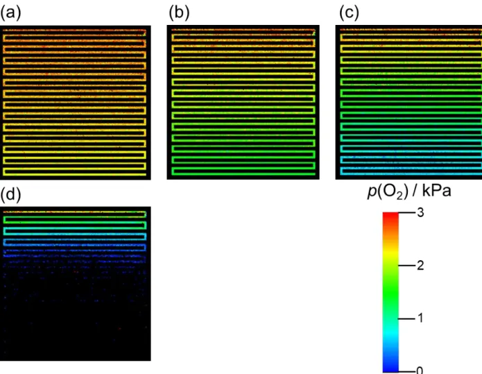
from 2-10(a) to 2-10(e) show the images obtained at 0 (UO2 = 0%), 0.03 (UO2 = 30.5%),
0.06 (UO2 = 60.9%), 0.09 (UO2 = 91.4%), and 0.095 A cm-2 (UO2 = 96.5%), respectively,
at Φ(O2) = 5%. The UO2 values were set to the same as those for Φ(O2) = 10%. The
pressure loss at 0 A cm-2 was ca. 0.6 kPa of p(O
2) or ca. 10 kPa of air. Compared with Fig.
2-9, it is understood that as the UO2 increased, the consumption of O2 proceeded closer to
the inlet. Figure 2-10(e) shows the image obtained at 0.095 A cm-2 or U
29
Theoretically, there should be oxygen remaining inside the gas flow channel at the outlet with ca. 0.2 kPa, but the color in the last one third along the gas flow channel changed to black, which indicated p(O2) = 0 kPa on the GDL surface. The distribution of p(O2) on
the GDL at Φ(O2) = 10% was very different from that at Φ(O2) = 5% with the same UO2
of 96.5%, where p(O2) at the outlet was ca. 0.3 kPa (Fig. 2-9(e)). Therefore, nearly the
last third of the CL did not generate power at Φ(O2) = 5%, which is later discussed. As
previously demonstrated by the simultaneous visualization of p(O2) on the GDL surface
and on the upper gas flow channel wall [22], there is a possibility that oxygen still remained in the gas flow channel. Figure 2-11 shows the images obtained at 0 (UO2 = 0%)
(a), 0.018 (UO2 = 30.5%) (b), 0.036 (UO2 = 60.9%) (c), and 0.054 A cm-2 (UO2 = 91.4%)
(d), respectively, at Φ(O2) = 3%. The pressure loss was ca. 0.3 kPa of p(O2), or ca. 10 kPa
of air, as well as at Φ(O2) =10 and 5%. Figure 2-11(d) (0.054 A cm-2, UO2 = 91.4%) is
striking; the latter two thirds of the image are in black, or p(O2) = 0 kPa, on the GDL
30
Fig. 2-9 Images of p(O2) on the GDL surface at the cathode at Φ(O2) = 10% during cell
operation (T = 80 oC, air flow rate = 200 mL min-1, hydrogen flow rate = 100 mL min -1, ambient pressure) at 0 (U
O2 = 0%) (a), 0.06 (UO2 = 30.5%) (b), 0.12 (UO2 = 60.9%)
(c), 0.18 (UO2 = 91.4%) (d), and 0.19 A cm-2 (UO2 = 96.5%) (e). Associated color bar
31
Fig. 2-10 Images of p(O2) on the GDL surface at the cathode at Φ(O2) = 5% during cell
operation (T = 80 oC, air flow rate = 200 mL min-1, hydrogen flow rate = 100 mL min-1,
ambient pressure) at 0 (UO2 = 0%) (a), 0.03 (UO2 = 30.5%) (b), 0.06 (UO2 = 60.9%) (c),
0.09 (UO2 = 91.4%) (d), and 0.095 A cm-2 (UO2 = 96.5%) (e). Associated color bar
32
Fig. 2-11 Images of p(O2) on the GDL surface at the cathode at Φ(O2) = 3% during
cell operation (T = 80 oC, air flow rate = 200 mL min-1, hydrogen flow rate = 100 mL
min-1, ambient pressure) at 0 (U
O2 = 0%) (a), 0.018 (UO2 = 30.5%) (b), 0.036 (UO2 =
60.9%) (c), 0.054 A cm-2 (U
33
Figure 2-12 shows the continuous line plots of p(O2) on the GDL surface in the middle
of the flow channel with a width of a pixel (ca. 120 mm) along the flow channel length from the inlet to the outlet at Φ(O2) = 10 (a), 5 (b), and 3% (c) at different current densities.
The black line represents UO2 = 0%, the red line 30.5%, the orange line 60.9%, the green
line 91.4% and the blue line 96.5%. p(O2) values showed 1 to 2 kPa scattering due to the
geometrical effects of the flow channel and the GDL [18, 24]. It is noticeable that the trends of these line plots of p(O2) under UO2 = 0, 30.5, and 60.9% represented by black,
red and orange lines, respectively, are similar at different Φ(O2) values. However, these
trends started to differ at UO2 ≥ 91.4%. The decrease of p(O2) along the gas flow channel
34
Fig. 2-12 p(O2) plotted along the flow channel length. The black lines represent UO2 =
0%, the red lines UO2 = 30.5%, the orange lines UO2 = 60.9%, the green lines UO2 =
35
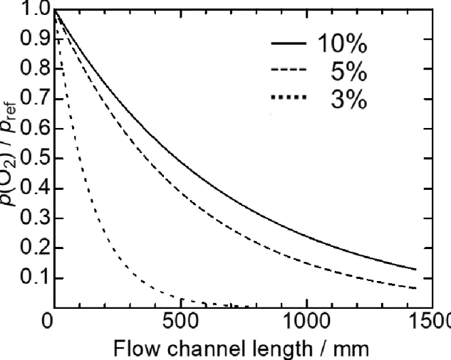
Figure 2-13 shows the trendlines of the line plots derived from Fig. 2-10. These trendlines were normalized by the averaged values of the first 100 data points of each step along the flow channel length. The large decrease of p(O2) is clearly seen at the early
stage along the flow channel length at lower Φ(O2).
Fig. 2-13 Normalized trendlines of line plots derived from Fig. 2-9 at Φ(O2) = 10, 5,
36
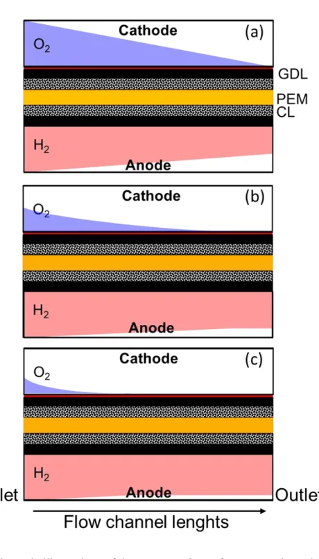
Figure 2-14 schematically illustrates the oxygen and hydrogen partial pressures along the flow channel lengths. At low Φ(O2) (≤ 5%), oxygen became to be consumed at the
earlier stage along the flow channel length, and at high UO2 (≥ 91.4%), p(O2) near the
outlet became 0 kPa on the GDL surface (Figs. 2-9 and 2-10). To understand p(O2) = 0
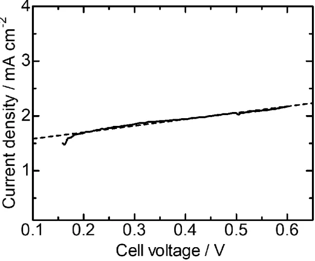
kPa on the GDL surface near the outlet, the linear sweep voltammetry (LSV) was conducted (Fig. 2-15) for determining the effect of the cross leakage of hydrogen from the anode through the membrane to the cathode. The temperature and humidity were the same as those during cell operation. For the LSV, nitrogen was supplied to the cathode, and hydrogen to the anode. The flow rates of both gases were set at 200 mL min-1. The
amount of the hydrogen cross leak was measured as 0.028 mL min-1 cm2, similar to the
value previously reported (< 0.02 mL min-1 cm2) [25]. The oxygen consumption caused
by this hydrogen cross leakage would be only 0.07-0.7% of that existed in the diluted air, therefore, the influence of the hydrogen cross leakage on the oxygen consumption at the cathode was expected to be very small. In addition, the amount of oxygen cross leakage is significantly lower, 1/10 to 1/100 of that of hydrogen. The gas cross leakage could not explain p(O2) = 0 kPa on the GDL surface.
37
Fig. 2-14 Schematic illustrations of the concentrations of oxygen at the cathode and hydrogen at the anode along the channel lengths. Φ(O2) = 10 (a), 5 (b), and 3% (c).
38
Fig. 2-15 Linar sweep voltanmetory. The cell temperature was 80 oC, and the RHs at
39
Since the area for the power generation shifted near to the inlet, the electrochemical potential at the MEA near the outlet might be lowered. In an MEA using a gas diffusion electrode, hydrogen evolution and the oxidation current of the generated hydrogen gas are often observed at potentials lower than ca. 0.1 V (vs. hydrogen electrode) [9]. Therefore, a possibility is that the potential decreased to 0.1 V or less at the MEA near the outlet, and the hydrogen evolution occurred at the cathode, which chemically/electrochemically consumed oxygen near the outlet [9]. Previously, the zero current regions were not observed during oxygen starvation in a segmented cell [9]. Considering the hydrogen evolution at the cathode, it is reasonably understood that the regions exist where the current density is not 0 A cm-2 [26] but p(O
2) = 0 kPa (this study).
Based on the previous results discussing the differences of p(O2) on the GDL and in
the gas flow channel [27], a possibility of the coexistence of oxygen and hydrogen in the flow channel at the cathode is not negligible, which might cause not only a performance drop but also an operational instability and a danger for the cell damage presumably triggered by the unexpected chemical reaction, or local combustion, directly with hydrogen and oxygen. Actually, in a fuel cell stack, Mousa et al. detected a hydrogen concentration of 6.3% at the cathode outlet at Φ(O2) = 5% and that of 9.4% at Φ(O2) =
3% [13]. They explained the existence of those large amounts of hydrogen at the cathode outlet by proposing a mechanism of hydrogen pumping through the membrane to the cathode [13]. In our case in a single cell, the hydrogen pumping could not occur because of no energy supply for the pumping.
The visualized images of p(O2) inside a single cell (Figs. 2-9 ~ 2-11) in this study might
be depicting the situation that could occur prior to the hydrogen pumping inside fuel cell stacks during oxygen starvation. The consumption of oxygen at the cathode significantly
40
reduced the performance of a single cell (Fig. 2-13). In the areas of an MEA not exposed to oxygen, the CL is expected to be susceptible to degradation. For example, Yamashita et al. reported the effect of oxygen starvation on the degradation of Pt catalysts supported on carbon at the cathode upon hydrogen start-up [28]. The oxidation reaction of carbon by water proceeded by local electrochemical cells arising due to a limited access of hydrogen needed for the reduction of Pt oxides. Within a fuel cell stack, the area in which oxygen starvation occurs in a single cell might prohibit the current flow at the identical areas of the other cells. Therefore, there is a possibility that the oxygen starvation in a single cell could drastically lower the performance of the entire stack. The oxygen starvation could be a larger problem in stacks operated at high current densities.
41
2.4 Conclusion
The p(O2) distribution at low Φ(O2) on the GDL surface at the cathode inside a PEMFC
was visualized by a nondestructive real-time/space monitoring system. It was shown that
p(O2) decreased along the flow channel length. The decrease of p(O2) along the flow
channel length at UO2 of 0, 30.5, and 60.9% were similar at Φ(O2) = 10, 5 and 3% but
started to differ at UO2 ≥91.4%. The low Φ(O2) and high UO2 lead to a significant decrease
of p(O2) near the outlet. At very low Φ(O2) and very high UO2, there was no oxygen
present on the GDL surface near the gas outlet possibly because of a generation of hydrogen at the cathode due to the local low voltage. Accordingly, at lower Φ(O2) and
high UO2, the starvation of oxygen lowered the cell performance of a single cell.
Experimentally, the hydrogen evolution at the cathode prior to the hydrogen pumping from the anode was evidenced by showing areas on the GDL where p(O2) = 0 kPa. The
effects should be more pronouncedly on the performance, stability, and durability, as well as safety, of fuel cell stacks.
42
References
[1] R. Borup, J. Meyers, B. Pivovar, Y. S. Kim, R. Mukundan, N. Garland, D. Myers, M. Wilson, F. Garzon, D. Wood, P. Zelenay, K. More, K. Stroh, T. Zawodzinski, J. Boncella, J. E. McGrath, M. Inaba, K. Miyatake, M. Hori, K. Ota, Z. Ogumi, S. Miyata, A. Nishikata, Z. Siroma, Y. Uchimoto, K. Yasuda, K. I. Kimijima, N. Iwashita, Chem. Rev. 107 (2007) 3904–3951.
[2] J. C. Kurnia, A.P. Sasmito, T. Shamim, Appl. Energy 252 (2019) 113416. [3] Z. Y. Liu, B. K. Brady, R. N. Carter, B. Litteer, M. Budinski, J. K. Hyun, D. A.
Muller, J. Electrochem. Soc. 155 (2008) B979–B984.
[4] N. Yousfi-Steiner, P. Moçotéguy, D. Candusso, D. Hissel, J. Power Sources 194 (2009) 130–145.
[5] S. B. Beale, U. Reimer, D. Froning, H. Jasak, M. Andersson, J. G. Pharoah, W. Lehnert, J. Electrochem. Energy Convers. Storage 15 (2018) 1–7.
[6] A. Manokaran, S. Pushpavanam, P. Sridhar, J. Appl. Electrochem. (2015) 353– 363.
[7] K. Mitsuda, H. Nishiguchi, Electrochemistry 78 (2010) 757–763.
[8] M. Gerard, J. P. Poirot-Crouvezier, D. Hissel, A. M. Marie-Cecile Pera, B. Bador, J Fuel Cell Sci Technol 7 (2010) 361–369.
[9] Z. Liu, L. Yang, Z. Mao, W. Zhuge, Y. Zhang, L. Wang, J. Power Sources 157 (2006) 166–176.
[10] K. Takanohashi, T. Suga, M. Uchida, T. Ueda, Y. Nagumo, J. Inukai, H. Nishide, M. Watanabe, J. Power Sources 343 (2017) 135–141.
[11] K. Takada, Y. Ishigami, J. Inukai, Y. Nagumo, H. Takano, H. Nishide, M. Watanabe, J. Power Sources 196 (2011) 2635–2639.
43
[12] K. Nagase, T. Suga, Y. Nagumo, M. Uchida, J. Inukai, H. Nishide, M. Watanabe, J. Power Sources 273 (2015) 873–877.
[13] G. Mousa, J. DeVaal, F. Golnaraghi, Int. J. Hydrogen Energy 39 (2014) 21154– 21164.
[14] H. Chena, X. Zhaoa, T. Zhanga, P. Peib, Energy Convers. Manag. 182 (2019) 282–298.
[15] K. Asai, Y. Amao, Y. Iijima, I, Okura, H. Nishide, J. Thermophys. Heat Transfer 16 (2002) 109–115.
[16] T. Masuda, E. Isobe, T. Higashimura, J. Am. Chem. Soc. 105 (1983) 7473–7474. [17] J. Inukai, K. Miyatake, K. Takada, M. Watanabe, T. Hyakutake, H. Nishide, Y. Nagumo, M. Watanabe, M. Aoki, H. Tanano, Angew. Chem. Int. Ed. 47 (2008) 2792–2795.
[18] T. Hyakutake, H. Taguchi, J. Kato, H. Nishide, M. Watanabe, Macromol. Chem. Phys. 210 (2009) 1230–1234.
[19] T. Hyakutake, Y. Ishigami, J. Kato, J. Inukai, K. Miyatake, H. Nishide, M. Watanabe, Macromol. Che. Phys. 212 (2011) 42–47.
[20] J. Inukai, K. Miyatake, Y. Ishigami, M. Watanabe, T. Hyakutake, H. Nishide, Y. Nagumo, M. Watanabe, A. Tanaka, Chem. Commun. (2008) 1750–1752.
[21] Y. Ishigami, K. Takada, H. Yano, J. Inukai, M. Uchida, Y. Nagumo, T. Hyakutake, H. Nishide, M. Watanabe, J. Power Sources 196 (2011) 3003–3008.
[22] A. M. Niroumand, H. Homayouni, J. DeVaal, F. Golnaraghi, E. Kjeang, J. Power Sources 322 (2016) 147–154.
[23] K. Nagase, H. Motegi, M. Yoneda, Y. Nagumo, T. Suga, M. Uchida, J. Inukai, H. Nishide, M. Watanabe, ChemElectroChem. 2 (2015) 1495–1501.
44
[24] K. Takanohashi, M. Uchida, A. Iiyama, J. Inukai, J. Surf. Fin. Soc. Jpn. 68 (2017) 338–343.
[25] "DupontTM Nafion® NR211 and NR212 Ion Exchange Materials",
https://www.fuelcellstore.com/spec-sheets/chemours-nafion-211-212-spec-sheet.pdf (October 20, 2020).
[26] R. N. Carter, S. S. Kocha, F. Wagner, M. Fay, H. A. Gasteiger, ECS Trans. 11 (2007) 403–410.
[27] Y. Ishigami, W. Waskitoaji, M. Yoneda, K. Takada, T. Hyakutake, T. Suga, M. Uchida, Y. Nagumo, J. Inukai, H. Nishide, M. Watanabe, J. Power Sources 269 (2014) 556–564.
[28] Y. Yamashita, S. Itami, J. Takano, K. Kakinuma, H. Uchida, M. Watanabe, A. Iiyama, M. Uchida, J. Electrochem. Soc. 164 (2017) F181–F187.
45
Chapter 3
Oscillation mechanism based on operando p(O
2) measurement using
optical probes
3.1 Introduction
Under certain conditions, the cell voltage and the current density become unstable and even fluctuated because of the instability of the reactions inside PEMFCs. Since the excess liquid water in a cell is one of the main sources of instability, the water management during power generation has been extensively studied [1, 2]. The water generated by the power generation is continuously removed outside the fuel cell through the GDLs. However, when the water generation is too large, the flooding is inevitable. Therefore, a proper water management is of paramount importance for PEMFCs. Materials must be developed, and the operating conditions and the cell configurations must be optimized. Barbir et al. investigated unexpected increases in pressure and cell resistance of a PEMFC stack during power generation [3]. They pointed out that the increase in pressure could be indicative of the increased liquid water in the stack, while the increase in cell resistance is of a membrane dry-out. Hirakata et al. investigated the effect of pore size of GDL on the periodic instability of the cell voltage accompanied by the synchronized change in gas pressure, which were conclude to be caused by the water droplets blocking/releasing the cathode flow channel [4].
Recently, the oscillation phenomena during the power generation have been reported in running PEMFCs. Sanchez and coworkers reported an oscillatory fluctuation when the cathode was dry and the anode was wet at a nominal humidity of 152% with the cell temperature of 70 oC [5]. The current density first decreased slowly from 650 to 610 mA cm-2 within 1000 s at a constant cell voltage of 500 mV. Subsequently, a fluctuation in
46
current density started, followed by a continuous oscillation between 600 and 60 mA cm
-2 accompanied by a gradual decrease in average current density resulting in the decrease
in cell performance. During the oscillation, the transition from the lowest current to the highest current took place in 20 s, and the transition from the highest to the lowest slightly longer than 20 s. The change of the coefficient of the electro-osmotic drag accompanied by that of the liquid-vapor permeation at the interface of the membrane was suggested as a major feedback mechanism for the oscillatory behavior [5,6]. The change in the properties at the membrane interface was visualized by current-sensing atomic force microscopy showing the oscillatory behaviors after the activation of the membrane [5]. The fluctuations were related to the water shortage at the anode, too. A combination of the limited water available at the anode, the electroosmotic drag transporting water from the anode to the cathode, and the insufficient water back diffusion from the cathode to the anode was proposed to cause the anode to dehydrate. The cell ohmic resistance decreased and the performance recovered by the anode re-humidification [7] Atkins et al. found periodic oscillations in current and cell resistance at a fixed cell potential of 500 mV [8]. From the initial conditions using sparger bottles for the feed-stream humidification (cell temperature = 100 ºC, sparger temperatures at the anode/cathode = 115 ºC /110 ºC), the temperatures of the sparger bottles were lowered to 80 oC. Large fluctuations and a significant decrease of the current density, approximately 0.5 A cm-2, were observed. The
oscillation period of current was several hundreds of seconds and become larger when the sparger temperature was kept at 80 ºC. The ohmic resistance also oscillated between 50 and 250 mΩ.
I found a new oscillation phenomenon during the power generation at 0.6 A cm-2 using
47
cathode inlet and outlet was 0 kPa during the oscillation. This phenomenon is very different from the cell voltage fluctuation previously reported to be synchronized with the differential pressure caused by the plugging of flow channels [4]. A different mechanism should have caused this new oscillation phenomenon without the excess liquid water in the gas flow channel. The amplitude and period of this newly-found oscillation were approximately 20 mV and 2 s, respectively, whereas the oscillation or fluctuation of the cell voltage previously reported at the dried cathode showed a period significantly longer than ours, about tens of seconds to hours [5–8]. The oscillation amplitudes of the current-density at constant voltages in previous studies were large, too: 0.05 - 0.55 [5,6], 0.5 - 1.1 [7], and0.55 - 0.83 A cm-2 [8].
In order to elucidate the mechanism of this new oscillation phenomenon, p(O2) inside
the GDLs during the power generation [9–17] was focused on, because p(O2) is directly
related to the fuel cell overvoltage according to Nernst equation as described in Chapter 2.
William et al. developed an operando measurement system to obtain the oxygen concentration [18] using a commercially-available micro oxygen-concentration sensor 25 m in diameter inserted into the GDL at the cathode of an operating PEMFC. The oxygen concentration was measured at different current densities and RHs. By using an X-ray computed tomography (CT) system, the GDL structure was also analyzed to be related to the oxygen transport resistance. In their system, as an current interrupt method for measuring the ohmic resistance andthe current of PEMFC was interrupted [19]. When the current was interrupted, the oxygen concentration returned to the channel level in milliseconds, while the changes in the behavior of the sensor due to RH and temperature occurred over seconds [18]. Therefore, for a monitor of p(O2), at least 5 s was needed. In
48
addition, the measurements at multiple locations was not easy due to the size and strength of the oxygen sensor made with glass capillaries [18]. The group of the University of Yamanashi has developed a 2-dimensinal visualization system of p(O2) on the GDL
surface and the flow-channel walls inside running PEMFCs using an oxygen-sensitive dye film [9–17]. To monitor p(O2) inside a GDL, a new apparatus using 5 optical fibers
with diameter of 50 µm was developed. The probes can be precisely located with a spatial resolution of 1 m in depth, and p(O2) can be simultaneously measured at 5 points both
under the flow channel and under the ribs. The time resolution was 100 ms. With using this operando monitoring system, the voltage oscillation was found to be synchronized with p(O2) oscillation at all the locations inside the GDL.
3.2 Instrument
3.2.1 Oxygen-sensitive dye film
As described in Chapter 2, PtTFPP mixed with polyTMSP and toluene was used as an oxygen-sensitive dye to spray onto the GDL surface at the cathode flow channel. The PtTFPP concentration of the dye solution was adjusted to 25 wt%. PtTFPP has absorption peaks at 400 (blue light) and 530 nm (green light), and an emission peak of at 650 nm (red light). In this study, green light was used for the detection of p(O2) because of the
excitation of Si of an optical fiber by blue light.
3.2.2 Optical fiber
Single-mode optical fibers with a clad diameter of 125 μm and a core diameter of 10 μm were immersed in HF solution (pH = 2.9) and etched until the diameter of approximately 50 μm was obtained. Subsequently, the top of the optical fiber was trimmed flat
49
perpendicular to the fiber axis. On the apex of a fiber, an oxygen-sensitive dye film was coated with a thickness of 2 µm.
The emission intensity as a function of the temperature was negligibly small, with the change in the emission of -0.5% K-1 [9]. The influence of the humidity on the oxygen
partial pressure in air was negligibly small, too [9]. When the dye film at the apex of a probe was wet with liquid droplets, the emission intensity much increased [10,14]. Under the conditions for the power generation in this study, the apex of the probe was never wet, and the intensity of the emission was steadily monitored.
3.2.3 Oxygen monitoring system
Figure 3-1(a) shows a schematic representation of the p(O2) monitoring system. In the
cathode side of a GDL, 5 holes were created down to the CL both under the flow channels and the ribs. The optical probes were inserted directly into a PEMFC through the holes. The probe position was controlled by a micrometer. The effect of inserting the probe into the manufactured hole to mass fraction of oxygen was simulated. Figures 3-2(a) ~ (c) show an X-ray CT image of a GDL, a 3-dimensional numerical simulation of mass fraction of oxygen inside the GDL, and a cross-sectional numerical simulation of mass fraction of oxygen inside the GDL without a hole, respectively. Figures 3-2(d) ~ (f) show an X-ray CT image of a GDL with a hole (90 µm in diameter) and an optical probe (50 µm in diameter) inserted, a 3-dimensional numerical simulation of the mass fraction of oxygen inside the GDL, and a cross-sectional numerical simulation of the mass fraction of oxygen inside the GDL with a hole and an optical probe, respectively. The oxygen concentrations at the surfaces of the GDL at the CL side were set at the values expected at the current density of 1.0 A cm-2. The colors shown in the images represent the mass
50
fraction of oxygen and are defined with the associated color bar. The oxygen mass fraction was calculated inside the GDL based simply on the diffusion and the difference was less than 1% with/without a hole and a probe. Figures 3-3(a) and (b) are calculated oxygen mass fraction at the apex of the probe at different depths at 0.2 and 1.0 A cm-2, respectively.
With and without the virtual probes, the differences were approximately 1%.
For measuring the distance between the probe apex and the CL, a super luminescent diode light with a wavelength of 830 nm was introduced to the probe to obtain an interference light from the CL and the probe apex (Fig. 3-1(b)). The spectrum of reflection light out from the optical probe was Fourier-transformed to measure the distance with an error of 1 µm.
51
Fig. 3-1 (a): Schematic representation of p(O2) measurement inside GDL. (b): Interference
between the lights from the probe tip and the surface of catalyst layer Fourier-transformed to determine distance from catalyst layer.
52
Figure 3-2 (a): X-ray CT image of GDL without a hole. (b): 3-dimensional numerical simulation of mass fraction of oxygen inside GDL without a hole. (c): Cross-sectional numerical simulation of mass fraction of oxygen inside GDL without a hole. (d): X-ray CT image of GDL with a hole (90 µm in diameter) and an optical probe (50 µm in diameter). (e): 3-dimensional numerical simulation of mass fraction of oxygen inside GDL with a hole and an optical probe. (f): Cross-sectional numerical simulation of mass fraction of oxygen inside GDL with a hole and an optical probe. The data are provided from Mizuho Information & Research Institute.
53
Figure 3-3 Calculated oxygen mass fraction at probe apex at different probe positions at 0.2 (a) and 1.0 A cm-2 (b). The data are
54
3.2.4 Cell for the oxygen monitoring
Figure 3-4(a) shows the structure of a cell with 10 straight flow channels for p(O2)
monitoring. At the cathode side of a stainless endplate, a window was created for the insertion of the optical probes. An acrylic insulator plate with 5 holes was inserted between the endplate and the current collector for the probe positioning. The cathode and the anode gases were supplied as parallel flows. The channel length was 30 mm. The ribs and the cathode and the anode were at the overlapping positions. The active catalyst area was 20 mm×20 mm. Figure 3-4(b) shows the positions of the holes created through the GDLs under the central rib, located at 2.5, 10.0, and 17.5 mm from the edge of the GDL and 5.0 and 15.0 mm under the flow channels from the GDL edge.
Fig.3-4 (a): Cell used for operando
p(O2) measurement. (b): Positions of
holes at GDL, or locations for p(O2)
55
3.2.5 Optical diagrams
As shown in Fig. 3-5(a), a 532 nm diode laser light was divided into 5 by beam splitters to 2 μW. Each light was irradiated onto the oxygen-sensitive dye film at the apex of the probes. The excitation light and the 650 nm emission were separated by a dichroic mirror, and the emission was detected by a CCD camera with a filter for the reflective excitation light placed in front of the camera. An optical diagram of the probe positioning is shown in Fig. 3-5(b). The probes were positioned as described in Section 3.2.3.
Figure 3-5 Schematic diagrams of p(O2) (a) and distance (b) measurement systems.
Optical components are allotted as 1: Diode laser (532 nm), 2: Quarter-wave plate, 3: Extinction filter, 4: Mirror, 5: Shutter, 6: Beam splitter, 7: Dichroic mirror, 8: Optical fiber, 9: Fuel cell, 10: Objective lens, 11: Reflection exciting light filter, 12: CCD camera, 13: SLD (830 nm), 14: Diffraction grating, 15: CCD camera.