アクセサリ
ACCESSORIES
. Auflage 06/17 · Gedruckt in Deutschland · Gedruckt auf 100 % chlorfrei gebleichtem Papier
· 070617 JP/EN · 技術 デ ー タ は 予告無 く 変更 す る こ と が あ り ま す 。.
22
技術データは予告無く変更することがあります。的確にお応えするためには
F O R G O O D C O M M U N I C AT I O N
迅速なサービスと対応を提供させ
て頂くため、ご注文もしくはお問
い合わせ時に貴社お客様番号をお
知らせ下さい。
To ensure fast service and smooth
processing of purchase orders,
please include your HAIMER
cus-tomer number with all orders and
inquiries.
HAIMER社用 貴社お客様番号
Your HAIMER customer number:
お客様番号
Customer-No.
電話
/
Phone
+49-82 57-99 88-0
Fax
+49-82 57-18 50
[email protected]
HPアドレス
www.haimer.com
ハイマージャパン株式会社
大阪市北区松ヶ枝町1-39 東天満エンビイビル1F
電話:06-4792-7980 · Fax:06-4792-7871
[email protected] · www.haimer.jp
目次/
C O N T E N T S
アクセサリ
Accessories
製品名/
Article
ページ/
Page
シュリンクフィット エクステンション
Shrinking Extensions
4
リダクションスリーブ
Reduction Sleeves
8
Cool Jet 9
Cool Flash 10
ER コレット
Collets ER
12
パワーコレットチャック用コレット
Collets for HAIMER Power Collet Chuck
16
トルクマスター・トルクレンチ
Torque Master Torque Wrench
18
ツールクランプ
Tool Asembly device Tool Clamp
19
コレットホルダー用ロックナット
Locknuts for collet chucks
20
レンチ
Wrenches
21
ハイプレシジョンチャック(HG)用 コレット・内径
クリーナー
HG Collets and HG Cone Wiper
22
プルスタッド
Pull Studs
23
サイドカッター アーバー
Sawblade Holders
26
HGミニ エクステンション
HG Mini Extensions
27
バランシングリング
Balancing Index Rings
28
バランシングスクリュー
Set of Balancing Screws
29
シュリンクフィットチャック 内径用ブラシ/クーラ
ントチューブ
Shrink Fit Brush, Coolant tube
30
スピンドル用クリーナー
Cone Wiper
31
バックアップスクリュー
Back up Screws
32
シュリンクフィットチャック用スプリング
Tension Spring for shrink fit chuck
35
クランピングスクリュー
Clamping Screws
36
フェイスミル/コンビネーションシェル用 アクセサリ
Accessories Face Mill, Combination Shell
37
クイックチェンジインサート タイプFH
4
L A Ø D3 A 0.003 Ø D1 Ø D2 A 4.5° 技術データは予告無く変更することがあります。シュリンクフィット エクステンション
S H R I N K F I T E X T E N S I O N S
注文番号 L A寸法 外径 Ø シャンク公差 把握径 Ø Ø クーリングボ クーリングアダプターOrder No. Length A Outer Ø Shank tolerance Clamping Ø ディー
[mm] [mm] D3 [mm] D1 [mm] D2 [mm] Cooling body Adapter 78.160.06 28 160 16 h6 6 10 Ø 14–16 80.105.14.1.1 78.200.06 28 160 20 h6 6 14 Ø 14–16 80.105.14.1.2 78.200.08 34 160 20 h6 8 14 Ø 14–16 80.105.14.1.2 78.250.08 34 160 25 h6 8 19 Ø 6–8 — 78.250.10 42 160 25 h6 10 20 Ø 6–8 — 78.250.12 47 160 25 h6 12 20 Ø 6–8 — 78.250.14 47 160 25 h6 14 20 Ø 6–8 — 78.250.16 50 160 25 h6 16 22 Ø 6–8 — 78.320.10 42 160 32 h6 10 24 Ø 10–12 — 78.320.12 47 160 32 h6 12 24 Ø 10–12 — 78.320.14 47 160 32 h6 14 27 Ø 14–16 — 78.320.16 50 160 32 h6 16 27 Ø 14–16 — 78.320.18 50 160 32 h6 18 27 Ø 14–16 — 78.320.20 52 160 32 h6 20 27 Ø 14–16 — テレスコープ Telescope 仕様: –バックアップスクリューは含まず –外部冷却用のスリットタイプのノズル付き –自由に長さ調整可能(テレスコープ参照) Version: – Without set screw
– With slits along the clamping bore for proper clamping and coolant around the cutting tool
– Variable length setting (telescope)
注文番号 L A寸法 外径 Ø シャンク公差 把握径 Ø Ø クーリングボ クーリングアダプター
Order No. Length A Outer Ø Shank tolerance Clamping Ø ディー
[mm] [mm] D3 [mm] D1 [mm] D2 [mm] Cooling body Adapter 78.120.03.2 — 160 12 h6 3 8 Ø 14–16 80.105.14.1.1 78.120.04.2 — 160 12 h6 4 8 Ø 14–16 80.105.14.1.1 78.160.03.2 — 160 16 h6 3 10 Ø 14–16 80.105.14.1.1 78.160.04.2 — 160 16 h6 4 10 Ø 14–16 80.105.14.1.1 78.160.05.2 — 160 16 h6 5 10 Ø 14–16 80.105.14.1.1 78.200.05.2 — 160 20 h6 5 14 Ø 14–16 80.105.14.1.2 深穴加工時や長いホルダー長が必要な場合の問題を一気 に解決します –最高レベルの振れ精度 –制限無しに継ぎ足し可能 –何度も取り外し可能、組み合わせは自由 –特殊ホルダーが不要、経済的で経費削減を実現 –超硬及びハイス工具使用可能 –クーリングアダプターは含まず(別途ご注文下さい)
The universal solution for your machining issues
– Highest runout accuracy
– Optimum and almost unlimited extensions likely – Versatile to use and always re-usable
– The most economic way for special machining requi-rements
– For carbide steel and HSS shanks – Delivery without cooling adapter
仕様:
–バックアップスクリュー付き(調整幅 10mm)
Version:
シュリンクフィット エクステンション
S H R I N K F I T E X T E N S I O N S
注文番号 L A寸法 外径 Ø シャンク公差 把握径 Ø Ø クーリングボ クーリングアダプター
Order No. Length A Outer Ø Shank tolerance Clamping Ø ディー
[mm] [mm] D3 [mm] D1 [mm] D2 [mm] Cooling body Adapter 78.120.03.1 — 160 12 h4 3 8 Ø 14–16 80.105.14.1.1 78.120.04.1 — 160 12 h4 4 8 Ø 14–16 80.105.14.1.1 78.160.03.1 — 160 16 h4 3 10 Ø 14–16 80.105.14.1.1 78.160.04.1 — 160 16 h4 4 10 Ø 14–16 80.105.14.1.1 78.160.05.1 — 160 16 h4 5 10 Ø 14–16 80.105.14.1.1 78.160.06.1 — 160 16 h6 6 10 Ø 14–16 80.105.14.1.1 78.200.05.1 — 160 20 h4 5 14 Ø 14–16 80.105.14.1.2 78.200.06.1 — 160 20 h6 6 14 Ø 14–16 80.105.14.1.2 78.200.08.1 — 160 20 h6 8 14 Ø 14–16 80.105.14.1.2 78.250.08.1 — 160 25 h6 8 19 Ø 6–8 — 78.250.10.1 — 160 25 h6 10 20 Ø 6–8 — 78.250.12.1 — 160 25 h6 12 20 Ø 6–8 — 78.250.14.1 — 160 25 h6 14 20 Ø 6–8 — 78.250.16.1 — 160 25 h6 16 22 Ø 6–8 — 78.320.10.1 — 160 32 h6 10 24 Ø 10–12 — 78.320.12.1 — 160 32 h6 12 24 Ø 10–12 — 78.320.14.1 — 160 32 h6 14 27 Ø 14–16 — 78.320.16.1 — 160 32 h6 16 27 Ø 14–16 — 78.320.18.1 — 160 32 h6 18 27 Ø 14–16 — 78.320.20.1 — 160 32 h6 20 27 Ø 14–16 — テレスコープ Telescope 仕様: 300 mm lang –バックアップスクリューは含まず –自由に長さ調整可能(テレスコープ参照)
Version: Extension length 300 mm – Without set screw
– Variable length setting (telescope)
注文番号 L A寸法 外径 Ø シャンク公差 把握径 Ø Ø クーリングボ クーリングアダプター
Order No. Length A Outer Ø Shank tolerance Clamping Ø ディー
[mm] [mm] D3 [mm] D1 [mm] D2 [mm] Cooling body Adapter 78.161.06.1 — 300 16 h6 6 10 Ø 14–16 80.105.14.1.1 78.201.06.1 — 300 20 h6 6 14 Ø 14–16 80.105.14.1.2 78.201.08.1 — 300 20 h6 8 14 Ø 14–16 80.105.14.1.2 78.251.08.1 — 300 25 h6 8 19 Ø 6–8 — 78.251.10.1 — 300 25 h6 10 20 Ø 6–8 — 78.251.12.1 — 300 25 h6 12 20 Ø 6–8 — 78.251.14.1 — 300 25 h6 14 20 Ø 6–8 — 78.251.16.1 — 300 25 h6 16 22 Ø 6–8 — 78.321.10.1 — 300 32 h6 10 24 Ø 10–12 — 78.321.12.1 — 300 32 h6 12 24 Ø 10–12 — 78.321.14.1 — 300 32 h6 14 27 Ø 14–16 — 78.321.16.1 — 300 32 h6 16 27 Ø 14–16 — 78.321.20.1 — 300 32 h6 20 27 Ø 14–16 — 仕様: –バックアップスクリューは含まず –自由に長さ調整可能(テレスコープ参照) Version: – Without set screw
– Variable length setting (telescope)
テレスコープ Telescope
6
L 技術データは予告無く変更することがあります。シュリンクフィット エクステンション/
S H R I N K F I T E X T E N S I O N S
ミニシュリンク エクステンション/
M I N I S H R I N K E X T E N S I O N S
注文番号 L A寸法 外径 Ø シャンク公差 把握径 Ø Ø クーリングボディーOrder No. Length A Outer Ø Shank tolerance Clamping Ø Cooling body [mm] [mm] D3 [mm] D1 [mm] D2 [mm] 78.501.10.1 — 300 50 h6 10 24 Ø 10–12 78.501.12.1 — 300 50 h6 12 24 Ø 10–12 78.501.14.1 — 300 50 h6 14 27 Ø 14–16 78.501.16.1 — 300 50 h6 16 27 Ø 14–16 78.501.18.1 — 300 50 h6 18 27 Ø 14–16 78.501.20.1 — 300 50 h6 20 33 Ø 25–32 78.501.25.1 — 300 50 h6 25 44 Ø 25–32 78.501.32.1 — 300 50 h6 32 44 Ø 25–32
1) バックアップスクリュー付き/With set screw
ミニシュリンク エクステンション(把握シャンク h6公差以下 超硬工具用)
Mini Shrink extensions (For all solid carbide tools with shank tolerance h6)
標準 L A寸法 外径 Ø シャンク公差 把握径 Ø Ø クーリング 加熱/冷却スリーブ
注文番号 Length A Outer Ø Shank tolerance Clamping Ø ボディー
Order No. [mm] [mm] D3 [mm] D1 [mm] D2 [mm] Cooling body incl. Cooling adapter 77.162.03 — 160 16 h6 3 9 Ø 6–8 80.105.14.2.04 77.162.04 — 160 16 h6 4 10 Ø 6–8 80.105.14.2.08 77.162.05 — 160 16 h6 5 11 Ø 6–8 80.105.14.2.05 77.162.061) 28 160 16 h6 6 12 Ø 6–8 80.105.14.2.09 77.162.081) 34 160 16 h6 8 14 Ø 6–8 80.105.14.2.10 77.162.101) 41 160 16 h6 10 16 Ø 6–8 — 77.202.06 — 200 20 h6 6 12 Ø 6–8 80.105.14.2.09 77.202.08 — 200 20 h6 8 14 Ø 6–8 80.105.14.2.10 77.202.10 — 200 20 h6 10 16 Ø 6–8 80.105.14.2.11 77.202.12 — 200 20 h6 12 18 Ø 6–8 80.105.14.2.12 極細/Extra slim 77.160.03 — 160 16 h6 3 6 Ø 6–8 80.105.14.2.01 77.160.04 — 160 16 h6 4 7 Ø 6–8 80.105.14.2.02 77.160.05 — 160 16 h6 5 8 Ø 6–8 80.105.14.2.03 77.160.061) 28 160 16 h6 6 9 Ø 6–8 80.105.14.2.04 77.160.081) 43 160 16 h6 8 11 Ø 6–8 80.105.14.2.05 77.160.101) 41 160 16 h6 10 13 Ø 6–8 80.105.14.2.06 77.200.06 — 200 20 h6 6 9 Ø 6–8 80.105.14.2.04 77.200.08 — 200 20 h6 8 11 Ø 6–8 80.105.14.2.05 77.200.10 — 200 20 h6 10 13 Ø 6–8 80.105.14.2.06 77.200.12 — 200 20 h6 12 15 Ø 6–8 80.105.14.2.07 仕様 :「外径Ø D3=50mm」仕様エクステンション
(Power Clamp Profi Plusのみ使用可能) –ハイス及び超硬工具使用可能
Version: Extension with diameter 50 mm (Shrinking only with Power Clamp Profi Plus) – HSS + solid carbide
テレスコープ Telescope
テレスコープ Telescope
ヘビーデューティーシュリンクフィットエクステンション(超硬製コア内蔵)/Heavy Duty Shrink Fit Extensions with solid carbide core
ヘビーデューティーシュリンクフィットエクステンション(超硬製コア無し)/Heavy Duty Shrink Fit Extensions without solid carbide core
把握径/Clamping Ø D1 [mm] 16 20 25 Ø D2 [mm] 27 33 44 Ø D3 [mm] 50 50 50 L [mm] 50 52 58 A寸法/LengthA [mm] 特に長いタイプ 400 400 400 注文番号/Order No. 78.502… .16.9 .20.9 .25.9 A寸法/LengthA[mm] ZG600 600 600 600 注文番号/Order No. 78.506… .16.9 .20.9 .25.9 把握径/Clamping Ø D1 [mm] 16 20 25 Ø D2 [mm] 27 33 44 Ø D3 [mm] 50 50 50 L [mm] 50 52 58 A寸法/LengthA [mm] 特に長いタイプ 400 400 400 注文番号/Order No. 78.502… .16 .20 .25 A寸法/LengthA[mm] ZG600 600 600 600 注文番号/Order No. 78.506… .16 .20 .25 ヘビーデューティーシュリンクフィットエクステンション –ヘビーデューティーチャックを補うものとして、突き出しを長く且つ剛性を必要とす るお客様に最適 –シャンク外径50mmで高い剛性 –バックアップスクリューで安全且つ簡単に工具突き出し調整が可能 –突き出しが長くても剛性があるため、重切削可能(L=400mm、600mm) –ご要望に応じて切断可能 –ご要望に応じて、ビビリ防止用超硬製コア内蔵タイプも製作可能
Heavy Duty Shrink Fit Extensions
– HAIMER as full system provider: The consistent addition to the Heavy Duty Chucks
– Extremely stable with 50 mm outer diameter – Safe support of the tool with setscrews
– Heavy machining also in hidden angles: Length of 400 and 600 mm – The extensions can be shortened to customer’s needs on request – Solid carbide inserts for vibration dampening on request
A Ø D1 Ø D2 Ø D3 4,5° A L Ø D1 Ø D2 Ø D3
ヘビーデューティーシュリンクフィットエクステンション
H E AV Y D U T Y S H R I N K F I T E X T E N S I O N S
L8
Ø 12 40 4 Ø 16 技術データは予告無く変更することがあります。リダクションスリーブ (機械式ツールホルダー用)
R E D U C T I O N S L E E V E S F O R M E C H A N I C A L C H U C K S
シュリンクフィットチャック用リダクションスリーブ
R E D U C T I O N S L E E V E S
F O R S H R I N K F I T C H U C K S
用途: 8mm把握のチャックを用いてより小径(2.5mm~5.5mm)のシャンクを把握できます。 –把握シャンク h6公差以下 –クーラントスルータイプ切削工具使用可 Use:For clamping small shanks in chucks with Ø 5/16" or 8 mm ID’s. – Shank tolerance h6
– Sealed (ready for internal coolant)
用途: 12mm把握のチャックを用いてより小径(3mm、4mm、6mm)のシャンクを把握でき ます。 第1ステップ: チャックにスリーブを焼きばめます。 第2ステップ: 速やかにスリーブ内へシャンクを挿入します。 –把握シャンク h6公差以下 Use:
For clamping small shanks in chucks with 12 mm ID’s.
First step: Insert reduction sleeve into bore of chuck by shrink process. Second step: clamp tool shank in reduction sleeve.
– Shank tolerance h6 [mm] Ø D Ø D1 L 注文番号/Order No. 79.110.2.5 2,5 8 7,5 注文番号/Order No. 79.110.03 3 8 9 注文番号/Order No. 79.110.3.5 3,5 8 10,5 注文番号/Order No. 79.110.04 4 8 12 注文番号/Order No. 79.110.4.5 4,5 8 13,5 注文番号/Order No. 79.110.05 5 8 15 注文番号/Order No. 79.110.5.5 5,5 8 16,5 [mm] 把握径/Clamping Ø D 注文番号/Order No. 79.150.03 3 注文番号/Order No. 79.150.04 4 注文番号/Order No. 79.150.06 6 以下ホルダーに使用可能: –コレットチャック –ハイドロチャック –ハイプレシジョンチャック –その他 機械式ツールホルダー
For use in all chucks for reduction: – Collet chucks
– Hydraulic chucks – HG-chucks
– other high recision mechanical chucks
リダクションスリーブ
Reduction sleeve
例:ハイプレシジョンチャック
Example: High-precision chuck
リダクションスリーブ
COOL JET-切粉の巻き込みは悪い切削です!
C O O L J E T – C U T T H E C H I P O N LY O N C E !
– 切削箇所を直接冷却 – 切削工具の寿命が2倍まで延びる – 切削工程での高い信頼性 – 構成刃先を防ぐことができる– Coolant directly to the cutting edge
– Extended toollife up to 100 % – Higher reliability of cutting process – No more balls of chips on tool
主軸高速回転時の機能
従来型のノズル : 真っ直ぐ 改良型ノズル : センター方向に集中
Function at high spindle speed Previous coolant bores: straight
Optimized coolant bores: aimed at center
標準 Cool Jet 真直ぐ/straight Cool Jet
遠心力 Centrifugal force 遠心力 Centrifugal force –シュリンクフィットチャック
Shrink fit chuck
センターに向けたノズル: HAIMER社製Cool Jetシステム 使用例 適応種類 – シュリンクフィットチャック – ハイプレシジョンチャック – フェイスミルホルダー – サイドロックホルダー Examples For use in: – Shrink fit chuck – HG chuck – Face mill holder – Weldon
Cool Jet 注文番号/Order No.
Cool Jet追加工 (2個) *シュリンクフィットホルダー(Ø 6 ‒ 14 mm)、サイドロックホルダー(Ø 6 ‒ 20 mm)、ハイプレシジョンチャック
Cool Jet with 2 Coolant bores for Shrink fit chucks (Ø 6 –14 mm), Weldon (Ø 6 – 20 mm) and HG Collets 91.100.24
Cool Jet追加工 (3個) *シュリンクフィットホルダー(Ø 16 ‒ 32 mm)
Cool Jet with 3 Coolant bores (Shrink fit chuck Ø 16 mm – 32 mm) 91.100.25
Cool Jet追加工 (4個) *サイドロック(ウェルドン、ホイッスルノッチØ 25-40 mm用)
10
技術データは予告無く変更することがあります。「良いものに更に磨きをかける」をモットーにHAIMER社は「Cool-Jet」システムを基に「Cool Flash」システムを開発しました。
ホルダー先端にある複数の溝から吐き出されたクーラントは刃物の表
面を這うように進み、刃先まで届きます。
–
刃先までクーラントが直接届く冷却方法
–
刃物寿命が2倍向上
–
構成刃先を発生させない
–
高速回転でも能力発揮
–
最高の振れ精度、バランス性に影響無く、干渉しない形状
–
工具径Ø 6mm~25mmまで可能
True to the slogan “make good things even better” HAIMER has
developed the Cool Flash system out of the existing Cool Jet system.
The coolant is pressed out by several slots, floats around the shank
via the chip flute and cools up to the cutting edge!
– Coolant directly to the cutting edge
– Extended tool life up to 100 %
– Eliminates balls of chips on the cutting tool
– Also for high rpm
– Optimized runout accuracy! No additional unbalance!
No disturbing clearance!
– For tools from diam. 6 mm up to 25 mm
「Cool Flash」は、HAIMER社が開発した画期的なクーラント供給方式です。 ホルダー先端の溝から刃先へクーラントが届きます
Optimized coolant bores with coolant outlet through slots Cool Flash by HAIMER
刃先冷却システム-COOL FLASH-クーラントを刃先まで届けます
C O O L I N G S Y S T E M C O O L F L A S H – C O O L A N T TA K E N T O T H E T O P
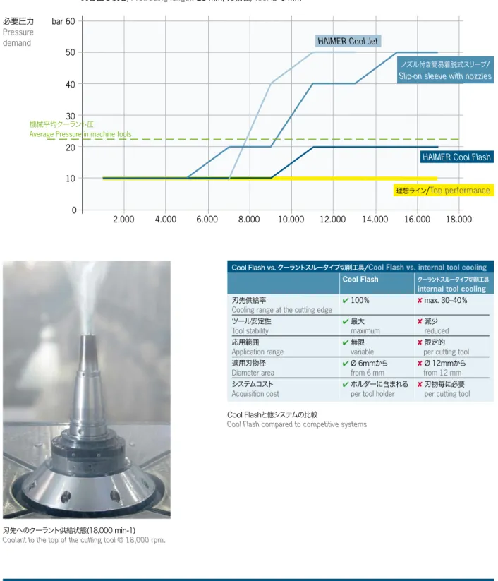
2.000 4.000 6.000 8.000 10.000 12.000 14.000 16.000 18.000 bar 60 50 40 30 20 10 0
必要圧力
Pressure demand各冷却方法による刃先に最適なクーラントが供給される状態を表記しています(クーラント圧力をY軸、主軸回
転数をX軸)。
Optimized coolant supply to the top of the cutting tool in dependence of coolant pressure and RPM
突き出し長さ/
Protruding length
: 28 mm,
刃物径/
Tool
Ø 6 mm
グラフの意味:
Graphic shows:
Cool Flash
Cool Flash追加工 注文番号/Order No. 91.100.40 Cool Flash追加工(Cool‒Jet追加工を含む) 注文番号/Order No. 91.100.41
機械平均クーラント圧
Average Pressure in machine tools
クーラント供給システム「COOL FLASH」-シミュレーション
C O O L I N G S Y S T E M C O O L F L A S H – S I M U L AT I O N
刃先へのクーラント供給状態(18,000 min-1) Coolant to the top of the cutting tool @ 18,000 rpm.
Cool Flashと他システムの比較
Cool Flash compared to competitive systems
理想ライン
/
Top performance
HAIMER Cool Flash
ノズル付き簡易着脱式スリーブ/ Slip-on sleeve with nozzlesHAIMER Cool Jet
Cool Flash vs. クーラントスルータイプ切削工具/Cool Flash vs. internal tool cooling
Cool Flash クーラントスルータイプ切削工具
internal tool cooling 刃先供給率
Cooling range at the cutting edge
✔ 100 % ✘ max. 30–40 % ツール安定性 Tool stability ✔ 最大 maximum ✘ 減少 reduced 応用範囲 Application range ✔ 無限 variable ✘限定的 per cutting tool
適用刃物径 Diameter area ✔ Ø 6mmから from 6 mm ✘ Ø 12mmから from 12 mm システムコスト Acquisition cost ✔ホルダーに含まれる
per tool holder
✘ 刃物毎に必要 per cutting tool
12
技術データは予告無く変更することがあります。 ER11 締め付け/Clamping Ø [mm] Ø D L 注文番号/Order No. 81.110.1.0 0.50 – 1.00 11,5 18 81.110.1.5 1.00 – 1.50 11,5 18 81.110.2.0 1.50 – 2.00 11,5 18 81.110.2.5 2.00 – 2.50 11,5 18 81.110.3.0 2.50 – 3.00 11,5 18 81.110.3.5 3.00 – 3.50 11,5 18 81.110.4.0 3.50 – 4.00 11,5 18 81.110.4.5 4.00 – 4.50 11,5 18 81.110.5.0 4.50 – 5.00 11,5 18 81.110.5.5 5.00 – 5.50 11,5 18 81.110.6.0 5.50 – 6.00 11,5 18 81.110.6.5 6.00 – 6.50 11,5 18 81.110.7.0 6.50 – 7.00 11,5 18 ER20 締め付け/Clamping Ø [mm] Ø D L 注文番号/Order No. 81.200.02 1.50 – 2.00 21 31,5 81.200.03 2.00 – 3.00 21 31,5 81.200.04 3.00 – 4.00 21 31,5 81.200.05 4.00 – 5.00 21 31,5 81.200.06 5.00 – 6.00 21 31,5 81.200.07 6.00 – 7.00 21 31,5 81.200.08 7.00 – 8.00 21 31,5 81.200.09 8.00 – 9.00 21 31,5 81.200.10 9.00 –10.00 21 31,5 81.200.11 10.00 –11.00 21 31,5 81.200.12 11.00 –12.00 21 31,5 81.200.13 12.00 –13.00 21 31,5 ER16 締め付け/Clamping Ø [mm] Ø D L 注文番号/Order No. 81.160.01 0.50 – 1.00 17 27 81.160.1.5 1.00 – 1.50 17 27 81.160.02 1.50 – 2.00 17 27 81.160.2.5 2.00 – 2.50 17 27 81.160.03 2.50 – 3.00 17 27 81.160.04 3.00 – 4.00 17 27 81.160.05 4.00 – 5.00 17 27 81.160.06 5.00 – 6.00 17 27 81.160.07 6.00 – 7.00 17 27 81.160.08 7.00 – 8.00 17 27 81.160.09 8.00 – 9.00 17 27 81.160.10 9.00 –10.00 17 27 ER25 締め付け/Clamping Ø [mm] Ø D L 注文番号/Order No. 81.250.1.5 1.00 – 1.50 26 35 81.250.02 1.50 – 2.00 26 35 81.250.2.5 2.00 – 2.50 26 35 81.250.03 2.50 – 3.00 26 35 81.250.04 3.00 – 4.00 26 35 81.250.05 4.00 – 5.00 26 35 81.250.06 5.00 – 6.00 26 35 81.250.07 6.00 – 7.00 26 35 81.250.08 7.00 – 8.00 26 35 81.250.09 8.00 – 9.00 26 35 81.250.10 9.00 –10.00 26 35 81.250.11 10.00 –11.00 26 35 81.250.12 11.00 –12.00 26 35 81.250.13 12.00 –13.00 26 35 81.250.14 13.00 –14.00 26 35 81.250.15 14.00 –15.00 26 35 81.250.16 15.00 –16.00 26 35高精度ERコレット
H I G H P R E C I S I O N C O L L E T S E R
–鏡面仕上げのコレットは精度及び長寿命を保証します(Haimer社製 ER コレット ホルダーと合わせて使用することを推奨します) –ISO15488(旧DIN6499)に準拠 –優れた高い把握力 –他社ERコレットホルダーにも適合 –振れ精度 5 μm– High polished finish for extra accuracy and long life, especially when clamped in HAIMER ER chucks
– ISO 15488 (formerly DIN 6499) – Superior clamping strength – Fits all brands of ER holders – Run-out accuracy 5 µm
高精度ERコレット
H I G H P R E C I S I O N C O L L E T S E R
–鏡面仕上げのコレットは精度及び長寿命を保証します(Haimer社製 ER コレット ホルダーと合わせて使用することを推奨します) –ISO15488(旧DIN6499)に準拠 –優れた高い把握力 –他社ERコレットホルダーにも適合 –振れ精度 5 μm– High polished finish for extra accuracy and long life, especially when clamped in HAIMER ER chucks
– ISO 15488 (formerly DIN 6499) – Superior clamping strength – Fits all brands of ER holders – Run-out accuracy 5 µm ER32 締め付け/Clamping Ø [mm] Ø D L 注文番号/Order No. 81.320.02 1.50 – 2.00 33 40 81.320.2.5 2.00 – 2.50 33 40 81.320.03 2.50 – 3.00 33 40 81.320.04 3.00 – 4.00 33 40 81.320.05 4.00 – 5.00 33 40 81.320.06 5.00 – 6.00 33 40 81.320.07 6.00 – 7.00 33 40 81.320.08 7.00 – 8.00 33 40 81.320.09 8.00 – 9.00 33 40 81.320.10 9.00 –10.00 33 40 81.320.11 10.00 –11.00 33 40 81.320.12 11.00 –12.00 33 40 81.320.13 12.00 –13.00 33 40 81.320.14 13.00 –14.00 33 40 81.320.15 14.00 –15.00 33 40 81.320.16 15.00 –16.00 33 40 81.320.17 16.00 –17.00 33 40 81.320.18 17.00 –18.00 33 40 81.320.19 18.00 –19.00 33 40 81.320.20 19.00 –20.00 33 40 ER40 締め付け/Clamping Ø [mm] Ø D L 注文番号/Order No. 81.400.03 2.50 – 3.00 41 46 81.400.04 3.00 – 4.00 41 46 81.400.05 4.00 – 5.00 41 46 81.400.06 5.00 – 6.00 41 46 81.400.07 6.00 – 7.00 41 46 81.400.08 7.00 – 8.00 41 46 81.400.09 8.00 – 9.00 41 46 81.400.10 9.00 –10.00 41 46 81.400.11 10.00 –11.00 41 46 81.400.12 11.00 –12.00 41 46 81.400.13 12.00 –13.00 41 46 81.400.14 13.00 –14.00 41 46 81.400.15 14.00 –15.00 41 46 81.400.16 15.00 –16.00 41 46 81.400.17 16.00 –17.00 41 46 81.400.18 17.00 –18.00 41 46 81.400.19 18.00 –19.00 41 46 81.400.20 19.00 –20.00 41 46 81.400.21 20.00 –21.00 41 46 81.400.22 21.00 –22.00 41 46 81.400.23 22.00 –23.00 41 46 81.400.24 23.00 –24.00 41 46 81.400.25 24.00 –25.00 41 46 81.400.26 25.00 –26.00 41 46
14
技術データは予告無く変更することがあります。 ER16 締め付け/Clamping Ø [mm] Ø D L 注文番号/Order No. 81.165.03 03 16,70 30 81.165.04 04 16,70 30 81.165.05 05 16,70 30 81.165.06 06 16,70 30 81.165.07 07 16,70 30 81.165.08 08 16,70 30 81.165.09 09 16,70 30 81.165.10 10 16,70 30 ER25 締め付け/Clamping Ø [mm] Ø D L 注文番号/Order No. 81.255.03 03 25,70 37 81.255.04 04 25,70 37 81.255.05 05 25,70 37 81.255.06 06 25,70 37 81.255.07 07 25,70 37 81.255.08 08 25,70 37 81.255.09 09 25,70 37 81.255.10 10 25,70 37 81.255.11 11 25,70 37 81.255.12 12 25,70 37 81.255.13 13 25,70 37 81.255.14 14 25,70 37 81.255.15 15 25,70 37 81.255.16 16 25,70 37 ER20 締め付け/Clamping Ø [mm] Ø D L 注文番号/Order No. 81.205.03 03 20,70 30 81.205.04 04 20,70 30 81.205.05 05 20,70 30 81.205.06 06 20,70 30 81.205.07 07 20,70 30 81.205.08 08 20,70 30 81.205.09 09 20,70 30 81.205.10 10 20,70 30 81.205.11 11 20,70 30 81.205.12 12 20,70 30 ER32 締め付け/Clamping Ø [mm] Ø D L 注文番号/Order No. 81.325.03 03 32,70 45 81.325.04 04 32,70 45 81.325.05 05 32,70 45 81.325.06 06 32,70 45 81.325.07 07 32,70 45 81.325.08 08 32,70 45 81.325.09 09 32,70 45 81.325.10 10 32,70 45 81.325.11 11 32,70 45 81.325.12 12 32,70 45 81.325.13 13 32,70 45 81.325.14 14 32,70 45 81.325.15 15 32,70 45 81.325.16 16 32,70 45 81.325.17 17 32,70 45 81.325.18 18 32,70 45 81.325.19 19 32,70 45 81.325.20 20 32,70 45高精度ERコレット-シール付き(クーラントスルータイプ切削工具用)-
H I G H P R E C I S I O N C O L L E T S E R – S E A L E D
–鏡面仕上げのコレットは精度及び長寿命を保証します(Haimer社製 ER コレット ホルダーと合わせて使用することを推奨します) –ISO15488(旧DIN6499)に準拠拠 –優れた高い把握力 –他社ERコレットホルダーにも適合 –振れ精度 5 μm –クーラントスルータイプ切削工具用– High polished finish for extra accuracy and long life, especially when clamped in HAIMER ER chucks
– ISO 15488 (formerly DIN 6499) – Superior clamping strength – Fits all brands of ER holders – Run-out accuracy 5 µm – Sealed for internal coolant tools
ER40 締め付け/Clamping Ø [mm] Ø D L 注文番号/Order No. 81.405.06 06 40,70 30 81.405.08 08 40,70 30 81.405.10 10 40,70 30 81.405.12 12 40,70 30 81.405.14 14 40,70 30 81.405.16 16 40,70 30 81.405.18 18 40,70 30 81.405.20 20 40,70 30 81.405.22 22 40,70 30 81.405.25 25 40,70 30
高精度ERコレットシール-COOL JET付き-
H I G H P R E C I S I O N C O L L E T S E R – S E A L E D W I T H C O O L J E T
–鏡面仕上げのコレットは精度及び長寿命を保証します(Haimer社製 ER コレット ホルダーと合わせて使用することを推奨します) –ISO15488(旧DIN6499)に準拠 –優れた高い把握力 –他社ERコレットホルダーにも適合 –振れ精度 3 μm –Cool Jet穴付き –把握シャンク h8公差以下– High polished finish for extra accuracy and long life, especially when clamped in HAIMER ER chucks
– ISO 15488 (formerly DIN 6499) – Superior clamping strength – Fits all brands of ER holders – Run-out accuracy 3 µm
– With Cool Jet bores for optimal coolant supply – For cylindrical shanks with tolerance h8 or better ER25 締め付け/Clamping Ø [mm] Ø D L 注文番号/Order No. 81.252.04 04 26 37 81.252.06 06 26 37 81.252.08 08 26 37 81.252.10 10 26 37 81.252.12 12 26 37 81.252.14 14 26 37 ER32 締め付け/Clamping Ø [mm] Ø D L 注文番号/Order No. 81.322.04 04 33 45 81.322.06 06 33 45 81.322.08 08 33 45 81.322.10 10 33 45 81.322.12 12 33 45 81.322.14 14 33 45 81.322.16 16 33 45 81.322.18 18 33 45 注意: コレットに付属している青いリングは商品識別用です。ご使用前に必ず取り除いて下さい。 Attention: Blue plastic ring is for identification purposes only and must be removed before use
16
技術データは予告無く変更することがあります。HAIMER社製パワーコレットチャック用コレット
P O W E R C O L L E T F O R H A I M E R P O W E R C O L L E T C H U C K
–3D先端で 0.003mm 以内の高い振れ精度 –優れた把握力 –HAIMER社のパワーコレットチャック専用 –把握シャンクh10公差以下の工具用 –Ø6mmからCool Jet追加工可 (ER 25、ER 32)– High runout accuracy: 0,003 mm at 3 × D – Superior clamping strength
– Fits HAIMER Power Collet Chucks – For cylindrical shanks with tolerance h10
– Optional: Cool Jet bores from Ø 6 mm at ER 25 and ER 32
ER16 締め付け/Clamping Ø [mm] D1 D2 L 注文番号/Order No. 81.163.02 2 16,45 30 81.163.03 3 16,45 30 81.163.04 4 16,45 30 81.163.05 5 16,45 30 81.163.06 61) 16,45 30 81.163.08 81) 16,45 30 81.163.10 101) 16,45 30 ER25 締め付け/Clamping Ø [mm] D1 D2 L 注文番号/Order No. 81.253.02 2 25,45 37 81.253.03 3 25,45 37 81.253.04 4 25,45 37 81.253.05 5 25,45 37 81.253.06 61) 25,45 37 81.253.08 81) 25,45 37 81.253.10 101) 25,45 37 81.253.12 121) 25,45 37 81.253.14 141) 25,45 37 81.253.16 161) 25,45 37 ER32 締め付け/Clamping Ø [mm] D1 D2 L 注文番号/Order No. 81.323.02 2 32,48 45 81.323.03 3 32,48 45 81.323.04 4 32,48 45 81.323.05 5 32,48 45 81.323.06 61) 32,48 45 81.323.08 81) 32,48 45 81.323.10 101) 32,48 45 81.323.12 121) 32,48 45 81.323.14 141) 32,48 45 81.323.16 161) 32,48 45 81.323.18 181) 32,48 45 81.323.20 201) 32,48 45
8° Ø D1 Ø D2 L – パワーコレットによる高精度把握 – 「フォーム クローズド ドライブ キー」による高トルク – 高い振れ精度 – 切削工具のスリップや抜け防止 – 工具シャンクの溝は切削抵抗に対して締まり勝手の方向に作用 – クーラントスルータイプ切削工具使用可
– High-precision Power Collets with stabilisation and concentration trough pilot of collet
– High torque due to form closed clamping – No pull out and no spinning ot the tool
– Groove on tool shank is directed so that the tool will be pulled into the chuck (depending on direction of rotation)
– Sealed for internal coolant
ER16 締め付け/Clamping Ø [mm] D1 D2 L 注文番号/Order No. 81.163.06.7 6 16,45 30 81.163.08.7 8 16,45 30 81.163.10.7 10 16,45 30 ER25 締め付け/Clamping Ø [mm] D1 D2 L 注文番号/Order No. 81.253.06.7 6 25,45 37 81.253.08.7 8 25,45 37 81.253.10.7 10 25,45 37 81.253.12.7 12 25,45 37 81.253.14.7 14 25,45 37 81.253.16.7 16 25,45 37 ER32 締め付け/Clamping Ø [mm] D1 D2 L 注文番号/Order No. 81.323.06.7 6 32,48 45 81.323.08.7 8 32,48 45 81.323.10.7 10 32,48 45 81.323.12.7 12 32,48 45 81.323.14.7 14 32,48 45 81.323.16.7 16 32,48 45 81.323.18.7 18 32,48 45 81.323.20.7 20 32,48 45
S A F E - L O C K
®機構付きパワーコレット
P O W E R C O L L E T W I T H S A F E - L O C K
® Cool‒Jet付きパワーコレット(オプション) –コレット内に最適な冷却穴装備 –切削箇所を直接冷却 –切削工具の寿命が2倍まで延びる –切削工程での高い信頼性 –構成刃先を防止 –ER25 Ø 6 mmより装着可能Optional: Cool Jet for Power Collets
– Optimized coolant bores, aimed at center in the collet – Coolant directly to the cutting edge
– Extended tool life up to 100% – Higher reliability of cutting process – No more balls of chips on tools – Starting at ER 25 Ø 6 mm
パワーコレット用COOL JET追加工
18
技術データは予告無く変更することがあります。 トルクレンチ ”トルクマスター“について: –最高の振れ精度を実現(片手ハンドルのレンチは使用しないで下さい) –常に一定の力を加えることで理想的な力の伝達が可能 –ダイヤルゲージの付いたトルクレンチを使うことで高い把握力と繰り返し精度を実 現 –的確な締め付けで高い把握力 –小径での締め過ぎを防止 –インサートの交換で標準ERコレットにも対応Two-armed torque wrench for Power Collet Chucks:
– For highest runout accuracy, no one-sided clamping – Optimal power transmission by constant force application
– Torque wrench for highest clamping accuracy and repeatability with dial gauge
– Maximum torque for highest clamping force – No overloading of smaller clamping diameters – Changeable inserts, useable also for standard ER-Collets
HAIMER社製パワーコレットチャック、ERコレットチャック用トルクレンチ ”トルクマスター“
T O R Q U E M A S T E R T O R Q U E W R E N C H F O R H A I M E R P O W E R C O L L E T
C H U C K A N D S TA N D A R D E R C H U C K S
パワーコレットチャック用トルクレンチ/Torque wrench
注文番号/Order No. サイズ/Size
84.600.00 ER 16/ER 25/ER 32
パワーコレットチャック用トルクレンチ インサート
P O W E R C O L L E T I N S E R T S F O R T O R Q U E M A S T E R
トルクマスター用インサート/ Inserts for Torque Master wrench
パワーコレットチャック用/ for Power Collet Chucks サイズ/Size 注文番号/Order No.
84.610.16 ER 16
84.610.25 ER 25
84.610.32 ER 32
標準ERチャック用/ for Standard ER Chucks サイズ/Size レンチサイズ SW/Wrench size SW
84.620.11 ER 11 SW17
84.620.16 ER 16 SW25
84.620.20 ER 20 SW30
84.620.25 ER 25
ツールクランプ
TOOL ASSEMBLY DEVICE TOOL CLAMP WITH VARIOUS ADAPTERS
工具取り付け、取り外し用治具: –安全に工具交換が可能 –素早く工具交換が可能(各種ホルダータイプにも対応) –工具交換時の事故発生を防ぐ安全設計 –バネ止めピンでホルダーを固定 –固定ピンによる安全設計 –人間工学を基準に設計し最適な工具装着を実現 –真鍮製インサートによりホルダーテーパー部に損傷を与えない設計 –必要寸法:140×100mm
The new tool assembly device:
– Secure tool assembling – Minimum locking force needed
– Quick-change function for different taper interfaces – without additional tooling – Accident-free assembling of cutting tools
– Spring-loaded locking pin – Mechanical security pin
– Better tool clamping thanks to optimum ergonomics – Replaceable brass tool pots protect the taper surface – Required space 140 x 100 mm
ツールクランプ – 4箇所×90°インデックス可能(ツールクランプ用ホルダー含まず) Tool Clamp – without tool holder, 4 x 90° indexable
注文番号/Order No. 84.700.00
ツールクランプ用ホルダー SK/BT/CAT / Tool holder SK (DIN / MAS-BT / CAT)
注文番号/Order No. タイプ/Type
84.701.30 SK / BT/ISO 30 84.701.40 SK / BT/ISO 40 84.701.50 SK / BT/ISO 50
ツールクランプ用ホルダー Capto/ Tool holder Capto
注文番号/Order No. タイプ/Type
84.705.40 Capto C4
84.705.50 Capto C5
84.705.60 Capto C6
ツールクランプ用ホルダー HSK‒A/ Tool holder HSK-A (DIN 69893/1)
注文番号/Order No. タイプ/Type
84.702.40 HSK-A40
84.702.50 HSK-A50
84.702.63 HSK-A63
84.702.80 HSK-A80
84.702.10 HSK-A100
ツールクランプ用ホルダー HSK‒C/E / Tool holder HSK-C/HSK-E (DIN 69893/1)
注文番号/Order No. タイプ/Type
84.703.32 HSK-C/E32 84.703.40 HSK-C/E40 84.703.50 HSK-C/E50 84.703.63 HSK-C/E63 84.703.80 HSK-C/E80 ツールクランプ用ホルダーHSK‒F / Tool holder HSK-F
注文番号/Order No. タイプ/Type
84.704.63 HSK-F63 84.704.80.M HSK-F80 MAKINO ツールクランプ/Tool Clamp ツールクランプ用ホルダー SK Tool holder SK ツールクランプ用ホルダー KM4X100/ Tool holder KM4X100
20
技術データは予告無く変更することがあります。ER 11–20
レンチ:フォークレンチ
for fork wrench
ER 25–40
レンチ:締め付けレンチ
for ER clamping wrench
コレットホルダー用ロックナット
L O C K N U T S F O R C O L L E T C H U C K S
ロックナット ER: –最高レベルの振れ精度 –特殊コーティングにより磨耗せず、高い把握力を実現 –プリバランスにより使用時に振動が発生しない –高速仕様プリバランス済みのHSタイプ ロックナットはオプション Locknuts ER:– Highest runout accuracy
– No wear and high clamping force due to special slide coating – Small vibrations due to pre-balancing
– Version HS fine-balanced ER ER 11 ER 16 ER 20 注文番号/Order No. 83.912… .11 .16 .20 HS タイプ/HS Version 注文番号/Order No. 83.912… .16.HS .20.HS Ø A 19 28 34 B 11,3 17 19 C M 14 x 0,75 M 22 x 1,5 M 25 x 1,5 ER ER 25 ER 32 ER 40 注文番号/Order No. 83.912… .25 .32 .40 HS タイプ/HS Version 注文番号/Order No. 83.912… .25.HS .32.HS .40.HS Ø A 42 50 63 B 20 22,3 25,3 C M 32 x 1,5 M 40 x 1,5 M 50 x 1,5
SW
SW
SW
レンチ
W R E N C H E S
ER11, 16, 20 ロックナット用レンチ(フォークレンチ)/Wrench for locknuts ER 11, ER 16 and ER 20
ER ER 11 ER 16 ER 20
レンチサイズ SW/Wrench size 17 25 30
注文番号/Order No. 84.200… .11 .16 .20
ER25~40 ロックナット用レンチ(締め付けレンチ)/Wrench for locknuts ER 25–40
ER ER 25 ER 32 ER 40
注文番号/Order No. 84.200… .25 .32 .40
フェイスミルアーバー/コンビネーション シェルエンドミル アーバー 締め付けボルト用レンチ(Ø 16–60mm) Wrench for tightening bolts for face mill arbors and combination shell end mill adapters Ø 16–60
Ø 16 22 27 32 40 50 60
注文番号/Order No. 84.400… .16 .22 .27 .32 .40 .50 .60 パワーコレットチャック用 締め付けレンチ(ER 16, ER 25, ER 32用)/Power Collet clamping wrench for ER 16, ER 25 and ER 32
ER ER 16 ER 25 ER 32
22
技術データは予告無く変更することがあります。ハイプレシジョンチャック(HG)用 コレット・内径クリーナー
H G C O L L E T S A N D H G C O N E W I P E R
ハイプレシジョンチャック(HG)用 コレット ハイプレシジョンチャック(HG)用 高精度コレット –把握シャンク h6公差以下 HG ColletsFor clamping tools with cylindrical shank with utmost precision in HG chucks.
– For tools with Shank tolerance h6
内径クリーナー
ハイプレシジョンチャック(HG)用 内径クリーナー
Cone wiper
For cleaning tool holder I.D. of HG chuck.
HG 01 Ø D [mm] 2 2,5 3 4 4,5 5 5,5 5,61) 6 6,3 7 7,11) 8 9 Ø D1[mm] 14,7 14,7 14,7 14,7 14,7 14,7 14,7 14,7 14,7 14,7 14,7 14,7 14,7 14,7 L [mm] 52,5 52,5 52,5 52,5 52,5 52,5 52,5 52,5 52,5 52,5 52,5 52,5 52,5 52,5 注文番号/Order No. 82.510… .02 .02.5 .03 .04 .04.5 .05 .05.5 .05.6 .06 .06.3 .07 .07.1 .08 .09 HG 02 Ø D [mm] 10 11 12 12,5 14 Ø D1[mm] 17,87 17,87 17,87 17,87 17,87 L [mm] 64,2 64,2 64,2 64,2 64,2 注文番号/Order No. 82.520… .10 .11 .12 .12.5 .14 HG 03 Ø D [mm] 16 18 20 Ø D1[mm] 26,147 26,147 26,147 L [mm] 69,7 69,7 69,7 注文番号/Order No. 82.530… .16 .18 .20 内径クリーナー/Cone wiper HG 01 HG 02 HG 03 注文番号/Order No. 82.590… .01 .02 03 別売りオプション/Accessories 引き抜き工具/Pull-out hook HG 注文番号/Order No. 82.570.00 潤滑剤/Lubricating paste 注文番号/Order No. 82.585.00
Cool Jet追加工/Cool Jet bores 本カタログP9参照/See page 9 注文番号/Order No. 91.100.24
23
alt old alt old 1. 2. 3. 4. 技術データは予告無く変更することがあります。 Technical data subject to change without prior noticeプルスタッド
P U L L S T U D S
プルスタッドは機械主軸と工具を繋ぐ大事な役目を果たしています。そのため、プルス タッドは精度、強度、信頼性が高く要求されます。 折れてしまったプルスタッドは加工物や機械に損害を与えるだけでなく、作業者を傷 つける恐れもあります。 そのため、質の悪いプルスタッドは単に機械の性能を下げるだけでなく、加工中に安 全を脅かす存在になりえます。 –高い強靭性を備えた特殊鋼を使用 –高度な熱処理を数段階実施 –高負荷領域での焼き戻しを実施 –高い衝撃強度 –機能面は全て研磨仕上げ –高い安全性と信頼性Pull studs are an important link between machine and tool. The requirements concerning accuracy, rigidity and reliability are very high. Pull studs of minor quality not only decrease the performance of the machine, they are even a safety risk. A breaking pull stud might cause severe damage on machine and workpiece and even injuries on persons.
– Made of special steel with high rigidity – Costly heat treatment in several steps – Spots with highest stress tempered specifically – High impact strength
– All functional surfaces fine finished after hardening – Highest security and reliability
1. ISO 7388‒3 AD(旧 DIN69872 A) センタースルー仕様/with drill through (former norm DIN 69872 Form A)
d1 d2 d3 l1 l2 l3 g1 SK 40
注文番号/Order No. 88.200.40 19 14 17 54 26 20 M16 SK 50
注文番号/Order No. 88.200.50 28 21 25 74 34 25 M24
2. ISO 7388‒3 AF(旧 DIN69872 B) O‒リング付き/sealed (former norm DIN 69872 Form B)
d1 d2 d3 l1 l2 l3 g1 SK 40
注文番号/Order No. 88.202.40 19 14 17 54 26 20 M16 SK 50
注文番号/Order No. 88.202.50 28 21 25 74 34 25 M24
3. ISO 7388‒3 UD(旧ISO 7388‒2 B) センタースルー仕様/with drill through (former norm ISO 7388-2 Form B)
d1 d2 d3 l1 l2 l3 g1 SK 40
注文番号/Order No. 88.400.40 18,95 12,95 17 44,5 16,4 11,15 M16 SK 50
注文番号/Order No. 88.400.50 29,1 19,6 25 65,5 25,55 17,95 M24
4. ISO 7388‒3 UF(旧ISO 7388‒2 B) O‒リング付き/sealed (former norm IS0 7388-2 Form B)
d1 d2 d3 l1 l2 l3 g1 SK 40
注文番号/Order No. 88.402.40 18,95 12,95 17 44,5 16,4 11,15 M16 SK 50
24
alt old 1. 2. 3. alt old l1 l2 l3 g1 d3 d2 d1 alt old alt old 4. 技術データは予告無く変更することがあります。プルスタッド
P U L L S T U D S
3. OTT仕様(センタースルー)/Ott-groove with drill through
d1 d2 d3 l1 l2 l3 g1 SK40
注文番号/Order No. 88.300.40 25 21,1 17 53 25 13,6 M16 SK50
注文番号/Order No. 88.300.50 39,3 32 25 65 25 13,35 M24 真鍮製保護リング付き/with protective ring of brass
4. OTT仕様(内面に雌ネジ付き)/Ott-groove with inner thread
d1 d2 d3 l1 l2 l3 g1 g2 SK40
注文番号/Order No. 88.303.40 25 21,1 17 53 25 13,6 M16 M16 SK50
注文番号/Order No. 88.303.50 39,3 32 25 65 25 13,35 M24 M24 SK40:真鍮製保護リング付き/SK40 with protective ring of brass
1. ISO 7388‒3 JD(旧MAS 403 30°/45°) センタースルー仕様/with drill through (former norm MAS 403 30°/45°)
d1 d2 d3 l1 l2 l3 g1 ISO 7388 旧/old BT30 注文番号/Order No. 88.605.30 11 7 12,5 43 23 18 M12 60° 30° BT40 注文番号/Order No. 88.605.40 15 10 17 60 35 28 M16 60° 30° BT40 注文番号/Order No. 88.603.40 15 10 17 60 35 28 M16 45° 45° BT50 注文番号/Order No. 88.603.50 23 17 25 85 45 35 M24 45° 45°
2. ISO 7388‒3 JF(旧MAS 403 30°/45°) センタースルー無し/without drill through (former norm MAS 403 30°/45°)
d1 d2 d3 l1 l2 l3 g1 ISO 7388 旧/old BT30 注文番号/Order No. 88.604.30 11 7 12,5 43 23 18 M12 60° 30° BT30 注文番号/Order No. 88.601.30 11 7 12,5 43 23 18 M12 45° 45° BT40 注文番号/Order No. 88.604.40 15 10 17 60 35 28 M16 60° 30° BT40 注文番号/Order No. 88.601.40 15 10 17 60 35 28 M16 45° 45° BT50 注文番号/Order No. 88.604.50 23 17 25 85 45 35 M24 60° 30° BT50 注文番号/Order No. 88.601.50 23 17 25 85 45 35 M24 45° 45° 2. 特殊/Sepcial:
ISO 7388‒3 JFに準拠したショートタイプ センタースルー無し/without drill through d1 d2 d3 l1 l2 l3 g1 ISO 7388 旧/old
BT40 ショートタイプ/shortened
alt old alt old 2. 3. 4. 5. 6.
1. 1. 森精機社仕様(MAS 90°) センタースルー無し/d1 d2 d3 l1 l2 l3 g1without drill through BT40 注文番号/Order No. 88.101.40 15 10 17 60 35 28 M16 BT50 注文番号/Order No. 88.101.50 23 17 25 85 45 35 M24
プルスタッド
P U L L S T U D S
2. ISO 7388‒2 A センタースルー仕様/Type a with drill through
d1 d2 d3 l1 l2 l3 g1 SK40
注文番号/Order No. 88.800.40 19 14 17 54 26 20 M16 SK50
注文番号/Order No. 88.800.50 28 21 25 74 34 25 M24
3. CAT-ANSI型 ヤマザキマザック社仕様(センタースルー仕様)/with drill through d1 d2 d3 l1 l2 l3 g1 CAT40
注文番号/Order No. 88.500.40 18,80 12,45 17 41,26 16,26 11,18 M16 先端にシール面付き (パイロット部Ø6mm)/
sealing on face side and pilot, inner bore Ø 6 mm CAT40 パイロット部付き/with pilot
注文番号/Order No. 88.500.40.1 18,80 12,45 17 41,26 16,26 11,18 M16 先端にシール面付き (パイロット部Ø7mm)/
sealing on face side and pilot, inner bore Ø 7 mm
4. CAT 50-ANSI型 ヤマザキマザック社仕様(センタースルー)/with drill through d1 d2 d3 l1 l2 l3 g1 CAT50
注文番号/Order No. 88.500.50 28,96 20,83 25 65,4 25,4 17,78 M24 前面にシール面付き/sealing on face side
5. CAT 40-ANSI型 ヤマザキマザック社仕様/ANSI – CAT 40 (MAZAK)
d1 d2 d3 l1 l2 l3 g1 CAT40 ロングタイプ/extended
注文番号/Order No. 88.900.40.1 18,80 12,45 17 44,11 19,11 14,03 M16 前面にシール面付き/sealing on face side
6. のこ歯ネジ プルスタッド S20 x 2/with saw thread S 20 × 2
d1 d2 d3 l1 l2 l3 g1 g2 SK40
注文番号/Order No. 88.600.40 — — 17 53 25 — M16 S20 × 2
2. JIS B 6339 センタースルー仕様/with drill through
d1 d2 d3 l1 l2 l3 g1 BT40
注文番号/Order No. 88.700.40 19 14 17 54 29 23 M16 センタースルー仕様/with drill through
BT40
注文番号/Order No. 88.701.40 19 14 17 54 29 23 M16 O-リング付き/sealed
BT50
注文番号/Order No. 88.700.50 28 21 25 74 34 25 M24 センタースルー仕様/with drill through
26
Ø D1 Ø D2 L A B A 0,01 A Ø D3 Ø D4 技術データは予告無く変更することがあります。サイドカッター アーバー
S AW B L A D E H O L D E R
用途: サイドロックホルダー用 サイドカッター アーバー シャフトタイプ: DIN 1835‒Bに準拠 焼き入れ後、内面及び外面を研削仕上げ - 締め付けボルト、スペーサー付属 - Cool Jet追加工可 Use:For holding sawblades on Weldon tool holders. Design of shank according to
DIN 1835-B
well quenched and tempered, internally and externally ground
– Included in delivery: completely with tightening bolt and intermediate disk – Cooling with Cool Jet against extra charge
サイドカッター/Sawblade Ø D1 [mm] 20 25 32 40 50 63 Ø D2 [mm] 5 8 8 10 13 16 Ø D3 [mm] 20 20 20 20 25 25 Ø D4 [mm] 10 13 16 20 25 25 L [mm] 90 100 105 110 136 136 B 0,2 mm – 6 mm 長さ A/Length A[mm] 40 50 55 60 80 80 注文番号/Order No. 79.200… .20 .25 .32 .40 .50 .63 サイドカッター アーバー セット
6種類のアーバー付属/Tool bar incl. 6 pcs. sawblade adapter 注文番号/Order No. 79.200.00 別売りオプション/Accessories 締め付けボルト/Tightening bolt サイズ/Size D1 20 25 32 40 50 63 注文番号/Order No. 79.250. .20 .25 .32 .40 .50 .63 スペーサー/Disk サイズ/Size D1 20 25 32 40 50 63 注文番号/Order No. 79.260. .20 .25 .32 .40 .50 .63 Cool Jet追加工/Cool Jet bores 本カタログP9参照/See page 9 注文番号/Order No. 91.100.24
Ø 6 Ø 6 Ø 8 Ø 10 130 100 100 Ø 6 Ø 6 Ø 8 Ø 10 130 100 100 Ø 6 Ø 6 Ø 8 Ø 10 130 100 100
HGミニ エクステンション
H G M I N I E X T E N S I O N S
HG Mini 01 円筒形状/cylindrical HG Mini 01 円錐形状/conical HG Mini 02 円筒形状/cylindrical サイズ/Size A = 100 mm A = 100 mm A = 130 mm
外径 Ø/Outer diam. 6 mm 円筒形状/cylindrical 6 – 8 mm 円錐形状/conical 10 mm 円筒形状/cylindrical
締め付け範囲 Ø/Clamping range Ø 1 – 2,5 mm 1 – 2,5 mm 2,5 – 4,5 mm 注文番号/Order No. 82.611.01 82.621.01 82.610.02
締め付け/Clamping Ø D [mm] 1 1,5 2 2,5
注文番号/Order No. 82.650. .010 .015 .020 .025
HGミニ 01用コレット/
Collets for HG Mini 01
HG Mini 01 円筒形状/cylindrical HG Mini 02 円筒形状/cylindrical HG Mini 01 円錐形状/conical 締め付け/Clamping Ø D [mm] 2 2,5 3 3,5 4 4,5 注文番号/Order No. 82.660. .020 .025 .030 .035 .040 .045 別売りオプション/Accessories
HGミニ用トルクレンチ(プリセット済み)/Torque wrench for HG Mini (pre-adjusted)
サイズ/Size 01 02
注文番号/Order No. 82.576.00 82.577.00 HGミニ用 工具取り付け治具/Assembly device for HG Mini
注文番号/Order No. 82.578.00
HGミニ 02用コレット/
Collets for HG Mini 02
HGミニ用トルクレンチ/工具取り付け治具
28
5 mm M4 7 mm +0.14 +0.10 Ø A54
技術データは予告無く変更することがあります。バランシングリング
B A L A N C I N G I N D E X R I N G S
角レンチは含まずFor fine-balancing of all tool holders with cylindrical outer diameter (diam. A). The balancing index rings have a defined unbalance in themselves. They are turned in such a position that the unbalance of the tool holder will be compensated. There are always 2 rings needed per balancing plane. – Balancing quickly and precisely
– No damage of tool holder
– Can be repeated as often as necessary – Simply fixed by clamping screw – Suitable for tool holders of all brands
– The balancing machine determines the position of the rings (e. g. HAIMER Tool Dynamic)
– Included in delivery: 2 balancing rings with clamping screws without hex wrench
1) 商品により本項に記載している不釣合い量(gmm)と若干誤差がある場合があります 円柱形状を持つツールホルダーのバランスをバランシングリングにて修正しま す。 バランシングリングには予め決められたアンバランス量があり、これをツール ホルダーのアンバランスと相殺させる位置に取り付けます。このバランシング リングは各バランス補正箇所に必ず2つ1組で使用します。 – 素早く、精密にバランス補正 – ツールホルダーに傷をつけない – 何度でも繰り返し補正が可能 – 固定ネジを締めるだけの簡単設計 – お客様のツールホルダーにもご使用可能 – HAIMER社製バランサー(TD)では補正箇所(角度)をディスプレイ上に表示 – 標準付属品:バランシングリング2個(クランプスクリューを含む) *六角レ ンチは含まず Ø A 不釣合い1)/ 最高使用回転数 [mm] unbalance rpm [1/min] 注文番号/Order No. 79.350.15 15 9 g·mm max. 55.000
79.350.16 16 11 g·mm max. 55.000 79.350.17 17 12 g·mm max. 55.000 79.350.19 19 16 g·mm max. 55.000 79.350.20 20 17 g·mm max. 55.000 79.350.22 22 20 g·mm max. 55.000 79.350.24 24 27 g·mm max. 55.000 79.350.25 25 32 g·mm max. 55.000 79.350.26 26 33 g·mm max. 50.000 79.350.27 27 33 g·mm max. 50.000 79.350.28 28 40 g·mm max. 50.000 79.350.30 30 45 g·mm max. 45.000 79.350.32 32 36 g·mm max. 45.000 79.350.34 34 40 g·mm max. 40.000 79.350.35 35 48 g·mm max. 40.000 79.350.36 36 47 g·mm max. 40.000 79.350.38 38 53 g·mm max. 35.000 79.350.40 40 57 g·mm max. 35.000 79.350.42 42 65 g·mm max. 35.000 79.350.43 43 65 g·mm max. 35.000 79.350.44 44 68 g·mm max. 35.000 79.350.46 46 75 g·mm max. 35.000 79.350.48 48 81 g·mm max. 30.000 79.350.50 50 87 g·mm max. 30.000 79.350.52 52 94 g·mm max. 30.000 79.350.53 53 86 g·mm max. 30.000 79.350.54 54 91 g·mm max. 30.000 79.350.55 55 94 g·mm max. 30.000 Ø A 不釣合い1)/ 最高使用回転数 [mm] unbalance rpm [1/min] 注文番号/Order No. 79.350.56 56 100 g·mm max. 30.000
79.350.58 58 106 g·mm max. 30.000 79.350.60 60 110 g·mm max. 25.000 79.350.62 62 120 g·mm max. 25.000 79.350.63 63 123 g·mm max. 25.000 79.350.64 64 126 g·mm max. 25.000 79.350.65 65 129 g·mm max. 25.000 79.350.66 66 120 g·mm max. 25.000 79.350.68 68 135 g·mm max. 25.000 79.350.70 70 145 g·mm max. 25.000 79.350.72 72 152 g·mm max. 25.000 79.350.74 74 160 g·mm max. 25.000 79.350.76 76 168 g·mm max. 20.000 79.350.78 78 178 g·mm max. 20.000 79.350.80 80 186 g·mm max. 20.000 79.350.82 82 199 g·mm max. 20.000 79.350.84 84 215 g·mm max. 20.000 79.350.86 86 224 g·mm max. 20.000 79.350.87 87 225 g·mm max. 20.000 79.350.88 88 226 g·mm max. 20.000 79.350.89 89 231 g·mm max. 20.000 79.350.90 90 237 g·mm max. 20.000 79.350.92 92 247 g·mm max. 20.000 79.350.94 94 253 g·mm max. 20.000 79.350.96 96 267 g·mm max. 20.000 79.350.98 98 277 g·mm max. 20.000 79.350.100 100 285 g·mm max. 15.000 79.350.125 125 295 g·mm max. 15.000
バランシングスクリューセット
S E T O F B A L A N C I N G S C R E W S
バランス修正用バランシングスクリュー (M6ネジ穴が付属している ツールホルダー に最適) *例:HAIMER社製シュリンクフィットチャ ックなど. バランシングスクリューセットには細かく等級分けした重量のネジ が付属していま す。 これらをツールホルダーのアンバランスに対し て相殺するように取り付け、バラ ンス修正を行います。 –セット内容:ネジの重量及び大きさを11種類に等級分け –使用時はネジ穴に締めこむのみで、固定ネジは必要なし –素早く、精密にバランス修正可能 –ツールホルダーに損傷を与えない構造 –何度でも繰り返し補正が可能 –お客様のツールホルダーにもご使用可能 –HAIMER社製バランサー(TD)では補正量及び角度をディスプレイ 上に表示 – 標準付属品:バランシングスクリュー 11種類×10個、ドライバーFor fine-balancing of all tool holders with balancing threads M 6 (e. g. shrink fit chucks from HAIMER).
The screws have different weights in a fine graduation. They are screwed into the balancing threads of the tool holder so that their weight compensates the unbalance of the tool holder.
– Set consisting of screws of 11 different sizes and weights – Screws are screwed to the ground of the thread and tightened.
No additional fixing of screws necessary. – Balancing quickly an precisely – No damage of tool holders
– Can be repeated as often as necessary – Suitable for tool holders of all brands
– The balancing machine calculates the necessary weight of the screws (e. g. HAIMER TOOL DYNAMIC)
– Included in delivery: Case with 11 x 10 balancing screws, screw driver
バランシングスクリューセット/Set of balancing screws 注文番号/Order No. 80.203.00
30
55
53
L G D 技術データは予告無く変更することがあります。シュリンクフィットチャック 内径用ブラシ
S H R I N K F I T B R U S H
シュリンクフィットチャックの把握力を最大限に生かすには、ホルダー内径をきれい に清潔にする必要があります。清掃にはブレーキパーツクリーナーなどを用いて下さ い。 このブラシを用いると、ホルダー内径部すべてを簡単に清掃することができます。In order to achieve the best possible shrink fit connection, a grease free socket and shank is necessary. The cleaning can be done by a cold solvent (e.g. brake cleaner). An appropriate cleaning brush is necessary to clean the socket of the Shrink Fit Chuck.
シュリンクフィットチャック 内径用ブラシ/Shrink Fit Brush Ø [mm] 注文番号/Order No. 86.200.01 3 86.200.02 3,5 86.200.02 4 86.200.02 4,5 86.200.02 5 86.200.03 6 86.200.03 8
クーラントチューブ/
C O O L A N T T U B E
–スピンドル内の汚れを防ぐ –HSKセンタースルータイプの機械用 –2個のO-リングによりスムーズに可動 –特殊コーティングにより滑らかな表面を実現 –スピンドルのシーリングシステムに損傷を与えない構造 –他社HSKホルダーにも適合– Prevents spindle from being spoiled
– Must be used with all coolant through HSK spindles – Dual o-ring design makes tube slightly movable – Special coating with extremely smooth surface – No damaging of the sealing system – Fits all brands of HSK holders
クーラントチューブ(O‒リング 2個付き)/ HSK-A32 HSK-A40 HSK-A50 HSK-A63 HSK-A80 HSK-A100 HSK-A125 Coolant tube with 2 o-rings HSK-E32 HSK-E40 HSK-E50
注文番号/Order No. 85.700… .32 .40 .50 .63 .80 .10 .125 長さ/Length G [mm] M10 x 1 M12 x 1 M16 x 1 M18 x 1 M20 x 1,5 M24 x 1,5 M30 x 1,5 長さ/Length D [mm] 6 8 10 12 14 16 18 長さ/Length L [mm] 26 29,5 33 36,5 40 44 48 別売りオプション/Accessories クーラントチューブ用レンチ/Wrench for HSK-32 HSK-40 HSK-50 HSK-63 HSK-80 HSK-100 HSK-125 注文番号/Order No. 84.500… .32 .40 .50 .63 .80 .10 .125
シュリンクフィットチャック 内径用ブラシ/Shrink Fit Brush Ø [mm] 注文番号/Order No. 86.200.04 10 86.200.04 12 86.200.06 14 86.200.06 16 86.200.07 18 86.200.07 20 86.200.08 25
56
56
56
スピンドル用クリーナー
C O N E W I P E R
ハイプレシジョンチャック(HG)内径用クリーナー/For cleaning the inner cone of HG chucks
スピンドル用クリーナー/Cone wiper HSK HSK-32 HSK-40 HSK-50 HSK-63 HSK-80 HSK-100 注文番号/Order No. 85.820… .32 .40 .50 .63 .80 .10
スピンドル用クリーナー/Cone wiper SK, BT, CAT SK40 BT40 CAT40 SK50 BT50 CAT50 注文番号/Order No. 86.100… .40 .40 .40 .50 .50 .50 スピンドル用クリーナー/Cone wiper MK MK 01 MK 02 MK 03 MK 04
注文番号/Order No. 86.100… .01 .02 .03 .04
スピンドル用クリーナー/Cone wiper HG HG 01 HG 02 HG 03 注文番号/Order No. 82.590… .01 .02 .03