ダイナミックコネクタD-5000シリーズ (DYNAMIC CONNECTOR D-5000 SERIES) 1. 適用範囲 1.1 内容 本規格はダイナミックコネクタ D-5000 シリーズの製品性 能、試験方法、品質保証の必要条件を規定している。 1. Scope 1.1 Contents
This specification covers the requirements for product performance, test methods and quality assurance provisions of Dynamic connector D-5000 series. 2. 参考規格類 以下の規格類は本規格中で規定する範囲内において、 本規格の一部を構成する。万一本規格と製品図面の間に 不一致が生じた時は、製品図面を優先して適用すること。 万一本規格と参考規格類の間に不一致が生じた時は、 本規格を優先して適用すること。 2. Applicable Documents :
The following documents form a part of this specification to the extent specified herein. In the event of conflict between the requirements of this specification and the product drawing, the product drawing shall take precedence.
In the event of conflict between the requirements of this specification and the referenced documents, this specification shall take precedence.
2.1 Tyco Electronics規格
A.114-5206 :取付適用規格 B.501-5188 :試験報告書
2.1 Tyco Electronics Specifications :
A.114-5206: Application Specification B.501-5188: Test Report
2.2 民間団体規格
A.MIL-STD-202: 電子電気部品の試験方法
B.EIA364: 電気コネクタ/ソケットの試験手順
2.2 Commercial Standards and Specifications:
A.MIL-STD-202: Test methods for Electronic And Electrical Component Parts
B.EIA364: Electrical Connector / Socket Test Procedures
3. 一般必要条件 3. Requirements:
3.1 設計と構造
製品は該当製品図面に規定された設計、構造、物 理的寸法をもって製造されていること。
3.1 Design and Construction:
Product shall be of the design, construction and physical dimensions specified on the applicable product drawing.
3.2 材料 A. コンタクト (1) 材質: 銅合金 (2) 表面処理 リセ: 全面ニッケル下地めっき 金めっき(接点部)、又は全面銀めっき タブ(ヘッダー): 全面ニッケル下地めっき 金めっき(接点部)及び 錫めっき(タイン部)又は 全面銀めっき タブ(ワイヤー): 全面ニッケル下地めっき 金めっき(接点部) B. ハウジング (1) 材質: ガラス入りポリエステル樹脂 色: 黒 (2) 難燃性: UL94V-0 C. 付属品取付金具等(リテンションレグ) (1) 材質: 銅合金 (2) 表面処理: 錫めっき 3.2 Materials: A. Contact
(1) Material: Copper alloy (2) Finish:
Receptacle: Nickel plating all over Gold plating(contact area) or Silver plating (all over) Tab(Header): Nickel plating all over
Gold plating(contact area) and Tin plating(tine area) or Silver plating(all over) Tab(wire): Nickel plating all over Gold plating(contact area)
B. Housing
(1) Material: G.F.Polyester Color: Black
(2) Flammability: UL94V-0
C. Accessories and hardware(retention reg): (1) Material: Copper alloy
(2) Finish: Tin plating
3.3 定格
A. 定格電圧 630V AC/DC
B. 定格電流 許容電流についてはFig.1参照 C. 使用温度範囲-55℃~+105℃
3.3 Ratings :
A. Voltage Rating : 630V AC/DC
B. Current Rating: Refer to Fig.4 for maximum allowable current to be applied.
金めっき製品 / Gold plating products 単位:A / Unit: A AWG 電線 Wire #16 #14 #12 #10 #8 電流 Current 16 19 25 30 35
銀めっき製品 1~3極通電の場合 / Silver plating products, 1-3pos. conducting. 単位:A / Unit: A AWG 電線 Wire #20 #18 #16 #14 #12 #10 #8 電流 Current 12 16 20 25 33 38 45
銀めっき製品 4極通電の場合 / Silver plating products, 4pos. conducting. 単位:A / Unit: A AWG 電線 Wire #20 #18 #16 #14 #12 #10 #8 電流 Current 12 15 18 23 31 35 43
Fig.1 定格電流(1極当たり) / Current rating per 1 Pos.
3.4 性能必要条件と試験方法 製品はFig.2に規定された電気的、機械的、及び耐環 境的性能必要条件に合致するよう設計されているこ と。 試験は特別に規定されない限り室温下で行われるこ と。
3.4 Performance Requirements and Test Descriptions :
The product shall be designed to meet the electrical, mechanical and environmental performance requirements specified in Fig.2. All tests shall be performed in the room temperature, unless otherwise specified.
3.5性能必要条件と試験方法の要約
3.5 Test Requirements and Procedures Summary:
項目 試験項目 規格値 試験方法
Para. Test Items Requirements Procedures
3.5.1 製品の確認 製品図面と取付適用規格 114-5206 の 必要条件に合致していること。 目視により、コネクタの機能上支障をきたす 損傷を検査する。 3.5.1 Examination of Product
Meets requirements of product drawing and Specification 114-5206.
Visual inspection No physical damage. 電気的性能 Electrical Requirements 3.5.2 総合抵抗 (ローレベル) 2mΩ 以下 ハウジングに組み込まれ嵌合したコンタクト を開路電圧50mV以下、閉路電流50mA以 下の条件で測定する。 Fig.4参照。 EIA364-23 3.5.2 Contact Resistance (Low Level)
2mΩMax Subject mated contacts assembled in
housing to 50mV Max open circuit at 50mA. Refer to Fig. 4 EIA364-23 3.5.3 耐電圧 沿面放電、フラッシュオーバー等がない こと。 リーク電流0.5mA以下 3kVAC 1分間印加。 コネクタ嵌合あり。 隣接コンタクト間で測定。 MIL-STD-202 試験法301 3.5.3 Dielectric withstanding Voltage
No creeping discharge or flashover shall occur.
Current leakage: 0.5 mA Max.
3kVAC for 1 minute.
Test between adjacent circuits of mated/ unmated connectors. MIL-STD-202 Method 301 3.5.4 絶縁抵抗 1000MΩ 以上 500VDC印加。 コネクタ嵌合あり。 隣接コンタクト間で測定。 MIL-STD-202 試験法302 条件B 3.5.4 Insulation Resistance 1000MΩ Min Impressed voltage 500 V DC.
Test between adjacent circuits of mated/ unmated connectors.
MIL-STD-202 Method 302 condition B 3.5.5 温度上昇 規定又は定格電流を通電して、温度上 昇は30℃以下 通電による温度上昇を測定すること。 Fig.5参照 EIA364-70 コネクタ: D-5200 4P,6P 水平型ヘッダー 3.5.5 Temperature Rising
30℃ Max. under loaded
specified current or rating current.
Measure temperature rising by energized current. Refer to Fig.5 EIA364-70 Connector: D-5200 4P, 6P H-Header Fig. 2 (続く) Fig. 2 (CONT.)
項目 試験項目 規格値 試験方法
Para. Test Items Requirements Procedures
機械的性能 Mechanical Requirements 3.5.6 コンタクト 保持力 49N 以上 コンタクト引抜力を軸方向に加えること。操 作速度:100mm/分 EIA364-29 3.5.6 Contact
Retention Force 49N Min.
Apply an axial pull-off load to crimped wire.
Operation Speed: 100mm/min. EIA364-29 電線サイズ 引張強度(以上) mm2 (AWG) N 0.50 #20 73.5 0.85 #18 117 1.309 #16 186 2.081 #14 245 3.309 #12 313 5.262 #10 401 3.5.7 圧着部引張強度 8 #8 401 圧着したコンタクトを試験機に固定し、軸方 向引張力を電線に加える。 操作速度は25 mm/分 EIA364-8
Wire Size Crimp Tensile(min) mm2 (AWG) N 0.50 #20 73.5 0.85 #18 117 1.309 #16 186 2.081 #14 245 3.309 #12 313 5.262 #10 401 3.5.7 Crimp Tensile Strength 8 #8 401
Apply an axial pull-off load to crimped wire of contact secured on the tester. Operation Speed : 25 mm/min. EIA364-8 3.5.8 衝撃 衝撃により1µsec.をこえる不連続導通を 生じないこと。 試験後、総合抵抗(ローレベル)の条件 に合致すること。 加速度 :490m/s2 衝撃パルス波型:正弦波 接続時間:11m sec. 速度変化:3.4m/s 衝撃回数:X,Y,Z軸正逆方向に各3回宛、合 計18回 MIL-STD-202 試験法213 条件A 3.5.8 Physical Shock No electrical discontinuity greater than 1µsec. Shall occur.
Meet requirement of
Contact resistance (2 mΩ Max.)
Accelerated Velocity :490m/s2
Waveform : sine wave Duration : 11ms
Velocity Change : 3.4m/s
Number of Drops:3 drops each to normal and reversed directions of X, Y and Z axes, totally 18 drops
MIL-STD-202 Method 213, condition A Fig. 2 (続く)
項目 試験項目 規格値 試験方法
Para. Test Items Requirements Procedures
3.5.9 コネクタ 挿入力 9.8N以下(初期値、1極当たり) 銀めっき品: 19.6N以下 (初期値、1極当たり) 操作速度100mm/分。 挿入に要する力を測定。 EIA364-13 3.5.9 Connector Mating Force
9.8N Max per 1 contact (Initial) Silver plated product: 19.6N Max per 1 contact (Initial)
Operation Speed : 100mm/min.
Measure the force required to mate connector. EIA364-13 3.5.10 コネクタ 引抜力 1.96N -19.6N(初期値、1極当たり) 操作速度100mm/分。 引抜に要する力を測定。 EIA364-13 3.5.10 Connector Unmating Force
1.96N – 19.6N per 1 contact (Initial) Operation Speed : 100mm/min.
Measure the force required to unmate connector. EIA364-13 3.5.11 コンタクト 装着力 9.8N以下(1極当たり) コンタクトをハウジングに装着するに要する 力を測定すること。 3.5.11 Contact Insertion Force
9.8N Max per 1 contact Measure the force required to insert contact into housing.
3.5.12 振動 (高周波) 振動中 1µsec.をこえる不連続導通を生 じないこと。 振動周波数:10-500Hz / 15分 加速度 :98m/s2 振動方向 :X,Y,Z 振動時間 :各2時間 MIL-STD-202 試験法204 条件A 3.5.12 Vibration(High Frequency)
No electrical discontinuity greater than 1 µsec. Shall occur.
Vibration Frequency: 10-500 / 15min. Accelerated Velocity : 98 m/s2
Vibration Direction: X,Y,Z Duration : 2 hours each
MIL-STD-202 Method 204 condition A
挿抜速度: 100mm/分 挿抜回数: めっき サイクル 金(0.38μm) 25 金(0.76μm) 50 銀(2.54μm) 25 3.5.13 耐久性 (繰り返し挿抜) 試験後、総合抵抗(ローレベル)の条件 に合致すること。 EIA364-9
Operation Speed :100mm / min No. of Cycles : Plating Cycles Gold(0.38μm) 25 Gold(0.76μm) 50 Silver(2.54μm) 25 3.5.13 Durability (Repeated Mate/Unmating Meet requirement of
Contact resistance (2 mΩ Max.).
AMP Spec. 109-5231 Fig. 2 (続く)
項目 試験項目 規格値 試験方法
Para. Test Items Requirements Procedures
3.5.14 ハウジング・ ロック強度 98N 以上 ハウジングのロック強度を測定。 操作速度50mm/分 EIA364-98 3.5.14 Housing Locking Strength 98N Min.
Measure housing locking strength. Operation Speed : 50 mm/min. EIA364-98 3.5.15 はんだ付け性 試験面は新鮮なはんだ面が95%以上で あること。 はんだ温度:235 ± 5℃ はんだ浸漬時間:5 ± 0.5秒 使用フラックス:アルファー100 MIL-STD-202 試験法208 3.5.15
Solderability Wet Solder Coverage : 95% Min.
Solder Temperature : 235 ± 5℃ Immersion Duration : 5 ± 0.5seconds Flux : Alpha 100 MIL-STD-202 Method 208 環境的性能 Environmental Requirements 3.5.16 はんだ耐熱性 試験後物理的損傷を生じないこと。 プリント基板に取り付けて試験する。 はんだ温度:260 ± 5℃ はんだ浸せき時間:10 ± 1秒 MIL-STD-202 試験法210A 条件B 3.5.16 Resistance to soldering Heat
No physical damage shall occur.
Test connector on PCB. Solder Temperature:260 ± 5℃ Immersion Duration: 10 ± 1sec
MIL-STD-202 Method 210A ,condition B 3.5.17 熱衝撃 試験後、総合抵抗(ローレベル)の条件 に合致すること 嵌合したコネクタ -55℃/30分、85℃/30分、 これを1サイクルとし25サイクル行う。 MIL-STD-202 試験法107 条件A-1 3.5.17 Thermal Shock Meet requirement of
Contact resistance(2mΩ Max).
Mated connector
-55℃ / 30min., 85℃ / 30min. Making this a cycle, repeat 25 cycles. MIL-STD-202 Method 107,condition A-1 3.5.18 温湿度 サイクリング 試験後、総合抵抗(ローレベル)の条件 に合致すること。 嵌合した/しないコネクタ25~65℃、 90~95% R.H. 10サイクル -10℃寒冷衝撃は実施しない MIL-STD-202 試験法106 3.5.18 Humidity-Tempe rature Cycling Meet requirement of
Contact resistance(2mΩ Max). Mated/Unmated connector, 25~65℃, 90~95% R.H. 10 cycles
Cold shock –10℃ not performed MIL-STD-202 Method 106
Fig. 2 (続く) Fig. 2 (CONT.)
項目 試験項目 規格値 試験方法
Para. Test Items Requirements Procedures
3.5.19 亜硫酸ガス 試験後、総合抵抗(ローレベル)の条件 に合致すること。 嵌合したコネクタ SO2ガス 10ppm, 95% R.H. 25 ℃、96時間 3.5.19 Industrial Gas (SO2) Meet requirement of
Contact resistance(2mΩ Max).
Mated connector SO2Gas: 10ppm, 95% R.H. 25 ℃, 96 hours 3.5.20 高温寿命 (耐熱) 試験後、総合抵抗(ローレベル)の条件 に合致すること。 嵌合したコネクタ 105 ℃、 250時間 MIL-STD-202 試験法108 3.5.20 Temperature Life (Heat Aging) Meet requirement of
Contact resistance(2mΩ Max).
Mated connector 105 ℃, Duration: 250hours MIL-STD-202 Method 108 3.5.21 硫化水素ガス 試験後、総合抵抗(ローレベル)の条件 に合致すること。 嵌合したコネクタ H2Sガス 10ppm, 95% R.H. 25 ℃、504時間 JIS C 0092 3.5.21 Industrial gas (H2S) Meet requirement of
Contact resistance(2mΩ Max).
Mated connector H2S Gas: 10ppm, 95% R.H. 25 ℃, 504 hours JIS spec C 0092 Fig. 2 (終り) Fig. 2 (End)
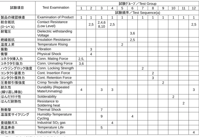
4. 製品認定試験の試験順序
4. Product Qualification Test Sequence
試験グループ/Test Group 1 2 3 4 5 6 7 8 9 10 11 12 試験項目 Test Examination 試験順序/Test Sequence(a) 製品の確認検査 Examination of Product 1 1 1 1 1 1 1 1 1 1 1 1 総合抵抗 (ローレベル) Contact Resistance (Low Level) 2,5 2,4,6 8,10 2,5 2,5 耐電圧 Dielectric withstanding Voltage 3,6 絶縁抵抗 Insulation Resistance 2,5 温度上昇 Temperature Rising 2 振動 Vibration 3 衝撃 Physical Shock 4
コネクタ挿入力 Conn. Mating Force 2,5,
コネクタ引抜力 Conn. Unmating Force 3,6
ハウジングロック強度 Conn. Locking Strength 2
コンタクト装着力 Cont. Insertion Force 2
コンタクト保持力 Cont. Retention Force 3
圧着部引張強度 Crimp Tensile Strength 2
耐久性 (繰り返し挿抜) Durability (Repeated Mate/Unmating) 4 3 3 3 はんだ付け性 Solderability 2 はんだ耐熱性 Resistance to Soldering heat 2 熱衝撃 Thermal Shock 7 温湿度サイクリング Humidity-Temperature Cycling 9 4 亜硫酸ガス Industrial SO2 gas 4 高温寿命 Temperature Life 5 硫化水素 Industrial H2S gas 4
(a)欄内の数字は試験を実施する順序を示す。/Numbers indicate sequence in which tests are performed.
電線/WIRE L AWG#8 57cm AWG#10 50cm AWG#12 42cm AWG#14 36cm AWG#16 29cm AWG#18 25cm AWG#20 20cm
Fig.5 温度上昇測定 / Measurement of Temperature rising 測定回路: ○印
Measured circuit: marked○
L L L 2L 温度測定位置 Measurement point 電線 / Wire はんだ付け Soldered 電線 / Wire
5. 品質保証条項 5. Requirements: 5.1製品認定試験 A.試料の選定 コネクタとコンタクトは該当する取扱説明書に 従って作成準備されること。試料は現行の生産 システムから無作為抽出で選定されること。 B. 試験順序 品質確認検査はFig.3に示す順序で試験を実施 し、性能要件を確かめること。 C. 試験条件 特に指定のない場合は、下記に示す環境条件の もとで性能試験を行うものとする。 5.1 Qualification Testing: A. Sample Selection:
Connector housings and contacts shall be prepared in accordance with applicable Instruction Sheets. They shall be selected at random from current production. B. Test Sequence:
Qualification inspection shall be verified by Testing samples as specified in Figure 3. C. Test Conditions:
Unless otherwise specified,all the tests shall be performed in any conbination of the test condition.
温 度/Temperature 15-35℃
相対湿度/Relative humidity 45-75%
気 圧/Atmospheric Pressure 866.6-1066.6hPa
5.2製品再認定試験 もし製品に、形状、組合せや嵌合、又は機能に 相当の影響を及ぼす変更がなされた時には、品質 保証部門は、製品開発、品質保証、信頼性技術 部門により決定された初期の試験項目全部又は その一部による製品再認定試験の実施を設定す ること。 5.2 Requalification Testing
If changes sighificantly affecting form、fit,or function are made to the product or to the manufacturing process,product assurance shall coordinate requalification testing,consisting of all or part of the original testing sequence as determined by envelopment product,quality,and reliability engineering. 5.3 製品の合格 製品性能の合格は、Fig.2の要求条件に製品が合格 することを証明して行うこと。試験の器具、設備、 試験方法の組立て方や、試験者の不慣れに起因する 試験結果不良は、製品性能の不合格と見なさない。 万一こうした理由で不良結果を生じた時は、不良原 因を修正する手段をとり、製品認定試験に必要な試 料を再び選定し、再試験を実施すること。再試験実 施前には、修正手段の適正を確認する試験を行うこ と。 5.4 品質確認検査 5.3 Acceptance:
Acceptance is based on verification that the product meets the requirements of Figure.2 Failures attributed to equipment,test get up, or operator deficiencies shall not disqualify the product. When product failure occurs,corrective action shall be taken and samples resubmitted for qualification.
Testing to confirm corrective action is required before resubmittal.