INVITED PAPER
Special Section on Future Internet Technologies against Present CrisesDevelopment of Seismometers Sensor Network for Observation on Sea Floor —— IP goes to Oceans ——
Katsuyuki YAMAZAKI†a),Fellow, Hiroshi YAMAMOTO†,Member, Masanao SHINOHARA††, andToshihiko KANAZAWA††,Nonmembers
SUMMARY Because large earthquakes have repeatedly occurred in subduction zones, it is important to observe seismic activities on the sea floor. An ocean bottom cabled seismometers (OBCS) system is the most suitable tool for this purpose since data can be obtained in real-time. Al- though the existing OBCS systems are useful for the study of seismic ac- tivities, the number of stations is limited due to their cost. Therefore, lower cost in both production and installation is desired. We have developed a new OBCS system utilizing IP technologies. IP technologies yield the new OBCS system that are more compact and less expensive, while a large amount of complex hardware is used in the existing OBCS system. System reliability is ensured by using IP network technologies that provide redun- dancy. The new OBCS system was first installed to observe the Niigata- Kobe tectonic zone in the Japan Sea on September 2010. Although this first OBCS system has a total length of 25 km, it has been proven that seis- mic data can be successfully obtained and that the new OBCS system is effective and useful for the dense observation of seismogenic activities on the sea floor around Japan.
key words: OBCS, earthquake
1. Introduction
The Japanese islands lie in subduction zones, where the Pa- cific plate subducts below the Japanese islands. Because large earthquakes have repeatedly occurred in subduction zones, it is important to observe seismic activity on the sea floor just above these seismogenic zones. Note that the main purpose of this seismic measurement is not the direct detec- tion of earthquakes but the detection of imperceptible tec- tonic activities by which the tectonic mechanism and move- ment can be analyzed and estimated for earthquake observa- tions.
Ocean bottom seismometers (OBSs) were developed for one-year observations and have been deployed in the seismogenic zone around Japan [1]. The OBS is stand-alone equipment, and is first dropped and placed on the sea floor.
It records seismic data internally, and after about a year pops-up on the sea surface after which we can finally obtain the data. Although this pop-up OBS has been widely used, it has serious problems such as limited power, low reliabil- ity of data recovery, and off-line observation for long-term seismic activities.
Manuscript received November 4, 2011.
Manuscript revised February 27, 2012.
†The authors are with the Department of Electrical Engineer- ing, Nagaoka University of Technology, Nagaoka-shi, 940-2188 Japan.
††The authors are with the Earthquake Research Institute, The University of Tokyo, Tokyo, 113-0032 Japan.
a) E-mail: [email protected] DOI: 10.1587/transcom.E95.B.2182
Ocean bottom cabled seismometers (OBCS), where the sensors are equipped in a hermetically-sealed case and these cases are connected with cables, is the best solution to ad- dress these problems. Note that OBCSs can be used to de- tect the occurrence of earthquakes in real time, while OBSs cannot. The first OBCS system, consisting of eight cabled seismometers (CSs), was developed by the ERI (earthquake research institute), University of Tokyo, based on a subma- rine telecommunication cable system, and has been used over the past 25 years in Japan [2], [3]. Although this ex- isting OBCS system has made a significant contribution to the study of seismic activity, the number of seismometers is insufficient for high resolution observations of the seismo- genic zone. The high cost is a problem that must be resolved to consider a sufficient number of seismometers. This is the critical problem in the existing OBCS system [4]–[6].
In addition to the problem of cost, the existing OBCS system has become insufficient to meet today’s require- ments, particularly in flexibility of measurements after in- stallation. A portable system is also required and is expected to be used for the precise monitoring of seismic activity after large earthquakes and so on.
After substantial consideration of interdisciplinary re- search studies with engineers of various fields, such as ocean engineering, metrology, electronic engineering, mechani- cal engineering, and information and communication engi- neering in particular, it was concluded that IP technologies should be utilized for a new OBCS system, i.e., IP should be used for OBCSs at the bottom of the ocean.
In accordance with this concept, we have developed a new OBCS system. While a large amount of complex hard- ware is used in the existing OBCS system, the new OBCS system can be made compact since software processes vari- ous measurements. Reliability of the system is achieved by using a redundant system that is constructed with IP network technologies.
The new OBCS system was first installed to observe the Niigata-Kobe tectonic zone in the Japan Sea on Septem- ber 2010. Although this first OBCS system has a total length of 25 km, it has been proven that seismic data can be suc- cessfully obtained and that the new OBCS system is effec- tive and useful for a dense observation of seismogenic zones on the sea floor around Japan.
This paper is organized as follows. Section 2 addresses the backgrounds and objectives of the new OBCS system.
Section 3 outlines the proposed architecture and system de- Copyright c2012 The Institute of Electronics, Information and Communication Engineers
sign. Section 4 presents the details of the developed system as well as evaluation results of Linux/IP and a network. Sec- tion 5 gives the first installation of the OBCS system in the Japan Sea near Awashima Island, Niigata Prefecture. Con- clusions are given in Sect. 6.
2. Backgrounds and Objectives of the New OBCS Sys- tem
There are already approximately 2,000 land-based seismic observatories in Japan. On the other hand, the number of seismic observatories in the oceans is quite limited, and fur- thermore those OBCSs are configured in a line. Figure 1 shows existing OBCSs around Japan, where c) and e) are operated by the ERI and the others are operated by other organizations. All of these OBCSs are installed in a quite short line; hence they are not sufficient to measure seismic activities precisely on the sea floor. Note that the circles in Fig. 1 indicate areas where careful seismic observations are required.
Our objective is to develop a high density of observa- tion points in the emerging seismogenic ocean areas that will be sufficient to achieve the same level of observation as the land-based networks. Seismic measurements in the ocean should be performed over a planar area rather than only over a line of points.
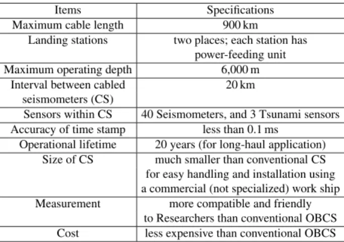
Figure 2 depicts the conceptual scheme for the new long-haul application OBCSs. CSs are equipped with op- tical cables and placed at 20 km intervals. Optical cables are installed for up to 900 km with a continuous “S” pat-
Fig. 1 Existing OBCS system — Observation in a line.
tern, by which the CSs are distributed on a plane. There- fore, the seismic observatories would be on a planar level, and the density of observatories on the ocean bottom would be equivalent to that on the land. When this system is used at the maximum length, it is composed of 40 CSs and three tsunami sensors.
Objective specifications for the new OBCS are given in Table 1. The operational depth is set to 6,000 m, so the system can be used for almost all targeted areas of the ocean bottom around Japan. The accuracy of the time stamp is less than 0.1 ms, which is equal to the present accuracy. The system is expected to be in use for more than 20 years.
The most important objective of the new OBCS system is reducing the cost of both development and installation.
The size of the CS is the key to achieve this requirement.
A smaller CS leads to lower costs for development. When the CSs are sufficiently small, ordinary ships, rather than specialized cable ships that are used for the existing OBCSs, can be utilized to install the OBCS, and the installation costs can be significantly reduced.
In addition, measurement must be more compatible and
Fig. 2 Concept of new OBCS system — Observation on a plane.
Table 1 Objective specifications of the new OBCS system.
Items Specifications
Maximum cable length 900 km
Landing stations two places; each station has power-feeding unit
Maximum operating depth 6,000 m
Interval between cabled 20 km
seismometers (CS)
Sensors within CS 40 Seismometers, and 3 Tsunami sensors Accuracy of time stamp less than 0.1 ms
Operational lifetime 20 years (for long-haul application) Size of CS much smaller than conventional CS for easy handling and installation using a commercial (not specialized) work ship Measurement more compatible and friendly
to Researchers than conventional OBCS Cost less expensive than conventional OBCS
user-friendly for researchers, for example, allowing chang- ing of measurement parameters after installation. These re- quirements can be met by utilizing IP technologies, as de- scribed in Sect. 3.
3. Basic Architecture and System Design of the New OBCS
3.1 Network
The conceptual network configuration for the new OBCS and the terrestrial network is schematically shown in Fig. 3.
This cable network adopts two dual methods, i.e., one is a ring configuration, and the other is a doubled ring configura- tion. A CS is equipped to a ring at 40 km intervals, i.e., a CS is installed with 20 km intervals on the ocean bottom due to the doubled ring configuration. This scheme is employed to enable both high reliability and low cost. Ethernet, which is a de-facto standard in IP area, is used as transmission system for this doubled ring configuration.
Data collected with a time stamp at each CS are trans- mitted using standard IP data transmission to landing sta- tions. The two landing stations are equipped with a power supply, a storage system, and access to the Internet. When broadband is available between the landing stations and the control center (ERI), data can be directly sent to the control center. When broadband connections can not be available, which would most likely occur as the OBCS will be installed in rural areas, the data is stored at the landing stations and is accessible by researchers through the non-broadband Inter- net.
A GPS clock at each landing station is used as a time reference to synchronize each CS, and is fed to each CS through a dedicated line, i.e., Ethernet is not used. Methods of clock transmission have been studied, and it was found that the latest clock synchronization system over Ethernet is
Fig. 3 Conceptual network configuration.
sufficient for OBCS [6], [7]. In particular, IEEE-1588 is use- ful for a land-based system clock synchronization method, as the number of cables is reduced. After evaluation of clock systems including IEEE-1588, it was, however, decided that a simple dedicated line for clock distribution should be used, because for a system in the ocean: 1) a dedicated line is not so costly, and 2) a simple configuration can realize high re- liability [6], [7].
3.2 Why IP?
The existing OBCS consists of 100% hardware. All aspects of IP technologies have been studied, and it was concluded that the use of IP for OBCS is timely, when taking account of the following advantages:
1) Making OBCS compact:
Software is capable of processing various measurements, while the existing OBCS is composed of a large amount of complex hardware.
2) Making OBCS less expensive:
Use of a central processing unit (CPU) and large scale inte- gration (LSI) can significantly reduce the number of circuits and parts.
3) Enabling IP access to OBCS:
Researchers can access OBCS via IP protocol, thus enabling quick analysis of seismogenic characteristics.
4) Enabling upgrade of OBCS:
Researchers can change measurement parameters, thus en- abling detailed and investigative measurement.
5) Enabling preventive maintenance of OBCS:
Software continuously monitors the status of parts, and alerts when necessary (e.g., power down of laser transmit- ters).
3.3 Why Linux?
There are several software platforms, i.e., operating sys- tems (OS), as candidates for OBCS. In particular, 1) Linux, 2) conventional real-time OS, and 3) Windows embedded (known as Windows mobile) OS have been studied. Con- ventional real-time OS have advantages in several metrics, i.e., processing performance, proven experiments for indus- trial use and software stability.
However, conventional OS are not compatible with IP.
At most, the objective of the new OBCS is to provide ease of access to the OBCS once installed at the ocean bottom.
IP has to be supported so that researchers can access OBCS in just the same manner as they access machines at labora- tories. The performance and reliability issues of Linux have been addressed and evaluated as shown in the next Sect. 3.4.
It was finally concluded that Linux is mature enough and acceptable for use with OBCS.
With regard to the Windows Mobile OS, it was consid- ered to be still pre-mature for OBCS application, since 1) performance for real-time processing is not sufficient, and 2) there is uncertainty as to the stability of the software, i.e., Windows Mobile has been version-upgraded so many times in the last few years.
3.4 Reliability and Performance Issues of Linux
One can raise reliability issues for Linux, as the software has become non-operational so many times. Therefore, the fol- lowing solutions have been adopted for OBCS application;
1) Ring configuration:
Each Linux OS can be accessed from both landing sta- tions.
2) Restart procedures:
The Linux OS can be restarted from landing stations through the dedicated clock line (not Ethernet lines).
Another issue for Linux or a software-based system is performance, i.e., whether or not Linux can realize sufficient real-time processing. To cope with this issue, the following two solutions were adopted:
1) Sensor data can be processed with a high priority mode (an interrupt mode is used only for sensor data).
2) Other operations, e.g. monitoring circuits, can be pro- cessed with a low priority mode (periodically pro- cessed with 1 min intervals, etc.).
An example of a developed Linux system for evalua- tion is presented in Sect. 4.
Fig. 4 Addressing and routing of OBCS.
3.5 Addressing and Routing of OBCS System
In order to minimize hardware circuits of CS and to real- ize simple configuration, layer 2 networking technology has been adopted. Furthermore, a layer 2 switching is imple- mented as a part of FPGA. Figure 4 shows addressing and routing of OBCS. A Linux of CS has four Ethernet ports, where a subnetwork IP address is assigned to each Ethernet port. A Linux also keeps an IP address of a current commu- nication port. On the other hand, a layer 2 switching has two switching pattern, i.e., strait connection and cross connec- tion. These parameters, i.e., a current communication port and layer 2 switching pattern, can be sent to CS by a ded- icated control information over a clock link. Researchers will have to set these parameters carefully from a server of landing stations.
We have studied the use of commercial layer 2 switch and layer 2 networking technologies such as a spanning tree protocol, but concluded to develop the above men- tioned manually controlled layer 2 networks in order to make OBCS as much as simple. For the same reason, IP version 4 private addressing has been adopted, since there is no reason to use IP version 6.
A Linux may freeze or hang up due to unexpected er- rors or so. A communication through Ethernet line can not be effective in that case. In order to restart a Linux, a control signal is sent over a clock link. So, the clock link conveys clock signals as well as control information such as layer 2 switching parameters and a restart signal to each Linux.
Clock links are also duplicated so that signals can be sent to CS from both landing stations.
3.6 Reliability of the Entire OBCS System
Since the Linux reliability issues have been resolved, as pre- sented in Sect. 3.4, the OBCS system itself obtains ultimate reliability due to the Linux/software-based operations. Fig- ure 5 schematically depicts an example of network opera- tions.
Under normal operation, the data from each CS can be sent to the landing stations with load balancing. When one landing station is due for maintenance, the data from all CS can be sent to the other landing station. This operation can be set by researchers via IP/Ethernet access from the control station or a landing station. Once a fiber cable is broken,
Fig. 5 High reliability and maintenancebility of the new OBCS.
Fig. 6 Performance monitoring for preventive maintenance.
which is likely to happen within a lifetime of 20 years, data from the CSs can be sent to an individual landing station through an accessible path.
Further ideas have been introduced to realize ultimate reliability, and these are depicted in Fig. 6. By utilizing Linux and IP technologies, OBCS can now be maintained by performance monitoring. The Linux OS continuously monitors the status of parts and circuits, e.g. laser transmit- ting power of E/O, the temperature within a pressure vessel, voltages of power units, and so on. The Simple Network Management Protocol (SNMP) is a de-facto protocol in IP, and is used in the OBCS system for this purpose.
When performance degradation is detected, researchers are able to re-configure the network. This makes it possible to configure the network if it is still workable, hence avoid- ing serious problems such as an isolated CS due to multiple failures. The network can be configured as ring>dual line
>single line, depending on failures and trouble. Data from each CS can be sent (retrieved) at least when a path to that CS can be configured.
4. Developed System and Evaluation
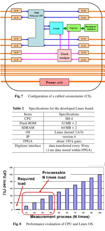
4.1 Linux and Clock Board
Based on studies of the architecture and system mentioned in Sect. 3, the new OBCS system was developed. Figure 7 shows the configuration of a CS. The Linux OS is able to access two Ethernet lines (upper and lower), as indicated in Fig. 7, depending on the engineered network configuration.
The clock module derives a GPS clock signal from the land- ing stations, as well as control signals such as Linux restart.
Fig. 7 Configuration of a cabled seismometer (CS).
Table 2 Specifications for the developed Linux board.
Items Specifications
CPU SH-4
Flash ROM 32 MB×2
SDRAM 64 MB×2
OS Linux (kernel 2.6.9)
IP version 4
FPGA about 150 k gates
Digitizer interface data transferred every 30 ms (1 ms data stored within FPGA)
Fig. 8 Performance evaluation of CPU and Linux OS.
Table 2 shows the specifications for the developed Linux board. SH-4 is a widely used industrial microproces- sor over which Linux version 2.6.9 is installed. The field- programmable gate array (FPGA) on the board handles the interface to a digitizer, and stores 30 ms of data. Linux re- trieves data every 30 ms and then sends it to the landing sta- tions.
The performance of the Linux OS has been evaluated, and the results are presented in Fig. 8. As expected, pro- cessing of the required measurement operations is done by a few CPU load. The result also indicates that the combina- tion of the SH-4 CPU and the Linux OS is capable of han- dling approximately 40 times of the required measurement
Table 3 Specifications of the developed digitizer board.
Items Specifications
Seismometer force balance accelerometer
Axis three (X, Y, Z)
Range ±2.5G
Resolution 1µG
Amplitude bandwidth DC-300 Hz
Digitizer 24 bits sigma-delta A/D converters
Sampling rate 1 kHz (1 ms)
Time stamp 0.1 ms
Fig. 9 Network model for performance evaluation.
operations. This means that researchers are able to add more functions and operations to the board as necessary.
4.2 Seismometers, Digitizer and Clock
Specifications for the developed digitizer and seismometer are given in Table 3. The seismometer is a conventional force balance accelerometer (JA-5, Japan Aviation Electron- ics Industry, Ltd.), which is a single axial type. The JA- 5 accelerometer has been used for the ocean bottom cable systems of ERI, JAMSTEC, and NIED (National Research Institute for Earth Science and Disaster Prevention). Each output of three accelerometers (X, Y, Z components) is syn- chronously digitized by 24 bit sigma-delta A/D converters with a sampling rate of 1 kHz.
A GPS clock signal from the landing stations is input to the digitizer, i.e., not through Linux, so that accurate 0.1 ms time stamping is performed using 100% hardware.
4.3 Data Transfer Methods and Evaluation of Network Performance
Digitized data is input to CPU every 1 ms, then redundant part is deleted, and it comes to 41 bytes per 1 ms. In order to simplify data transfer, 30 ms data is packed into 1 IP packet, i.e., 41×30+28 (UDP/IP header)=1,258 bytes within 1 packet. Here, we do expect very low packet loss since trans- mission paths are provided by optical fibers, and realtime transmission is necessary for emergency operations, such as earthquake detection etc. So, UDP is chosen as transport protocol. Note that 30 ms is considered as satisfactory small for emergency operations.
We have conducted evaluation of network performance of new OBCS system. Figure 9 depicts a network model for NS2 simulation. Propagation delay between two adjacent
Fig. 10 Simulation results — Latency vs. number of CS.
Fig. 11 Simulation results — Occupancy vs. number of CS.
CSs is set as 0.2 ms, and a delay within an L2 switch is as- sumed negligible. Figure 10 shows simulation results about latency which expresses a transfer delay from the most re- mote CS to a host server. When the number of CS is 20, as indicated in Table 1 and Fig. 3, the latency is less than 5 ms. Figure 11 shows simulation results about occupancy of 100 Mbps Ethernet at an ingress port of a server. When the number of CS is 20, the occupancy becomes only 5%.
The reason why both latency and occupancy comes to a linear characteristics is that data generated by CS is regu- larly and periodically transferred to a server. We may con- sider fluctuation of this interval due to CPU’s possessing time, but such fluctuation is expected to be small and 5 ms latency and 5% occupancy are considered as safe enough for reliable transfer of CS data.
Figures 10 and 11 also indicate that this system can support up to about 100 CSs on 1 ring, i.e., 200 CSs in total, with a reasonable latency and occupancy from net- work performance viewpoints. The maximum number of CS is, therefore, subject to a power consumption of CS, since there’s a limit of a DC voltage supplied at a landing station. We’ll have to continue to study for further reducing a power consumption of CS.
4.4 Packing of New OBCS
Consolidated studies for packing of the CS have also been performed, because the size of the CS is a critical issue for
Fig. 12 Packing of the new CS.
Fig. 13 Comparison of the existing and new CS.
minimization of the costs, as discussed in Sect. 2. Figure 12 shows an approximate 3D image of the new packing method for the OBCS. There are only 5 boards; Linux, clock and 3 digitizers, for the CS, and the board is approximately 7× 7 cm2.
The size of the CS is 13 cm in diameter and 50 cm long, which is almost equal to that of a 2 litter plastic drink bottle.
Compared to the existing OBCS, which has a 22 cm diame- ter and is 150 cm long, this is a remarkable reduction in size (See Fig. 13). Like communication cable system, OBCS should be buried in adjacent sea of Japan taking account of influence to inshore fishing industries. So, this small size of CS will make a burying method and construction easy, quick and less expensive.
5. First Installation of New OBCS at Japan Sea Because the development of the OBCS system has been completed, we decided to product a practical system and de- ploy the new OBCS system in the field. Global Positioning System (GPS) observations with a dense station distribution revealed that the central coastal area of the Japan Sea has large strain rate, which is named the Niigata-Kobe Tectonic Zone (NKTZ) [8] (See Fig. 1). Recently, there were three large earthquakes (the 2004 Chuetsu Earthquake, the 2007
Fig. 14 The first installation of new OBCS — Japan sea on Sept. 2010.
Fig. 15 VPN between landing station and ERI.
Noto-Hanto Earthquake, and the 2007 Chuetsu-oki Earth- quake) in and around the NKTZ. From these reasons, we decided to install the first practical OBCS system in the ma- rine area of the NKTZ.
Due to a limitation of the budget, the OBCS system for the first field installation has a total length of 25 km and 4 CSs with 5 km interval (See Fig. 14). Although the total length of the system and intervals of CSs are short compared to the conceptual design, this small size system is effective for earthquake observation since the target area is small and earthquakes occur at shallow depths. It is, of cause, aimed at proving and evaluating the new OBCS system with a small size system.
The data transmission channel using the Ethernet is du- plicated and one of the Ethernet channels is turned in the furthest CS for ring configuration. So, the network itself is a ring configuration as the same as the conceptual architec- ture in Fig. 2, though it looks like an existing line configu- ration. We’ll be able to prove and evaluate various features of the new OBCS such as changing network operations, per- formance monitoring for preventive maintenance, etc. as de- scribed in Sects. 3 and 4.
At the landing station, the data are stored in a large disk array system. In the case that the Internet has enough
capacity from the landing station to the data center, all the data from the CSs are transmitted to the data and control center at the ERI. In the case that the capacity of the Internet is limited, the system status of the OBCS and a part of the data are sent to the ERI. If a remarkable event occurs, all the data of the event will be retrieved via the Internet. The system control commands will be sent from the ERI. A VPN (Virtual Private Network) is configured between a landing station and ERI as shown in Fig. 15.
Since the installation of new OBCS on September 2010, seismic data has been sent to ERI and been con- tributed to earthquake researches.
6. Conclusions
A new OBCS system has been presented in detail, particu- larly how the application of IP technologies makes it pos- sible to realize new features. IP technologies have enabled the new OBCS system to become more compact and less expensive and enabled IP access and the upgrade of OBCSs for measurement flexibility and expandability of measure- ments. The IP-based OBCS system has the following re- markable advantages:
1) The new compact OBCS can be made very compact since software processes various measurements, while a large amount of complex hardware is used in the ex- isting OBCS.
2) Both the production and the installation of the compact OBCS is not expensive. Since a specific cable ship with high operation cost is no longer necessary, the compact OBCS can be used portably and timely to monitor the aftershocks that occur after huge earthquakes.
3) Reliability of the system is kept by using a redundant system that is easily constructed using IP network tech- nologies.
4) The OBCSs installed on the sea floor can be accessed through IP protocol on UNIX systems on land. This will enable the efficient and quick study of seismogenic characteristics.
5) Because of the software-based OBCSs, it will be pos- sible to change the measurement parameters of seis- mometers after installation, thus enabling detailed and investigative measurement.
The size of the new OBCS is 13 cm in diameter and 50 cm long, which is a remarkable reduction in size. We have evaluated particularly 1) CPU processing performance and 2) latency and occupancy of a network, by which it has been proven that the developed system satisfactorily meets design requirements.
The first OBCS system has a total length of 25 km and 4 CSs at 5-km intervals and has been deployed in the coastal area of the central Japan Sea, where large earthquakes oc- curred recently. Since the installation of this first OBCS system on September 2010, seismic data has been sent to ERI and has contributed to earthquake research.
The performance evaluation has revealed that the max-
imum number of CS may become 200 in total with a rea- sonable latency. There is, however, a limit of a DC power supplied at a landing station. Therefore, we’ll continue to study for further reducing a power consumption of CS by e.g., integrating three digitizer boards into one FPGA and so on. This will contribute to reduce the size of CS. Network management system will also be developed in the next ver- sion, since it’ll be difficult to manage manually 200 CSs and layer 2 switching functions. If these objectives will be met, then we’ll see, e.g., the maximum of 200 CSs with 5,000 km, long-haul observation system, which is effective enough for seismic observation in the oceans around Japan.
Acknowledgments
The authors would like to thank the technical commit- tee members of this interdisciplinary research, S. Sakai, O. Sano, H. Utada, H. Shiobara, Y. Morita, T. Yamada of ERI, the University of Tokyo, Y. Shirasaki of Ma- rine Eco Tech Ltd., J. Kojima of KDDI R&D Labs., Inc., K. Yamamoto, S. Chiba and Y. Jyono of LINK Labs. Inc., K. Furukawa of Intertechno Co., Ltd., R. Morikawa and H. Shirani of OCC Corp., K. Asakawa, K. Mitzuzawa and K. Kawaguchi of JAMSTEC, who have all made substantial contributions to the development of the new OBCS.
References
[1] T. Kanazawa, T. Yamada, M. Shinohara, S. Sakai, and M. Mochizuki,
“Robot seafloor seismometer for a long-term earthquake observation,”
Chikyu Monthly, Special, vol.51, pp.176–180, 2005.
[2] T. Kanazawa and A. Hasegawa, “Ocean-bottom observatory for earth- quakes and Tsunami offSanriku, North-Eastern Japan using subma- rine cable,” Proc. International Workshop on Scientific Use of subma- rine Cables, pp.208–209, Okinawa, Japan, Feb. 1997.
[3] H. Mikada, K. Hirata, H. Matsumoto, K. Kawaguchi, T. Watanabe, R.
Otsuka, and S. Morita, “Scientific results from underwater earthquake monitoring using cabled observatories,” Proc. International Work- shop on Scientific Use of submarine Cables and Related technologies (SSC’03), pp.3–7, Tokyo, Japan, June 2003.
[4] T. Kanazawa, H. Utada, S. Sakai, O. Sano, H. Shinobara, M.
Shinohara, Y. Morita, and T. Yamada, “Study on new ocean bottom cable system for research of high resolution observation of seismic activity,” CDR Proc. International Workshop on Scientific Use of Sub- marine Cables and Related Technologies (SSC’06), Dublin, Ireland, Feb. 2006.
[5] T. Kanazawa, H. Utada, S. Sakai, O. Sano, H. Shinobara, M.
Shinohara, Y. Morita, and T. Yamada, “Study on new low cost ocean bottom cabled seismometers,” Proc. OCEANS’06 IEEE Asia Pacific, Singapore, May 2006.
[6] T. Kanazawa, M. Shinohara, S. Sakai, O. Sano, H. Utada, H.
Shinobara, Y. Morita, T. Yamada, and K. Yamazaki, “A new low cost ocean bottom cabled seismometers,” CDR Proc. International Work- shop on Scientific Use of Submarine Cables and Related Technologies (SSC’07), Tokyo, Japan, April 2007.
[7] T. Kanazawa, M. Shinohara, S. Sakai, O. Sano, H. Utada, Y. Morita, T.
Yamada, and K. Yamazaki, “A new OBCS: Ocean bottom cabled seis- mometer,” Proc. IEEE OCEANS’08, IEEE Asia Pacific, Kobe, Japan, April 2008.
[8] T. Sagiya, S. Miyazaki, and T. Tada, “Continuous GPS array and present-day crustal deformation of Japan,” Pure Appl. Geophys., 157, pp.2303–2322, 2000.
Katsuyuki Yamazaki received B.E. and D.E degrees from the University of Electro- communications and Kyushu Institute of Tech- nology in 1980 and 2001, respectively. At KDD Co. Ltd., he had been engaged in R&D and in- ternational standardization of ISDN, S.S. No.7, ATM, L2, IP, mobile and ubiquitous networks, etc., and was responsible for R&D strategy of KDDI R&D Labs. Since 2006, he has been a Professor of Nagaoka University of Technol- ogy. He was a Visiting Professor and Liason Researcher of Earthquake Research Institute, the University of Tokyo, for 2007–2011.
Hiroshi Yamamoto received M.E. and D.E.
degrees from Kyushu Institute of Technology, Iizuka, Japan in 2003 and 2006, respectively.
From April 2006 to March 2010, he worked at FUJITSU LABORATORIES LTD., Kawasaki, Japan. Since April 2010, he has been an As- sistant Professor in the Department of Electri- cal Engineering, Nagaoka University of Tech- nology. His research interests include com- puter networks, distributed applications, and networked services. He is a member of the IEEE.
Masanao Shinohara is a professor of ma- rine seismology at the Earthquake Research In- stitute, the University of Tokyo. His researches into earthquake generation and structures of the Earth have contributed to the development of new observation apparatuses in the marine en- vironment. Recently, his interest aims to the de- velopment of a new ocean bottom cabled seis- mometer system and the first system was de- ployed in the Japan Sea in 2010.
Toshihiko Kanazawa is an emeritus pro- fessor of ocean bottom seismology at Earth- quake Research Institute, the University of To- kyo. He developed the most successful pop-up type OBS and more than 400 of his equipment have been used. His recent research includes marine geodetic instrumentation. At the present, he plays an important role in the construction of large-scale ocean bottom cabled seismometer and pressure gauge systems which will be de- ployed offTohoku district, North-Eastern Japan.