LETTER
An Adaptive Bit Allocation for Maximum Bit-Rate Tomlinson-Harashima Precoding
Shigenori KINJO†a)andShuichi OHNO††b),Members
SUMMARY An adaptive bit allocation scheme for zero-forcing (ZF) Tomlinson-Harashima precoding (THP) is proposed. The ZF-THP enables us to achieve feasible bit error rate (BER) performance when appropriate substream permutations are installed at the transmitter. In this study, the number of bits in each substream is adaptively allocated to minimize the average BER in fading environments. Numerical examples are provided to compare the proposed method with eigenbeam space division multiplexing (E-SDM) method.
key words: Tomlinson-Harashima precoding, maximum bit-rate, zero- forcing THP, adaptive bit allocation
1. Introduction
Eigenbeam space division multiplexing (E-SDM) is a well- known linear precoding MIMO scheme, in which precoding and decoding matrices are given by singular-value decom- position (SVD) or eigenvalue decomposition of a MIMO channel matrix[1]. E-SDM is optimum in terms of bit-rate when a water-filling (WF) is applied to determine the trans- mit power[2]. Computationally reasonable bit and power allocation methods have been studied in[3],[4]for E-SDM.
The SVD, however, remains requiring a high computational cost [5], which cannot be ignored from a practical view- point.
Tomlinson-Harashima precoding (THP) is a non-linear precoding scheme, which shows feasible bit-rate and bit er- ror rate (BER) performance, whose precoder is given by rel- atively low complexity algorithms such as QR or Cholesky decompositions [6], [7]. THP has been studied for more than two decades, whose new attractive characteristics have been studied in the last five years[7]–[10].
For MIMO systems, we have proposed a simple pre- coding scheme based on zero-forcing (ZF) THP [7], [8].
The ZF-THP has two characteristics: permutation of the transmitted signals and unequal bit allocation. More specif- ically, substream permutations are installed at the transmit- ter, and its permutation pattern is selected so as to maximize its bit-rate or sum-rate. For convenience, we call the ZF- THP a maximum bit-rate (MBR) THP. In the MBR-THP, a MIMO channel is decomposed into independent paral-
Manuscript received April 5, 2019.
Manuscript revised July 4, 2019.
†The author is with the Japan Coast Guard Academy, Kure-shi, 737-8512 Japan.
††The author is with the Graduate School of Engineering, Hiro- shima University, Kure-shi, 739-8527 Japan.
a) E-mail: [email protected] b) E-mail: [email protected]
DOI: 10.1587/transfun.E102.A.1438
lel substreams, which is similar to the decomposed MIMO channel in E-SDM. Each parallel substream has one gain like a singular value of the MIMO channel matrix. By us- ing this specific characteristic, a different number of bits has been allocated to each substream to improve the BER performance[8]. The scheme has been computationally ef- ficient and achieved relatively good BER performance in comparison to the other precoding schemes if an appropriate bit allocation pattern is selected. The pattern of the bit allo- cation has been fixed to avoid the additional computational cost for the bit allocation. This fixed bit allocation strategy is, however, generally not appropriate for time-varying fad- ing MIMO channels.
In this letter, we apply an adaptive bit allocation to the MBR-THP to improve its performance. We determine the best bit allocation pattern for a given MIMO channel to keep good performance of the MBR-THP even in slowly time- varying MIMO channels. We apply the bit allocation origi- nally developed for E-SDM[3]to the MBR-THP. However, unlike the scheme in[3], we adopt uniform transmit power allocation since THP is a nonlinear precoder. It has been shown in[11]that the uniform power allocation strategy is appropriate for THP schemes if the transmit power is suffi- ciently high. The proposed method is different from E-SDM in[3]in two points. The first point is the difference in the de- composition algorithm applied to MIMO channels. We ap- ply modified sorted QR decomposition (MSQRD)[7]while SVD or eigenvalue decomposition is done in[3]. Hence, the computational complexity for the decomposition algorithm is reduced. The second point is the difference in the power allocation strategy. Whereas we apply the uniform power allocation, the scheme in[3]does the WF to determine the optimum power in each substream. The power allocation strategy of the proposed method is therefore simplified. Nu- merical examples are provided to demonstrate the BER per- formance of the proposed method.
In this letter, CandM denote a set of complex num- bers and a set of complex symbols after digital modulation, respectively. SymbolsCN×1,MN×1, andCN×M stand for a set ofN×1 complex vectors, a set ofN×1 complex sym- bol vectors, and a set ofN×Mcomplex matrices. [·]Tand [·]H indicate the transpose of a matrix and the Hermitian transpose of a complex matrix, whereasdiag{x}represents a diagonal matrix whose diagonal elements equals the cor- responding entries of the vector x. The pseudo-inverse of matrix Ais defined as A+ =(AHA)−1AH. E[·] denotes an expectation operator.
Copyright c2019 The Institute of Electronics, Information and Communication Engineers
2. Maximum Bit-Rate THP
Let us consider a MIMO-OFDM system, where the trans- mitter sends parallel signals withNtxtransmit antennas and the receiver receives them withNrxreceive antennas. In the following, we assume thatNrx =Ntx =Nfor convenience;
but the discussion can be easily extended to general cases whereNrx ≥Ntx. We focus on one subcarrier of the MIMO- OFDM system, which is equivalent to a narrowband MIMO system.
The upper block diagram in Fig. 1 illustrates a ZF-THP with substream permutations [7]. A flat MIMO channel matrix is denoted by H ∈ CN×N, whose (i,j)-th element, Hi j ∈ C, is a channel gain of the flat channel between the transmit antenna j and the receive antenna i. A transmit- ted symbol vector and a precoded signal vector are repre- sented bys ∈ MN×1 andx ∈ CN×1, respectively. Matrices B ∈ CN×N andWp ∈ CN×N are a precoding matrix and a decoding matrix. A permutation matrix Edetermines the connection between precoder outputs and transmit antenna elements, whereasδis a real-valued factor, which attenu- ates the precoded signals to keep the transmit power within a certain value. A received signal vectoryis expressed as
y=δHEx+n, (1)
where n ∈ CN×1 is the noise vector whose elements are independent circularly symmetric complex Gaussian ran- dom valuables with zero mean and varianceσ2n [12]. The blocks indicated by “MOD” in Fig. 1 denote the modulo operation, which is installed at the precoder to suppress the amplitude of the precoded signals[13]. The variance of two-dimensional signals withM-array square constella- tions, such asM-QAM, is given by 2(M −1)/3, whereas that of the THP signals is 2M/3[13]. We therefore need to attenuate the transmitted signalxby
δ= vu t 1
K
K
X
j=1
Mj Mj−1
!−1
(2) whereMjis the number of constellations of the j-th trans- mitted symbol, and K ≤ N denotes the number of active
Fig. 1 ZF-THP and its alternative linear representation.
substreams. The active substream is defined as a substream where the number of bits to be allocated is not zero.
The lower figure of Fig. 1 is an alternative representa- tion of the ZF-THP, wherea∈CN×1is a perturbation vector that is produced by the modulo operation[9]. The precoded signal vector is then given by x =B−1d, whered = s+a.
Eq. (1) is rewritten as
y=δHEB−1d+n=δHsd+n. (3) The decoding matrix (ZF weight matrix) Wp ∈ CN×N is given by
Wp=δ−1H+s =δ−1BETH+. (4) The estimator of dis given bydˆ =Wpy, and the estimated symbol vector isˆs=dˆ−a.
Suppose that the QR decomposition of HEis given by HE = QR, where Q ∈ CN×N satisfies QHQ = I.
R ∈ CN×N is an upper triangular matrix whose (i,j)- th element is ri j. If we define a diagonal matrix, G = diag{ [r11 r22 · · · rNN] }, thenBis given by[13]
B=G−1R. (5)
Equation (3) is re-expressed as
y=δQRB−1d+n=δQGd+n. (6) Multiplying both sides byQHresults in
y0=QHy=δGd+n0, (7) wherey0∈CN×1andn0∈CN×1.
It follows from Eq. (7) that dˆ= δG−1y0=d+ δG−1
n0. (8)
Removing afrom Eq. (8) leads to sˆ = s+ δG−1n0,since d =s+aanddˆ =sˆ+a. The SNR in thei-th substream is then given by
γi=δ2r2iiPs
Kσ2n , (9)
wherePs=E[sHs], since equal transmit power is allocated to each active substream.
The diagonal elements ofGdepend on the permutation matrix E. In the original MBR-THP[7],[8], the modified sorted QR decomposition (MSQRD) is applied to obtain the matricesB,GandE. The diagonal elements ofGthen sat- isfy the relation: r11≥r22 ≥ · · · ≥rNN. It is therefore obvi- ous from Eq. (9) thatγ1≥γ2≥ · · · ≥γN. A fixed bit pattern has been allocated to each substream of the MBR-THP in [7],[8].
3. Adaptive Bit Allocation for MBR-THP
Although E-SDM is different from the MBR-THP, the re- lation: γ1 ≥ γ2 ≥ · · · ≥ γN arises also in E-SDM, which
Table 1 Parameters for BER functions.
mi α β Modulation
2 1/2 2 QPSK
4 3/8 10 16QAM
6 7/24 42 64QAM
Table 2 Proposed bit allocation scheme for MBR-THP.
H,Mand possible bit allocation patterns are given.
1 ProduceG,BandEby the MSQRD.
2 CalculatePbover the entire bit allocation patterns.
3 Find a bit allocation pattern which minimizesPb. 4 Transmit a signal based on the determined bit allocation.
has been utilized to develop an adaptive bit allocation for E- SDM[3]. We develop here a similar adaptive bit allocation to obtain a further performance improvement for the MBR- THP.
Let us define a BER averaged over all the substreams as
Pb= 1 M
N
X
i=1
miPb mi, γi, M=
N
X
i=1
mi, (10) wherePb(·) is the BER function depending on modulation schemes[3]andmiis the number of the bits in thei-th sub- stream, which should satisfy the relation:m1 ≥m2 ≥ · · · ≥ mNsinceγ1 ≥γ2 ≥ · · · ≥γN. Our objective is to find a bit allocation pattern that minimizesPb.
The approximated BERPbfor QAM is given by[3]
Pb≈αerfcrγ β
, (11)
whereγdenotes an SNR,αandβdepend on the number of bitmias shown in Table 1, and erfc(·) is the complementary error function. It is known that the upper-bound of Pb is given by
Pb≤2αeγ/β. (12)
This upper-bound for Eq. (11) has been utilized in[3]to sim- plify the calculation. We also use the upper-bound to calcu- latePbin Eq. (10).
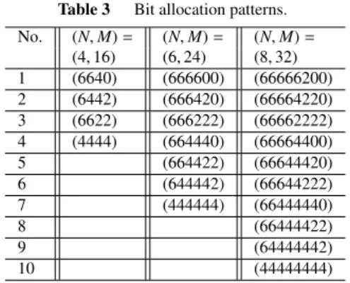
Table 2 summarizes the proposed adaptive bit alloca- tion, which requires the information about the MIMO chan- nel matrix, H, and the total number of bits,M. We list the bit allocation patterns utilized for our scheme in Table 3, where a combination ofNandMis denoted by (N,M), and (m1m2. . .mN) represents the number of bits in each sub- stream. In Table 3, all the possible bit allocation patterns subject tom1≥m2≥ · · · ≥mNare listed for a given (N,M).
In the first step of the adaptive bit allocation, we de- compose H into the matrices G, B and E by using the MSQRD. We then calculatePb by using Eq. (10) over the entire bit allocation patterns in Table 3 for a given (N,M) in the second step. In Eq. (12),γin thei-th substream is given by Eq. (9). In the third step, we determine a bit allocation pattern that minimizesPb, and we transmit a signal vector
Table 3 Bit allocation patterns.
No. (N,M)= (N,M)= (N,M)= (4,16) (6,24) (8,32) 1 (6640) (666600) (66666200) 2 (6442) (666420) (66664220) 3 (6622) (666222) (66662222) 4 (4444) (664440) (66664400)
5 (664422) (66644420)
6 (644442) (66644222)
7 (444444) (66444440)
8 (66444422)
9 (64444442)
10 (44444444)
Table 4 Computational complexity in the second step.
Calculations of Eq. (12) Summations in Eq. (10)
3N LN
24 (N=8) 80 (N=8,L=10)
based on the determined bit allocation pattern in the final step.
Now let us evaluate the computational complexity of the scheme in Table 2. In the first step, the MSQRD re- quires about 2N3flops, which is much less than 22N3flops for SVD[5]in E-SDM. In the second step, we calculate the average BER in Eq. (10) over all the bit allocation patterns, L, whereLdenotes the maximum number of the bit alloca- tion patterns. To execute this process, we need first to calcu- late the upper-bound of the BER in Eq. (12) for three modu- lation schemes defined in Table 1, and for given SNR in the i-th substream,γi, wherei=1,2,· · ·,N. Equation (12) con- sists of one real division, the calculation of the exponential function and one real multiplication. The total number of Eq. (12) to be calculated is given by 3N. The number is inde- pendent of the maximum number of bit allocation patterns, L. Next, we have to calculate the average BER in Eq. (10) for all the bit allocation patterns. The total number of the summations required for calculating all the average BER is LN. Multiplying the integer valuemiin Eq. (10) can be in- corporated into αi in Eq. (12), then we can ignore its cost.
The result of the complexity analysis is shown in Table 4.
We also show the values when N = 8 andL = 10. Since the MSQRD and SVD require respectively about 1024 and 11264 flops for its execution when N =8, we can say that the computational complexity of the second step is much lower than that of the decomposition algorithms. Regarding the third and fourth steps, we except them from the analysis since their complexity is obviously negligible.
4. Numerical Examples
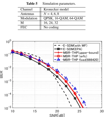
We demonstrate some numerical examples to evaluate the proposed adaptive bit allocation. The simulation parameters are listed in Table 5. The MIMO channel model is based on the Kronecker model[14].
Figure 2 shows BER curves of E-SDM and the MBR- THP as a function of SNR. We assume uncorrelated MIMO channel, where the correlation factorsρtandρrfor the trans-
Table 5 Simulation parameters.
Channel Kronecker model Antennas N=4,6,8
Modulation QPSK, 16-QAM, 64-QAM
M 16, 24, 32
FEC No coding
Fig. 2 BER curves when (N,M)=(6,24).
mitter and the receiver sides are zero. Two cases are demon- strated for E-SDM. In one case, we apply the power allo- cation using the WF, and in the other case, we do the equal power allocation (labeled as EPA in the figure). The upper- bound in Eq. (12) is applied to calculate average BERs for the adaptive bit allocation. For the MBR-THP, the cases of using Eq. (11) and Eq. (12) for the average BER calculation are demonstrated. A BER curve with the fixed bit allocation is also shown for the reference, where we take (666420) as the bit allocation pattern since it has shown the best BER performance when (N,M)=(6,24)[8].
We can see first that applying the adaptive bit allocation to the MBR-THP leads to the performance improvement.
As for the MBR-THP with the adaptive bit allocation, the difference in the BER calculation gives no impact. E-SDM with the power allocation using the WF shows the best BER performance. E-SDM with EPA is degraded by 1.5 dB from the best BER curve at the BER of 10−4, where the MBR- THP with adaptive bit allocation is degraded by about 0.7 dB from the BER of E-SDM with EPA.
In Fig. 3, we compare E-SDM and the MBR-THP when uncorrelated and correlated channels are applied. The cor- relation factors areρt =ρr =0.7 for the correlated channel.
The upper-bound in Eq. (12) is used for the adaptive bit al- location in all the schemes. The BER performance degrades in correlated MIMO channels regardless of the precoding scheme since the channel condition tends to be poor. When we compare the performance of the precoding schemes, E- SDM with optimum power allocation by using the WF out- performs the other cases. E-SDM with EPA outperforms the MBR-THP by about 1 dB at the BER of 10−4 when (N,M) = (8,32) in the uncorrelated channel case, but the
Fig. 3 BER curves with uncorrelated and correlated channels.
difference decreases when (N,M) = (4,16). On the other hand, in the correlated channel case with EPA, E-SDM and the MBR-THP show almost the same BER performance. In the correlated channel condition, MIMO channel matrices tend to be ill-conditioned with high probability. This means that, in E-SDM, the SNR in the first substream tends to be extremely higher than that of the other substreams. The SNRs of the substreams except for the first substream are then degraded significantly so that they are almost equiva- lent to that of the MBR-THP. As shown in Fig. 3, the dif- ference of the BER performance between two schemes can be small since the BER performance is dominated by these degraded substreams.
These results show that the MBR-THP is comparable with E-SDM in the BER performance if the equal power allocation is adopted.
5. Conclusions
The adaptive bit allocation for the MBR-THP has been pro- posed. The number of bits in each substream was de- termined adaptively so as to minimize the average BER.
The numerical examples demonstrated that the BER perfor- mance was improved by using the proposed bit allocation in comparison to the fixed bit allocation. In addition, the pro- posed method achieved comparable BER performance with E-SDM if an equal power is allocated in the correlated chan- nel.
References
[1] T. Ohgane, T. Nishimura, and Y. Ogawa, “Applications of space di- vision multiplexing and those performance in a MIMO channel,”
IEICE Trans. Commun., vol.E88-B, no.5, pp.1843–1851, May 2005.
[2] E. Biglieri, R. Calderbank, A. Constantinides, A. Goldsmith, A.
Paulraj, and H.V. Poor, MIMO Wireless Communications, Cam- bridge University Press, Cambridge, 2007.
[3] K. Miyashita, T. Nishimura, T. Ohgane, Y. Ogawa, Y. Takatori, and K. Cho, “High data-rate transmission with eignbeam-space division multiplexing (E-SDM) in a MIMO channel,” Proc. IEEE 56th Ve- hicular Tech. Conf., vol.3, pp.1302–1306, Vancouver, Canada, Sept.
2002.
[4] K. Ban, M. Katayama, T. Yamazato, and A. Ogawa, “Joint optimiza- tion of transmitter/receiver with multiple transmit/receive antennas in band-limited channels,” IEICE Trans. Commun., vol.E83-B, no.8, pp.1697–1704, Aug. 2000.
[5] G.H. Golub and C.F.V. Loan, Matrix Computations, The Johns Hop- kins University Press, Baltimore, 1996.
[6] C. Windpassinger, R.F.H. Fischer, T. Vencel, and J.B. Huber, “Pre- coding in multi-antenna and multiuser communications,” IEEE Trans. Wireless Commun., vol.3, no.4, pp.1305–1316, July 2004.
[7] S. Kinjo and S. Ohno, “Tomlinson-Harashima precoding with sub- stream permutations based on the bit rate maximization for single- user MIMO systems,” IEICE Trans. Fundamentals, vol.E98-A, no.5, pp.1095–1104, May 2015.
[8] S. Kinjo and S. Ohno, “A new mltiuser MIMO system with sum-rate maximization,” IEICE Commun. Express, vol.7, no.8, pp.297–302, Aug. 2018.
[9] L. Cao and S. Denno, “Nonlinear precoding for XOR physical layer network coding in bi-directional MIMO relay systems,” IEICE Trans. Commun., vol.E100-B, no.3, pp.440–448, March 2017.
[10] Y. Shinbo, N. Hiruma, and F. Maehara, “Performance evaluation of MU-MIMO THP with user scheduling in terms of system capacity and fairness,” IEEE International Symposium on Antenna and Prop- agation, pp.1–2, Phuket, Thailand, Oct. 2017.
[11] M. Payaro, A. Perez-Neira, and M.A. Lagunas, “Achievable rates for generalized spatial Tomlinson-Harashima precoding in MIMO systems,” Proc. IEEE 60th Vehicular Tech. Conf., pp.2462–2466, Los Angeles, U.S.A., Sept. 2004
[12] T. Yoo and A. Goldsmith, “On the optimality of multiantenna broad- cast scheduling using zero-forcing beamforming,” IEEE J. Sel. Ar- eas Commun., vol.24, no.3, pp.528–541, March 2006.
[13] R.F.H. Fischer, Precoding and Signal Shaping for Digital Transmis- sion, Wiley-Interscience, New York, 2002.
[14] K. Yu, M. Bengtsson, B. Ottersten, D. McNamara, P. Karlsson, and M. Beach, “Modeling of wide-band MIMO radio channels based on the NLoS indoor measurements,” IEEE Trans. Veh. Technol., vol.53, no.3, pp.655–665, May 2004.