INVITED PAPER
Special Section on Electronic DisplaysLow Power Consumption Technology for Ultra-High Resolution Mobile Display by Using RGBW System
Akira SAKAIGAWA†a), Masaaki KABE†, Tsutomu HARADA†, Fumitaka GOTO†, Naoyuki TAKASAKI†, Masashi MITSUI†, Tae NAKAHARA†, Kojiro IKEDA†, Kenta SEKI†, Toshiyuki NAGATSUMA†, andAmane HIGASHI†,Nonmembers
SUMMARY Battery life and outdoor visibility are two of the most im- portant features for mobile applications today. It is desirable to achieve both low power consumption and excellent outdoor visibility on the dis- play device at the same time. We have previously reported a new RGBW method to realize low power consumption and high luminance with high image quality. In this paper, the basic concept of a new RGBW calculation utilizing an “Extended HSV color space” model is described, and also its performance, such as low power consumption, color image reproducibil- ity and outdoor visibility is presented. The new method focuses on the luminance-increase ratio by means of a White signal for the display im- age data, and derives the appropriate RGBW signal and backlight PWM signal for every frame period. This dynamically controlled system solves the problems of conventional RGBW systems, and realizes the same image quality as a corresponding RGB display. In order to quantify its color image reproducibility, a spectroscopic measurement has been completed using the Macbeth Color Chart. In addition, the advantages of high luminance by the new RGBW method is described. The converted tone curve with an RGBW method provides very high luminance, such as 1,000 cd/m2, and improved outdoor visibility. Finally, a newly developed 4.38-inch full-HD (1,080× 1,920) 503 ppi prototype LCD utilizing this new RGBW technology is de- scribed.
key words: low power consumption, ultra-high resolution, LCD, mobile display, RGBW
1. Introduction
In recent years, mobile displays for Smartphone and tablet PC applications have become larger in size and higher in resolution. For example, smartphone resolution has dras- tically increased from qHD (540×960 pixels) to 720HD (720×1,280 pixels). Full-HD (1,080×1,920 pixels) was launched into the market earlier this year. Tablet PC dis- plays are also moving towards higher resolution than full- HD, such as WQXGA (1,600×2,560 pixels). Surprisingly, pixel density is approaching 400 ppi and more. As a result, the display power consumption continues to increase and it has a significant impact on the battery life of the mobile products [1].
For mobile display applications it is important to con- sider the display visibility in bright sunlight environments.
Very high luminance, such as 1,000 cd/m2, is required for a display to perform well in direct sunlight environments.
As a result, the power consumption, especially the backlight portion continues to increase. Therefore, a solution combing
Manuscript received March 3, 2013.
Manuscript revised June 10, 2013.
†The authors are with Japan Display Inc., Ebina-shi, 243-0432 Japan.
a) E-mail: [email protected] DOI: 10.1587/transele.E96.C.1367
both low power consumption and high luminance is urgently needed.
The RGBW pixel arrangement is one of the promising solutions for low power and high luminance [2]–[8]. Several RGBW products have already been launched into the mar- ket. However, conventional RGBW technology has image quality problems, such as a color purity degradation caused by both the signal processing itself and the optical illusion called “Simultaneous Contrast” [3]. We have previously re- ported a new RGBW system to solve the above problems [9]–[14]. We have also previously reported an outdoor visi- bility improvement using this RGBW system [10], [12].
In this paper, we will describe the performance of the new RGBW system, such as low power consumption, out- door visibility and color image reproducibility by using the Macbeth color chart. In addition, a newly developed 4.38- inch full-HD (1,080×1,920) 503 ppi prototype LCD utiliz- ing this new RGBW technology is described.
2. New RGBW Method
The conversion method from an RGB to an RGBW signal is widely known as Eq. (1). Here (Ri, Gi, Bi) and (Ro, Go, Bo) are digital values of the input and the output data, re- spectively. The White signal is extracted as the minimum value of the input RGB data.
Wo =min(Ri,Gi,Bi) (1)
The calculations are performed on the pixel data for the en- tire display. Usually, for example, for the sRGB color gamut case, the luminance of the White sub-pixel is twice as high as the RGB pixels, because the White sub-pixel has no color filter. As a result, less backlight power consumption is re- quired to maintain the original image luminance.
However, a pixel-by-pixel calculation using Eq. (1) provides luminance enhancement disparity over the screen, because the luminance-increase ratio for each pixel is differ- ent and depends on the image data.
For example as shown in Fig. 1, the minimum RGB portion can be replaced by White for the Color 1 area, whereas there is no White component for the Color 2 area which is a saturated color signal. The image deterioration by this luminance disparity has been reported previously [3].
Therefore, the luminance-increase ratio must be con- sidered for the RGBW conversion for each display image.
We have developed a new RGBW method, based on an Copyright c2013 The Institute of Electronics, Information and Communication Engineers
Fig. 1 Yellow window in the white background.
Fig. 2 Extended HSV color space.
extended HSV color space model [9]. This new RGBW method provides a simple way to determine the output White (Wo) and RGB data (Ro, Go, Bo) with an appropriate PWM value for the LED backlight.
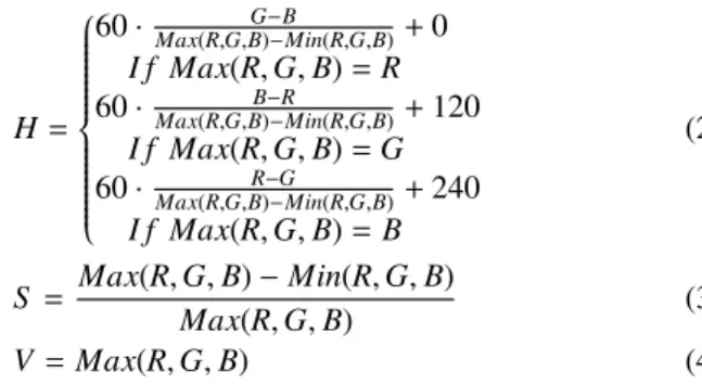
The extended HSV color space, as shown in Fig. 2, rep- resents the color and luminance capacity of the RGBW dis- play. The luminance data is plotted via the vertical axis as the V value, the saturation data is plotted via the horizon- tal axis as the S value and the various colors are plotted via the hue angle as the H value. The H, S and V values are calculated using Eqs. (2), (3) and (4).
H=
⎧⎪⎪⎪⎪⎪⎪⎪
⎪⎪⎪⎪⎨
⎪⎪⎪⎪⎪
⎪⎪⎪⎪⎪
⎪⎩
60· Max(R,G,B)G−−BMin(R,G,B)+0 I f Max(R,G,B)=R 60· Max(R,G,B)−B−RMin(R,G,B)+120
I f Max(R,G,B)=G 60· Max(R,G,B)−R−GMin(R,G,B)+240
I f Max(R,G,B)=B
(2)
S = Max(R,G,B)−Min(R,G,B)
Max(R,G,B) (3)
V=Max(R,G,B) (4)
By using this HSV color space, we can easily understand that the White sub-pixel approach can be used effectively for the low saturation area, whereas it cannot be used for the high saturation area. As we have reported previously, the brightness value of the low saturation area is expanded by using the White sub-pixel approach, as shown in Fig. 2.
This is different from the conventional cylindrical-shaped HSV color space. We call it the “Extended HSV Color Space” for RGBW displays. We can easily estimate the lu- minance of the RGBW display by using the “Extended HSV color space”. Here, K is the ratio of the luminance of the White sub-pixel and that of the RGB sub-pixels as shown in Eq. (5). The RGBW display is potentially (1+K) times
higher luminance than the RGB display.
k= Luminance of W pixel
Luminance of RGB pixels (5) If we consider the full-white image case, the backlight lumi- nance level is reduced by the inverse of 1+K. The original luminance level is maintained by this calculation.
If we consider images containing saturated colors, we can estimate the luminance-increase ratio by means of the White signal which is the function of the saturation of the in- put RGB data. Therefore, the maximum luminance-increase ratio (LIR) Zmaxvalue is defined as Eq. (6).
Zmax=1+k (0≤S ≤S i)
Zmax= f(S) (S i≤S ≤1) (6) S is the saturation value of the input data. Si is the inflection point on the Extended HSV color space as shown in Fig. 2.
This calculation is performed for each input image, and then the optimized RGBW signal and the optimized backlight level are determined as a PWM value by Eq. (7).
Backlight Level= 1
Z (7)
Since only one LIR value is calculated for the input image data, luminance enhancement disparity does not exist over the screen. For example, the relative luminance between chromatic and achromatic color is maintained in the RGBW output image. Therefore, color degradation, such as “Simul- taneous Contrast”, does not occur in this method. Addition- ally, the backlight level is simply determined as the inverse value of LIR. The output luminance is calculated to main- tain the original luminance of the input image. This cal- culation is performed every frame period, and then the opti- mized RGBW signal and the backlight level are dynamically controlled in a circuit block as reported previously [9]–[14].
Since the calculation circuits are built into the LCD driver ICs, the data and the command interfaces are the same as a conventional RGB-type LCD.
3. Performances of New RGBW Displays
3.1 Backlight Low Power Consumption
Table 1 shows the actual LIR value and the backlight power- saving ratio (%) for several images. Some of them are arti- ficial images such as a map, Macbeth Color Chart and color bars. For these images, the backlight power-saving ratio is small since the image is primarily composed of saturated colors.
On the other hand, for natural images, such as pho- tographs, this new RGBW approach aggressively reduces power consumption. In general, since photographs taken by a digital still camera have very few maximum lightness val- ues, the LIR becomes higher and the backlight power-saving ratio becomes bigger.
We have also obtained significant results in the evalua- tion of several video images such as movie, TV and gaming.
Table 1 Luminance-increase ratio (LIR) and backlight power-saving ratio results.
Movie images, especially, were found to have a significant power reduction, because they generally have low lightness and low saturation image data. In any case, very little dete- rioration has been observed in the RGBW picture quality by comparing it side-by-side with a reference RGB display.
A quantitative comparison has been completed by mea- suring the color reproducibility as described in the following section.
3.2 Evaluation of Color Image Reproducibility
In order to verify the image quality of a new RGBW dis- play, we have measured the color reproducibility by using a Macbeth Color Chart.
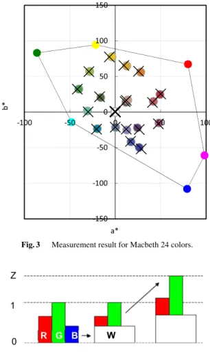
The measurement has been done by using RGB data for Macbeth 24 colors with the conditions of D65 illumi- nant and 2-degree Standard Observer [15]. This RGBW display has sRGB color gamut with D65 White point and 2.2-gamma. Figure 3 shows the measurement result of a*- b* values for the Macbeth 24 Colors of a new RGBW dis- play, comparing it to the sRGB standard value. Most of the color difference (ΔEab*) between the RGBW and the sRGB
Fig. 3 Measurement result for Macbeth 24 colors.
Fig. 4 Luminance improvement method using RGBW. (a) RGB. (b) Conventional RGBW. (c) Luminance enhancement using new RGB (x Z).
standard values were smaller than 3. As this result shows the new RGBW display has excellent color reproducibility and it is compatible to a conventional RGB display which has sRGB color gamut.
3.3 Improvement of Outdoor Visibility
We have developed the method to improve outdoor visibility by using the new RGBW technology with a converted tone curve [10]. When the digital values for input signals are (Ri, Gi, Bi) and the level of the luminancei-increase ratio is Z, the output signals (Ro, Go, Bo, Wo) are defined by Eq. (8). The difference between conventional method and new method is shown in Fig. 4.
In this case, the output luminance is enhanced by the value Z when the backlight control is turned off. As we reported in a former paper [10], [12], the RGBW dis- play potentially has two times higher luminance, such as 1,000 cd/m2.
Fig. 5 Tone curve for the dynamic range correction.
Ro=Z×Ri−Wo
Go=Z×Gi−Wo
Bo=Z×Bi−Wo
Wo=min(Ri,Gi,Bi)
(8)
In addition, we have developed a new method, Dynamic Range Correction (DRC), to modify the tone curve as shown in Fig. 5 and enhance the luminance of displayed images [10]. This tone curve correction method can enhance the gray scale luminance.
The outdoor visibility improvement was confirmed by combining the luminance enhancement of the display utiliz- ing the new RGBW technology and the tone curve correc- tion method. We call this “Outdoor mode”.
4. Ultra-High Resolution LCD by Using RGBW Sys- tem
Finally, we will describe the capability of the new RGBW technology for an ultra-high resolution mobile display.
In general, the sub-pixel aperture ratio is dramatically reduced as the pixel density (PPI, pixel per inch) increases.
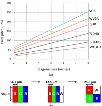
The backlight power consumption also increases and the lu- minance of the LCD module is limited by both electrical and mechanical reasons. We also need to take into account that the pixel density is limited by the horizontal sub-pixel length in the RGB stripe pixel arrangement which uses a vertical rectangle sub-pixel shape. Figure 6(a) shows the pixel pitch versus display diagonal size for several resolu- tions. Displays of 500 ppi, such as 4.5-inch full-HD or 6- inch WQXGA, have 50µm pixel pitches. In this case, the sub-pixel pitch of 12.5µm is too small to make a RGBW stripe pixel arrangement. The four square sub-pixel arrange- ment is useful for this purpose, because the sub-pixel pitch become 25µm. (see Fig. 6(b)).
In this paper, we propose an arrangement of RGBW square sub-pixels to realize an ultra-high resolution 503 ppi display as shown in Table 2. Since the 4.38-inch full-HD (1920×1080) RGBW panel has 25.5µm×25.5µm square sub-pixels, high aperture ratio and high transmittance, com- patible to lower resolution products has been achieved. The backlight of this ultra-high resolution LCD utilizing new RGBW method realized 40% less power consumption as
(a)
(b)
Fig. 6 (a) Pixel density versus display diagonal size.(b) Sub-pixel arrangement for 500 ppi.
Table 2 Ultra-high resolution LCD with RGBW system.
compared to that of conventional RGB display module. It is estimated that the conventional RGB display with the same diagonal size consumes 500 mW on its backlight portion to achieve the luminance at 350 cd/m2.
It was also confirmed that the display’s outdoor visi- bility was improved, through both high luminance and con- verted tone curve as described above. The luminance at the Outdoor mode was 67% higher than that of conventional RGB display with the same backlight power.
Figure 7(a) shows a photograph of the prototype 4.38-inch full-HD LCD with the new RGBW system and Fig. 7(b) shows its magnified image. Since the pixel dots and jagged edges are not perceived at this pixel density, the picture quality approaches that of film photography.
(a)
(b)
Fig. 7 (a) A photo of the prototype 4.38-inch full-HD LCD with RGBW system. (b) A magnified picture of the prototype 4.38-inch full-HD LCD with RGBW system.
5. Conclusion
The new RGBW technology has been successfully devel- oped to save backlight power consumption while maintain- ing image quality. The power saving ratio of backlight was 40% in average at natural images such as photographs.
The RGBW square sub-pixel arrangement utilizing this new RGBW technology realizes ultra-high resolution over 500 ppi and solves the power consumption issues.
References
[1] A. Caroll and G. Heiser, “An analysis of power consumption in a smartphone,” Proc. USENIX Annual Technical Conference, pp.271–284, Boston MA, USA, June 2010.
[2] B.-W. Lee, “TFT-LCD with RGBW color system,” SID Symposium Digest of Technical Papers, vol.34, no.1, pp.1212–1215, May 2003.
[3] B.-W. Lee, K. Song, Y. Yang, C. Park, J. Oh, C. Chai, J. Choi, N.
Roh, M. Hong, K. Chung, S. Lee, and C. Kim, “Implementation of RGBW color system in TFT-LCDs,” SID Symposium Digest of Technical Papers, vol.35, no.1, pp.111–113, May 2004.
[4] H.J. Yoon, J.H. Lee, K.P. Hong, J.Y. Chun, B.Y. Ryu, J.M. Jun, and J.Y. Lee, “Development of the RGBW TFT-LCD with data render- ing innovation matrix (SRIM),” SID Symposium Digest of Technical Papers, vol.36, no.1, pp.244–247, May 2005.
[5] C.Y. Tsai, Y.C. Tsai, Y.J. Chang, W.C. Chang, and D.L.P. Ting, “Ad- vanced transmissive-LCDs with high reflectance in RGBW,” Proc.
13th International Display Workshops, pp.809–810, Dec. 2006.
[6] C.F. Hsu, C.-C. Lai, and J.-S. Li, “A modified stripe-RGBW TFT-
LCD with image-processing engine for mobile phone displays,”
Proc. 14th International Display Workshops, pp.2317–2320, Dec.
2007.
[7] L. Wang, Y. Tu, L. Chen, K. Teunissen, and I. Heynderickx, “Trade- offbetween luminance and color in RGBW displays for mobile- phone usage,” SID Symposium Digest of Technical Papers, vol.38, no.1, pp.1142–1145, May 2007.
[8] C.H.B. Eliot, M.F. Higgins, S. Hwang, S.J. Han, A. Botzas, B.-S.
Hsu, M. Im, and S. Nishimura, “PenTile RGBW color processing,”
SID Symposium Digest of Technical Papers, vol.39, no.1, pp.1112–
1115, May 2008.
[9] A. Sakaigawa, M. Kabe, Y. Matsui, T. Nagatsuma, and A. Higashi,
“Development of high image quality with low power consumption mobile display by using novel RGBW technology,” Proc. 31st Inter- national Display Research Conference (Eurodisplay), pp.188–191, Sept. 2011.
[10] A. Higashi, T. Nagatsuma, M. Kabe, Y. Matsui, and A. Sakaigawa,
“A method of improving display visibility under the bright envi- ronment,” Proc. 18th International Display Workshops, pp.349–351, Dec. 2011.
[11] A. Sakaigawa, “Low power consumption technology for TFT-LCD by using RGBW pixel arrangement,” Gekkan Display, vol.18, no.7, pp.82–87, Techno Times, 2012.
[12] K. Ikeda, A. Sakaigawa, M. Kabe, T. Harada, F. Goto, T. Nakahara, K. Yagiura, and C. Tanaka, “RGBW display technology for auto- motive application,” Proc. 19th Annual Symposium on Vehicle Dis- plays, MI, USA, 3-1, Oct. 2012.
[13] A. Sakaigawa, M. Kabe, T. Harada, F. Goto, N. Takasaki, M. Mitsui, T. Nakahara, K. Ikeda, K. Seki, T. Nagatsuma, and A. Higashi,
“Low power consumption technology for ultra-high resolution mo- bile display by using RGBW system,” Proc. 19th International Dis- play Workshops, pp.709–712, Dec. 2012.
[14] T. Nakahara, A. Sakaigawa, M. Okita, K. Ikeda, M. Mitsui, M. Kabe, T. Nagatsuma, and A. Higashi, “Image quality assessment of ultra- high resolution mobile display utilizing new RGBW method,” SID Symposium Digest of Technical Papers, vol.44, pp.955–958, May 2013.
[15] D. Pascale, “RGB coordinates of the macbeth colorchecker,”
http://www.babelcolor.com/main level/ColorChecker.htm # Color Checker data
Akira Sakaigawa received his Ph.D. de- grees in Material Science from Saitama Univer- sity Graduate School of Science & Engineering in 1994. He has extensive experience in the field of Liquid Crystal Display technology develop- ment. He is currently Senior Technical Special- ist at Japan Display Inc., Display System R&D department and a team leader of RGBW tech- nology development.
Masaaki Kabe received his M.Sc. degrees in Organic and Polymeric Materials from Tokyo Institute of Technology Graduate School of Sci- ence and Engineering in 1995. His research in- terests include optical design of Liquid Crystal Display. He is currently Technical Specialist at Japan Display Inc. Display System R&D de- partment and RGBW technology development team.
Tsutomu Harada received his M.E. de- grees in Applied Physics from Waseda Univer- sity Graduate School of Science & Technology in 1992. His research interests include digital signal processing for servo technology and im- age processing. He is currently Technical Spe- cialist at Japan Display Inc., Display System R&D dept. and co-leader of RGBW technology development team.
Fumitaka Goto received his B.E. degrees in Electronics from Tokyo Denki University of Engineering in 2007. He has extensive experi- ence in the design of electronic circuit. He is currently System Engineer at Japan Display Inc.
Display System R&D department and a member of RGBW technology development team.
Naoyuki Takasaki received his M.E. de- grees in Materials Science & Engineering from Nagoya University Graduate School of Mate- rials, Physics & Energy Engineering in 2006.
He has extensive experience in the field of Ma- terials and Processing technology development.
He is currently electrical engineer at Japan Dis- play Inc. Display System R&D department and a member of RGBW technology development team.
Masashi Mitsui received his B.E. degrees in Electronic Engineering from Tohoku Univer- sity, Faculty of Engineering in 1999. He has ex- tensive experience in the field of Liquid Crystal Display technology development. He is Optical Design Engineer at Japan Display Inc., Display System R&D department
Tae Nakahara received her M.Sc. degrees in Applied Chemistry from Kyushu Institute of Technology University Graduate School of En- gineering in 2004. She is associate Technical Specialist at Japan Display Inc. Display Sys- tem R&D department. She has been engaged in panel design development for many years and currently she is a member of RGBW technology development team.
Kojiro Ikeda received his M.E. degrees in Physical Chemistry from Tokyo Institute of Technology Graduate School of Science & En- gineering in 2005. He has extensive experience in the optics of Liquid Crystal Display technol- ogy development. He is currently engineer at Japan Display Inc. Display System R&D de- partment and a member of RGBW technology development team.
Kenta Seki received his M.Sc. degrees in Material Science from Keio University Gradu- ate School of Science & Technology in 2007.
He has extensive experience in the application of the magnetic materials. He is currently Opti- cal Design Engineer at Japan Display Inc. Panel Design Department and developing in the Liq- uid Crystal Materials.
Toshiyuki Nagatsuma received his B.E.
degrees in Electronics from Tokyo University of Science in 1999. He has extensive experience in the design of driver IC. He is currently System Engineer at Japan Display Inc. Display, Mobile Product Design Dept., Driver IC Design Group and a member of RGBW technology develop- ment team.
Amane Higashi received his M.Sc. degrees in Material Science from Hiroshima University Graduate School of Advanced Sciences of Mat- ter in 2002. He has extensive experience in the software development for the optical simulation and image processing. He is currently Associate Technical Specialist at Japan Display Inc. Panel Design Department., Design Platform group.