Switching Effect of Synchronization Phenomena in Ladder-Coupled Chaotic Network
Including Ring Structure
Katsuya Nakabai, Yoko Uwate and Yoshifumi Nishio Dept. of Electrical and Electronic Engineering, Tokushima University
2-1 Minami-Josanjima, Tokushima 770–8506, Japan Email:{nakabai, uwate, nishio}@ee.tokushima-u.ac.jp
Abstract—In this study, we investigate synchronization phe- nomena in coupled chaotic network including one ladder and five ring structures. We set the bifurcation parameter of the circuits to generate periodic solutions or chaotic solutions. The ladder position is chaotic state and five ring positions are stable state.
By the computer simulations, we confirm that synchronization state is switching in the model by changing bifurcation parameter.
I. INTRODUCTION
Synchronization in the network is one of the most inter- esting fields from the scientific points. Investigation of the synchronization is an important research for clarifying the nonlinear phenomenon in the natural world, which has been observed in various fields such as engineering, biology, and sociology. The network also has characteristics with different topologies. Therefore, it is important to investigate the dynam- ics due to the difference in network structure, and research to analyze each topology is underway [1]-[5].
On the other hand, synchronization in coupled chaotic systems is a suitable model for describing various high- dimensional nonlinear phenomena. Especially, in recent years, many studies of chaotic phenomena using coupled chaotic circuits have been conducted. Circuit experiments and com- puter simulations of chaotic circuits with simple configurations are considered to be suitable due to their high reproducibil- ity. Investigation of nonlinear phenomena related to chaotic phenomena will be an important issue in future engineering.
Networks using chaotic circuits are expected to be applied to modeling of the natural world and social networks [6],[7].
Previously, our research group investigated the synchroniza- tion phenomena observed in ladder coupled systems including ring structures. We confirmed perfect synchronization and chaotic synchronization in different network topologies [8]. In this study, we investigate the synchronization phenomena of a larger scale than the previous network model. We particularly focus on the bridge positions that connect the ladder and ring structures. Each coupled chaotic circuit sets parameters for generating a chaotic solution or a periodic solution. By computer simulation, we investigate the synchronization phe- nomenon in each part by changing the bifurcation parameter
in the chaotic network. We also observe the switching effect of synchronous stability in each part of the network.
II. NETWORK MODEL
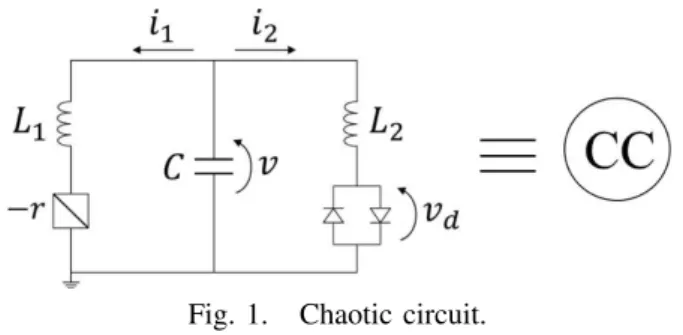
In this study, we use chaotic circuits. The model of chaotic circuit is shown in Fig. 1. This circuit consists of a negative resistor, two inductors, a capacitor and dual-directional diodes.
This chaotic circuit is called Nishio-Inaba circuit [9].
Fig. 1. Chaotic circuit.
First, the circuit equations of this circuit are described as
follows:
L1
di
dt =v+ri L2
di
dt =v−vd
Cdv
dt =−i1−i2.
(1)
The characteristic of nonlinear resistance is described as follows:
vd= rd
2
(i2+ V rd
− i2−V
rd )
. (2)
By changing the variables and parameters,
i1=
√C
L1V xn, i2=
√L1C
L2 V yn, v=V zn
α=r
√C L1
, β=L1 L2
, δ=rd
√L1C L2
, t=√
L1C2τ.
(3)
- 32 -
IEEE Workshop on Nonlinear Circuit Networks December 13-14, 2019
The normalized circuit equations are given as follows:
dxi
dτ =αx+z dyi
dτ =z−f(y) dzi
dτ =−x−βy.
(4)
f(yi)is described as follows:
f(yi) = 1 2
(yi+1 δ
− yi−1
δ )
. (5)
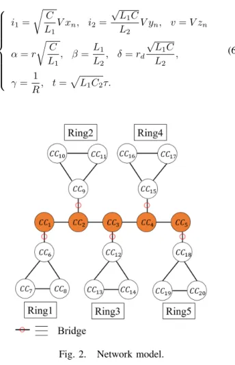
In this study, we propose a network model with ladder- coupled chaotic network including ring structure. Each chaotic circuit is coupled by resistor. Figure 2 shows the proposed network model.
We set the parameters that the ladder position composed of CC1 to CC5 generates a chaotic solution, and the five ring positions composed of CC6 to CC20 generate periodic solutions.
By changing the variables and parameters,
i1=
√C L1
V xn, i2=
√L1C L2
V yn, v=V zn
α=r
√C
L1, β= L1
L2, δ=rd
√L1C L2 , γ= 1
R, t=√ L1C2τ.
(6)
Fig. 2. Network model.
R is the resistor that couples each chaotic circuit.
The normalized circuit equations of the systems are given
as follows:
dxi
dτ =αxi+zi dyi
dτ =zi−f(y) dzi
dτ =−xi−βyi−
∑N i,j=1
γij(zi−zj) (i, j= 1,2,· · ·, N).
(7)
In Eq. (7), N means the number of coupling circuits, γ is the coupling strength between circuits, and α is a parameter indicating nonlinear degree. In this study, we set the parameters of the system as β = 3.0 andδ= 470.0. For the parameter α , the ladder part is set as α = 0.430 and the ring part is set as α = 0.412. The coupling strength γ is defined as a bifurcation parameter. The coupling strength at the ladder and ring positions is set as γ = 0.2. In this research, to investigation based on the combination of two topological types of ladder structure and ring structure, we simulate the synchronization by changing the positions of bridge that couple between the two structures (for example, the resistance that couples CC1 andCC6).
In this study, the periodic and chaotic solutions are judged by attractors. Figure 3 shows each attractor when parameters are set so that a three-period solution and a chaotic solution are generated.
zi
xi
zi
xi
(a) Three periodic attractor. (b) Chaotic attractor.
Fig. 3. Attractors.
III. SIMULATION RESULTS
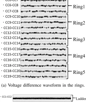
We investigate the synchronization state by the computer simulation. In this study, we simulate the synchronization of chaotic network by dividing the coupling strength of the bridge part into three patterns of γ = 0.01, γ = 0.1, and γ = 0.2.
Voltage difference waveform between each circuit is used as a method for confirming the synchronization state. When the voltage difference is small, it is considered that each circuit is performing the same output and synchronization is considered to occur. When the voltage difference is large, it is considered that each circuit outputs a different output and the state is regarded as asynchronous.
First, Fig. 4 shows the results when the value of coupling strength at the bridge isγ= 0.01, which is much weaker than other coupling strength. In this case, as shown in Fig. 4(a), we obtain the difference of each ring. As time advanced, the position of synchronization or asynchronous state changes to another place. On another front, Fig. 4(b) shows that the bridge position is constantly asynchronous. The state is initially asynchronous in Ring3, but we confirm that the asynchronous position moved to Ring1 and Ring5 over time. Subsequently,
- 33 -
the effect of switching the synchronization state on the rings is repeated.
Next, Fig. 5 shows the result when the value of coupling strength at the bridge is γ = 0.1. In this case, as shown in Fig. 5(a), it is confirmed that chaotic propagation from the ladder part to the ring part occur due to the stronger coupling strength than γ = 0.01. We obtain chaotic synchronization between all the rings in this situation. At the same time, we also confirm that the chaotic circuit in the ring where the three periodic attractor should occur become chaotic attractor due to the influence of chaotic propagation. Additionally, Fig. 5(b) shows that the state of bridge position becomes also the chaotic synchronization.
Finally, Fig. 6 shows the results when the value of coupling strength at the bridge isγ= 0.2. In this case, the connection between the ladder part and ring position become stronger, and the whole network was observed to be close to perfect synchronization again. However, unlike γ = 0.01, where perfect synchronization was observed earlier when γ = 0.2, the timing at which perfect synchronization occurs in each ring is a phenomenon in each part of the network. Taking Fig. 6 as an example, in the case of Ring1, a perfect synchronization state is initially observed betweenCC6andCC7, but the same is observed between CC6 and CC8 as advanced time. The state is switched, and when more time passed, it switches between CC7 and CC8, and this behavior is repeated. It is confirmed that the same behavior occur at each timing between the rings.
Based on these results, it is confirmed that the synchro- nization state at each location in the network switched by changing the coupling strength of the bridge location, which is a bifurcation parameter. However, regarding switching when γ = 0.01, we could not confirm the regularity of the order of the ring part where the asynchronous state changes in this study. When it is considered that the voltage difference propagates, in this result, it is thought that Ring2 and Ring4 that are adjacent to Ring3 would continue to be unstable, but the results are different, so further investigation is necessary.
(a) Time advancedτ= 50000−100000in the rings.
(b) Time advanced τ= 150000−200000in the rings.
(c) Time advancedτ = 50000−100000in ladder and bridge.
Fig. 4. Voltage difference waveform as the bridgeγ= 0.01.
(a) Voltage difference waveform in the rings.
(b) Voltage difference waveform near Ring1.
Fig. 5. Voltage difference waveform as the bridgeγ= 0.1.
- 34 -
(a) Voltage difference waveform in the rings.
(b) Voltage difference waveform near Ring1.
Fig. 6. Voltage difference waveform as the bridge γ= 0.2.
IV. CONCLUSIONS
In this study, we investigated the synchronization phe- nomenon in a network composed of coupled chaotic circuits.
The network topology is a ladder coupled system including a ring structure.
As a result of investigation by computer simulation, we ob- served synchronization states such as chaotic synchronization and perfect synchronization by changing the coupling strength of the bridge part. In the case ofγ= 0.01, the ladder position and ring position are asynchronous. However in the case of γ= 0.1 andγ = 0.2, coupling strength of bridge position is more stronger, and the the ladder position and ring position become synchronization.
Moreover, it was confirmed that the switching of the syn- chronized state occurs by increasing the coupling strength of the bridge. In the switching phenomenon, there is a difference that the phenomenon in the whole network or the phenomenon in one place in the network is seen due to the change of the branching parameter.
In our future works, we investigate the order of the position becoming asynchronous state in the case of γ = 0.01.
Furthermore, we analyze the dynamics of synchronization in more intricate networks.
REFERENCES
[1] P. M. Gade, “Synchronization in coupled map lattices with random nonlocal connectivity” Phys. Rev. E, vol. 54, no. 1, pp. 64-70, 1996.
[2] I. Belykh, M. Hasler, M. Lauret and H. Nijmeijer, “Synchronization and graph topology” Int. J. Bifurcation and Chaos, vol.15, no.11, pp.
3423-3433, Nov. 2005.
[3] D. Malagarriga, A. E. P. Villa, J. Garca-Ojalvo and A. J. Pons, “Con- sistency of heterogeneous synchronization patterns in complex weighted networks” Chaos 27, 031102, 2017.
[4] S. Boccaletti, V. Latora, Y. Moreno, M. Chavez and D.-U. Hwang,
“Complex networks: structure and dynamics.” Phys. Rep. 424, pp. 175- 308 2006.
[5] J. W. Wang and Y. B. Zhang, “Network synchronization in a population of star-coupled fractional nonlinear oscillators” Phys. Lett, A 374, pp.
1464-1468 2010.
[6] T. Nishiumi, Y. Uwate and Y. Nishio, “Synchronization Phenomena of Chaotic Circuits with Stochastically-Changed Network Topology”, Proceedings of International Symposium on Nonlinear Theory and its Applications (NOLTA’14), pp. 811-814, Sep. 2014.
[7] N. F. Rullckov and M. M. Sushchik, “Robustness of Synchronized Chaotic Oscillations” Int.J.Bifurcation and Chaos, vol. 7, no. 3, pp. 625- 643, 1997.
[8] K. Nakabai, Y. Uwate and Y. Nishio, “Synchronization in Ladder- Coupled Chaotic Circuits Including Ring Structure” Proceedings of IEEE International Symposium on Circuits and Systems (ISCAS’19), DOI:10.1109/ISCAS.2019.8702350, May 2019.
[9] Y. Nishio, N. Inaba, S. Mori and T. Saito, “Rigorous Analyses of Windows in a Symmetric Circuits” IEEE Transactions on Circuits and Systems“, vol. 37, no. 4, pp. 473-487, Apr. 1990.
- 35 -