Synchronization Phenomena of
Symmetric and Asymmetric Structures Using Coupled Chaotic Circuits
Katsuki Nakashima, Yoko Uwate and Yoshifumi Nishio Dept. of Electrical and Electronic Eng., Tokushima University
2-1 Minami-Josanjima, Tokushima 770–8506, Japan Email: { nakashima, uwate, nishio } @ee.tokushima-u.ac.jp
Abstract—Nonlinear phenomena of coupled chaotic circuits are drawing attention from many researchers. In this study, we investigate the synchronization phenomena of coupled two symmetrical structures and the influence of the network topology when we use chaotic circuits. One structure generates chaotic attractors and the other structure generates three-periodic at- tractors. Moreover, we observe the synchronization phenomena of networks with asymmetrical structures and we compare networks with symmetrical structures to networks with asymmetrical structures.
I. I NTRODUCTION
Synchronization phenomena have been found in various fields of natural world [1]-[3]. Especially, there are a lot of relationships of animate things. Also, synchronization phe- nomena have a relationship with the human body. For example, cells of the human body are synchronized. Therefore, the oscillation of same timing produces big oscillation. According to synchronization phenomena, small power produces very big power.
Recently, complex networks have attracted attention and topology of complex networks is studied for influence on the system [4], [5]. Also, synchronization phenomena of chaotic circuits are studied from various viewpoints. For example, it is studied in biology, engineering, medical science and so on. The oscillation that chaos occurs is the same as the oscillation of the natural world. In the chaotic circuit, a phenomenon by the name of chaotic synchronization has been confirmed. It has been applied to chaotic control, chaotic com- munication and so on. Before now, network topology attracts attention how to behave for coupled chaotic circuits because the investigation of the influence for network topology and application examples are less low. Currently, simple system has already been studied. For example, it is only ring structure, only ladder structure, only star structure and so on [6]-[8].
However, many researchers have not been studied about more complex systems. Therefore, we propose the coupled two symmetrical and asymmetrical structures of chaotic circuits and we investigate the influence of network topology.
In this study, we investigate the synchronization phenomena of networks with symmetrical and asymmetrical structures when we use chaotic circuits. First, we propose system mod- els that the two symmetrical structures are coupled via a
resistor. One structure generates chaotic attractors and the other structure generates three-periodic attractors. Moreover, we observe the synchronization phenomena of networks with asymmetrical structures and we compare networks with sym- metrical structures to networks with asymmetrical structures.
In addition, we focus on the synchronization rate of each model.
II. C IRCUIT MODEL
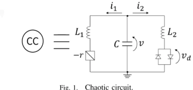
The chaotic circuit is shown in Fig. 1. This chaotic circuit is Nishio-Inaba circuit [9]. This chaotic circuit consists of two inductors L 1 and L 2 , one capacitor C , negative resistor − r and two diodes.
CC
Fig. 1. Chaotic circuit.
The circuit equations of chaotic circuits are given as follows:
L 1 di 1
dt = v + ri 1 , L 2 di 2
dt = v − v d , C dv
dt = − i 1 − i 2 .
(1)
The current-voltage characteristics of nonlinear resistor are given as follows:
v d = r d 2
( i 2 + V r d
− i 2 − V
r d
)
. (2)
By chaning the parameters as follows:
- 23 -
IEEE Workshop on Nonlinear Circuit Networks
December 7-8, 2018
i 1 =
√ C L 1
V x n , i 2 =
√ L 1 C L 2
V y n , v = V z n ,
α = r
√ C L 1
, β = L 1
L 2
, δ = r d
√ L 1 C L 2
,
γ = 1
R , t = √ L 1 C 2 τ.
(3)
The normalized equations of chaos circuits are given as follows:
dx i
dτ = αx i + z i , dy i
dτ = z i − f (y i ), dz i
dτ = − x i − βy i −
∑ N i,j=1
γ ij (z i − z j ), (i, j = 1, 2, · · · , N ).
(4)
Where γ is the coupling strength and f (y i ) is described as follows:
f (y i ) = 1 2
( y i + 1 δ
− y i − 1
δ )
. (5)
We define α c to generate the chaotic attractor and α p is defined to generate the three-periodic attractors. N is the number of coupled chaotic circuits. We use the attractor as shown in Fig. 2. For the computar simulation, we set the parameters of the system as α c = 0.460, α p = 0.412, β = 3.0 and δ = 470.0.
z z
x x
(a) Chaotic attractor. (b) Three-periodic attractor.
Fig. 2. Attractor.
III. S YSTEM MODELS
Figure 3 shows the proposed system models. We propose the system models that the two symmetrical structures are coupled by a resistor in Fig. 3(a) and (b). In addition, we propose the system models that the two asymmetric structures are coupled by a resistor in Fig. 3(a’) and (b’). In Fig. 3(a) and (a’), we set CC1 to CC4 as chaotic solution and CC5 to CC8 as three-periodic solutions. In Fig. 3(b) and (b’), we set CC1 to CC5 as chaotic solution and CC6 to CC10 as three- periodic solutions. In this study, we set the coupling strength γ as 0.2, the coupling strength γ 1 between the topologies as 0.1 and γ 2 as 0.01 in all models. The coupling strength γ and γ 2 are the synchronized value with a single structure.
γ γ
γ γ
γ γ
γ γ
γ γ
γ γ
γ γ γ
γ1 γ1
2 2
2
2 2
2 2
2
2 2
(a) 4-4 Coupled Model. (a') 1-4 Coupled Model.
γ1 γ1
γ
γ γ
γ γ
γ γ
γ γ
γ
γ γ γ
γ
γ γ
γ
γ γ
γ γ
2 2
2 2 2 2
2
2 2
2
2 2 2
2
(b) 5-5 Coupled Model. (b') 1-5 Coupled Model.
Fig. 3. System models.
IV. S IMULATION RESULTS
We investigate the synchronization phenomena in each model and the influence of topology. Figure 4 shows attractor of each chaotic circuit, Fig. 5 shows lissajous figure and Fig. 6 shows the volage of different waveform. CC5 to CC8 generate chaotic attractor in each model. Also, between CC4 and CC5 are synchronized. CC6-CC5, CC6-CC7 and CC6-CC8 are asynchronous. CC7-CC5 and CC7-CC8 are chaotic synchro- nization in model (a). Therefore, in CC7-CC5 and CC7-CC8, synchronous and asynchronous states changes irregularly in the simulation time.
1
1 2 3 4 5 6
2 3 4 5 6
z z z z z z
x x x x x x
7 8
7 8
z z
x x
(a) 4-4 Coupled Model.
4 5 6
4 5 6
z z z
x x x
7 8
7 8
z z
x x
(a’) 1-4 Coupled Model.
Fig. 4. Attractors.
2
1 2 4 2 3 4
4 1 3 4 5
z z z z z z
z z z z z z
5
5 7 5 8
7 6 8 7
6
z z z z
z z z z z
z
(a) 4-4 Coupled Model.
5
5 7 5 8
7 6 8 7
6
z z z z
z z z z z
z
4
5
z z
(a’) 1-4 Coupled Model.
Fig. 5. Lissajous figures.
- 24 -
z
1ー 2 2ーー 1 ー 3 ー 4 ー 5 ー 5
z z
z z z z z z
4z
2z
3z
4ー 7 ー 6 ー 8 ー 7
z
z z
5
z z z
8z
6z
5z
7z
4(a) 4-4 Coupled Model.
ー 5 ー
z
5z z
4ー 7 ー 6 ー 8 ー 7
z
z z
5
z z z
8z
6z
5z
7(a’) 1-4 Coupled Model.
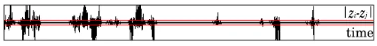
Fig. 6. Different waveform.
Figure 7 shows attractor of each chaotic circuit, Fig. 8 shows lissajous figure and Fig. 9 shows the volage of dif- ferent waveform. In both model (b) and model (b’), CC6 to CC10 generate chaotic attractor. Also, between CC5 and CC6 are synchronized. In model (b), CC6-CC7, CC6-CC8, CC6-CC9 and CC6-CC10 are asynchronous. CC7-CC8, CC8- CC9 and CC9-CC10 are chaotic synchronization. Therefore, in CC7-CC8, CC8-CC9 and CC9-CC10, synchronous and asynchronous states changes irregularly in the simulation time.
1
1 2 3 4 5 6
2 3 4 5 6
z z z z z z
x x x x x x
7 8
7 8
z z
x x
9
9
z x
10
10
z x (b) 5-5 Coupled Model.
6
6
z x
7 8
7 8
z z
x x
9
9
z x
10
10
z x
5
5
z x
(b’) 1-5 Coupled Model.
Fig. 7. Attractors.
2
1 2 5 2 3
5 1 3 5
z z z z z
z z z z z
3
4
z z
4
5
z z
5
6
z z
10
8
z
8
z
8 6 6 9
7 9 10 10
6
z z z z
z z z z z
z
7
6
z z
(b) 5-5 Coupled Model.
10
8
z
8
z
8 6 6 9
7 9 10 10
6
z z z z
z z z z z
z
7
6
z z
5
6
z z
(b’) 1-5 Coupled Model.
Fig. 8. Lissajous figures.
z
1ー 2 2ー 5 ー 1 ー 3 ー 5 ー 4 ー 5z z
z z z z z z z
5z
2z
3z
3ー 6 ー 6 ー 8 ー 7
z
z z z z
6z
8z
4z
5z
7ー 10 ー 10 ー
z
8z z z
9z
10z
6 ーz
9z
6(b) 5-5 Coupled Model.
ー 6 ー 6 ー 8 ー 7
z
z z
6
z z z
8z
5z
7ー 10 ー 10 ー