JAIST Repository
https://dspace.jaist.ac.jp/
Title UMLステートチャートに対するモデル検査に関する研究
Author(s) 林, 信宏
Citation
Issue Date 2003‑09
Type Thesis or Dissertation Text version author
URL http://hdl.handle.net/10119/1765 Rights
Description Supervisor:片山 卓也, 情報科学研究科, 修士
A Research of Model Checking UML Statechart Diagrams
By Lin Hsin-Hung
A thesis submitted to School of Information Science,
Japan Advanced Institute of Science and Technology, in partial fulfillment of the requirements
for the degree of
Master of Information Science
Graduate Program in Information Science
September, 2003
A Research of Model Checking UML Statechart Diagrams
By Lin Hsin-Hung (110205)
A thesis submitted to School of Information Science,
Japan Advanced Institute of Science and Technology, in partial fulfillment of the requirements
for the degree of
Master of Information Science
Graduate Program in Information Science
Written under the direction of Professor Takuya Katayama
and approved by
Professor Takuya Katayama Professor Koichiro Ochimizu Professor Kokichi Futatsugi
August, 2003 (Submitted)
Copyright c2003 by Lin Hsin-Hung
Abstract
In this research, we design an algorithm to translate UML statechart diagrams into SMV code, then apply CTL model checking to verify UML statechart diagrams. Our algorithm is mainly based on STP-approach introduced by Clark, et al, which is designed for modular translation of STATEMATE statecharts into SMV code. Because the dif- ference in message/event handling between UML statechart diagrams and STATEMATE statecharts, by our explanation we introduc a mutual exclusive message-passing mecha- nism based on the queue concept but did not apply the queue module. The algorithm is tested by an example, Dining Philosopher problem. Although the example is simple, the results are quite satisfying and we may say that our translation algorithm works properly.
Contents
1 Introduction 1
1.1 Verifications of UML models and Model Checking . . . 1
1.2 Purpose of this research . . . 2
1.3 Outline . . . 2
2 Background 3 2.1 Unified Modeling Language (UML) . . . 3
2.2 Model Checking . . . 6
2.2.1 Temporal Logics . . . 6
2.2.2 Verifying Properties . . . 7
2.2.3 SMV Model Checker . . . 9
2.3 Relative Researches Review . . . 9
2.3.1 STP . . . 11
2.3.2 HUGO . . . 11
2.3.3 Other Relative Works . . . 11
3 Model Checking UML Statechart Diagrams 12 3.1 Approach and Scope . . . 12
3.2 SMV Specific Language: ETL . . . 17
3.2.1 Definition . . . 17
3.2.2 Definition . . . 18
3.2.3 Lemma . . . 18
4 Translation Algorithm 19 4.1 Class Diagrams . . . 19
4.2 Statechart Diagrams . . . 20
4.2.1 States and sub-states . . . 20
4.2.2 State Transitions . . . 22
4.2.3 Activation and deactivation of sub-charts . . . 23
4.2.4 Transitions in and out a sub-chart . . . 23
4.2.5 Compound events . . . 24
4.2.6 Initial States . . . 24
4.3 Event Control . . . 25
4.3.1 Definition . . . 25
4.3.2 Event Variables . . . 26
4.3.3 Mutual Exclusive Message Passing . . . 27
4.3.4 Method Calls . . . 30
4.4 Collaboration Diagrams . . . 30
4.5 Problems and Discussions . . . 32
5 Examples 33 5.1 Dining Philosophers . . . 33
5.2 Discussions . . . 39
6 Conclusions and Future Works 40 6.1 Conclusions . . . 40
6.2 Future Works . . . 40
A Code and Results of Dining Philosophers Problem 43 A.1 SMV code . . . 43
A.2 Result 1 . . . 47
A.3 Result 2 . . . 52
List of Figures
2.1 UML architecture . . . 4
2.2 Top-level packages of UML metamodel . . . 4
2.3 Foundation Package of UML metamodel . . . 5
2.4 Behavior Elements Package of UML metamodel . . . 5
2.5 An example of state transition system . . . 7
2.6 A simple state transition graph and its unwinding . . . 8
2.7 A simple SMV example . . . 10
2.8 State transition of example in fig 2.7 . . . 10
3.1 Architecture of model checking UML statechart diagrams . . . 13
3.2 A hierarchal statechart in STATEMATE . . . 14
3.3 The architecture of SMV modules from fig 3.2 by STP-approach . . . 15
3.4 Statechart diagrams of a UML model . . . 15
3.5 Translated SMV modules of fig 3.4 . . . 16
4.1 Association Between Two Classes . . . 20
4.2 Association Between Two Classes with Role Description . . . 20
4.3 AND and OR sub-states . . . 21
4.4 Restriction of generating Method call . . . 30
4.5 A simple collaboration diagram . . . 31
4.6 A delay deadlock . . . 32
5.1 Class diagrams of Dining Philosopher Problem . . . 34
5.2 Statechart diagram of Fork . . . 34
5.3 Statechart diagram of Philosopher . . . 35
5.4 Collaboration diagram of Dining Philosopher Problem . . . 35
5.5 Revised Statechart diagram of Philosopher . . . 39
Chapter 1 Introduction
1.1 Verifications of UML models and Model Check- ing
The United Modeling Language(UML) is a standard language for designing software.
UML has become a standardized notation for specifying complicated software systems and may be used to visual, specify, construct and document the design of a software system.
By the help of UML, the software design becomes more and more complicated such that the integrity of a software system design is very difficult to be discovered. Further more, because UML itself is a very expressive and rich language, sometimes the model gives behaviors not expected by the designers and those behaviors could cause serious bugs for the system. For this reason, verifications about UML models are needed. There are many researches try to solve the problem of integrity in UML. For example, checking Object Constraint Language (OCL) integrity of UML model automatically checks the integrity of a UML model by the constraint of OCL. Another research by theory proving approach that uses HOL proving system to verify UML models are proposed.
Besides the researches described above, on the other hand, recently there are some researches using Model Checking technique for verification of UML models. Model check- ing is an automatic technique for verifying finite state concurrent systems. It has been used successfully to hardware design such as verifying complex sequential circuit designs and communication protocols. Recently there are many researches focus on using model checking techniques on software verification. Because UML statechart diagrams and au- tomata, which can be easily converted to Kripke structure, have some similarities, it is very interesting to apply model-checking techniques on Statechart diagrams. As an exam- ple, HUGO [5] is a tool for model checking UML statechart diagrams and collaboration diagrams in SPIN, one of the most popular model checker in software model checking.
1.2 Purpose of this research
The objective of this research is to construct an approach to model checking UML statechart diagrams as a way of verification UML models. For this objective, first and important task is to convert UML model into language of model checkers. We take STP- approach as our base of translation algorithm in this research and attempt to describe an approach to convert UML model into SMV. Details of our approach in this research are described in chapter 3 and the translation algorithm is described in chapter 4.
1.3 Outline
The outline of this thesis is as follows: Chapter 2 gives a precise introduction to Model Checking and UML, and Chapter 3 describes the main approach of this research. Chap- ter 4 gives the translation algorithm of translation UML into SMV. Chapter 5 gives an example, dining philosophers problem. Chapter 6 makes a conclusion and describes the future works.
Chapter 2 Background
2.1 Unified Modeling Language (UML)
As a solution of solving the problem in software industry, Unified Modeling Lan- guage(UML) was presented in 1994, by Grady Booch and Ivar Jacobson, the two inventors of the Object-Oriented Software Engineering, and James Rumbaugh, who presented the Object Modeling Technique(OMT). From the publishing of UML 1.0 by Object Manage- ment Group(OMG) in 1997, now the Unified Modeling Language has became the standard design language in software industry.
As described in UML semantics 1.1 [7], UML has a four-level architecture. Fig 2.1 shows that the four levels are meta-meta model, meta model, model, and user objects.
Each upper level model defines its lower model. For example, meta-metamodel defines metamodel, and metamodel defines model. The UML semantics describes the specification of UML model elements in UML notation. It should be the meta-model in the UML architecture.
The UML metamodel is composed of three basic packages: Foundation, Behavioral Element, and Model Element. Fig 2.2 describes their relation.
Foundation Package:
Foundation Package defines static structure of model. It is the infrastructure of UML model. The Foundation Package is divided into four sub-packages: Core, Extension Mech- anisms, Auxiliary Elements, and Data Types. Their relation is described as Fig 2.3. Core package defines the most basic elements, such as Class, Attribute, and Association. Ex- tension Mechanisms package defines how the customization of model elements should be applied. Auxiliary Elements package defines additional constructs that extend the Core to support advanced concepts like dependencies and view elements. Data Types package
Figure 2.1: UML architecture
Figure 2.2: Top-level packages of UML metamodel
Figure 2.3: Foundation Package of UML metamodel
Figure 2.4: Behavior Elements Package of UML metamodel
Behavior Elements Package:
Behavior Elements Package describes the dynamic behavior of UML model. As fig 2.4 shows, it includes four sub-packages: Common Behavior, Collaborations, Use Cases, and State Machines.
Common Behavior Package defines the basic behavior elements which support Collabo- rations, State Machines, and Use Cases. Collaborations Package defines the collaborations between elements in model. Use Case Package defines the notation of functionalities of model. State Machine Package defines the state transition system in UML. Activity Graphs Package defines the extension view of State Machine. Collaboration Package uses element defined in Foundation and Common Behavior packages. The latter four packages use the notations in Foundation Package and Common Behavior Package.
Model Element Package:
system.
2.2 Model Checking
Model checking [1] is an automatic technique for verifying finite state concurrent sys- tems. It has been used successfully in practice to verify complex sequential circuit designs and communication protocols. For the success in hardware verifications, there are more and more attempts to apply model checking on software verification. The idea of model checking is very simple. It explores all possible states of a system and checks properties desired for these states. If the properties are not satisfied, a counter example for the property is generated. For this state-exploration approach, there is always a problem of state space explosion. The problem occurs in systems have many components that inter- act with each other or there are data structures, like numbers, can assume many different values in a system.
Model Checking method uses Kripke structure to present state transition systems. A Kripke structure M over AP(Atomic Proposition) is a four tupleM = (S, S0, R, L), where
• S is a finite set of states.
• S0 ⊆S is the set of initial states.
• R ⊆S×S is a transition relation that must be total, which means for every state s∈S there is a state s ∈S such that R(s, s).
• L:S →2AP is a function that labels each state with the set of atomic propositions true in that state
A path in the structureM is an infinite sequence of statesp=s0s1s2..., andR(si, si+1) holds for all i≥0. Fig 2.5 shows an illustration of a state transition system.
2.2.1 Temporal Logics
Model checking uses temporal logics for specifying properties of the state transition systems. Temporal logics use atomic propositions and boolean connectives to build up complicated expressions describing properties of states. Time is not mentioned explicitly in temporal logic. A temporal logic formula specifies the relations of states in paths of a state transition system. A formula may specify that eventually some states is reached, some states are never be reached. Special operators of temporal logics are used to present the specifications of “eventually” and “never.”
There are two main categories of temporal logics, Computation Tree Logic(CTL) and Linear Time Logic(LTL). In our research, CTL is used as specification language. We will focus on introduction CTL.
Figure 2.5: An example of state transition system
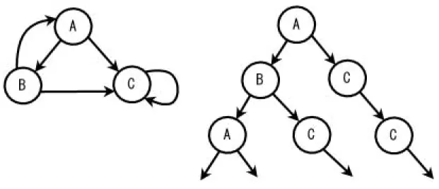
CTL formulae describe properties of computation trees. A computation tree is formed by choosing a state in a Kripke structure as the initial state and expending the structure into an infinite tree. The initial state is the root of the computation tree. This is called unwinding. Fig 2.6 shows a simple state transition graph and its unwinding. CTL for- mula is composed of ordinary logical operators and connectives plus path quantifiers and temporal operators. The path quantifiers A and E are used to describe the branching structure in the computation tree. Quantifier A indicates for all computation paths and quantifier E indicates for some computation paths. The temporal operators de- scribe properties of a path through the tree. There are mainly five temporal operators, X,F,G,U,W. A description of these temporal operators are illustrated in table 2.1.
And the usages of the combinations of these operators are described in table 2.2.
2.2.2 Verifying Properties
In CTL model checking, verification properties are decomposed to atomic propositions.
All states are checked about each atomic proposition and sets of satisfied states for each atomic proposition are obtained. From the computation using sets of states obtained, each verification property is checked and a set of states that satisfying the property is obtained.
Generally, safety and liveness properties are commonly verified in model checking:
Figure 2.6: A simple state transition graph and its unwinding Table 2.1: Temporal operators in CTL
CTL Formula Description
Xα (“next”) Property α holds at the next state of the path.
F α (“eventually”) Property α holds at some state on the path.
Gα (“globally”) Property α holds at every state on the path.
αU β (“until”) Property α holds until property β holds.
αW β Similar with U, but property β need not hold eventually.
Table 2.2: Some usages of temporal operators in CTL CTL Formula Description
AF α For every path, eventually p is true.
I.e., p is inevitable.
EF α There is some path for which p is eventually true.
I.e., p is reachable.
AGα For every computation, in every state, p is true.
EGα There exists a computation for which p is always true.
EF AGα For some combination, there is a state, such that for all paths from that state, globally p is true.
AGEF α For all computations, and for all states in it, there is a path along which eventually p occurs.
EGEF α There is a path such that from all states there is a path such that p is eventually true.
Safety Property
Safety properties usually mean the basic and important properties. For example, a mutual exclusion problem always needs to assert that resources would not being possessed by more than one process. The safety property is usually presented as formula AGα or formula AαW β in CTL.
Liveness Property
Liveness properties are the properties will eventually be true. For example, in a mutual exclusion problem, the request for a resource should eventually be accepted at some time.
Generally, properties include operator For Uare liveness properties.
However, in a mutual exclusion problem, if a resource is possessed by one process and the other processes can not get the resource, the liveness property is broken. This kind of situation is called “starvation.” To avoid such a situation, we might need an assumption that every request for a resource should be accepted, or so-called “Fairness.” There are two kinds of fairness assumption, weak and strong fairness. Weak fairness claims that chances of all processes to get a resource are the same. Strong fairness claims that the chances are the same only under the condition fors getting a resource are satisfied.
2.2.3 SMV Model Checker
There are many model checkers developed in the world. SMV(Symbolic Model Ver- ifier) [6], developed by Carnegie Mellon University, is one of the most famous model checkers. SMV checks whether a finite-state system satisfies specifications given in CTL.
SMV uses OBDD-based symbolic model checking algorithm to improve the efficiency and extend state space could be explored. The features of SMV are as follows:
Modules
A complex finite-state system can be decomposed into modules. Modules have parame- ters such as state components, expressions, or other modules. Modules can be instantiated multiple times, and modules can reference variables declared in other modules.
Synchronous and interleaved composition
SMV modules can be composed either synchronously or interleaving. Synchronous composition means a single step in a component is corresponds to a single step in other components, while in interleaving composition is exactly for the component only.
Fig 2.7 illustrates a simple example of SMV, and Fig 2.8 shows the state transition system of the example.
2.3 Relative Researches Review
MODULE main VAR
request : boolean;
state : ready,busy;
ASSIGN
init(state) := ready;
next(state) := case
state = ready & request : busy 1 : ready,busy;
esac;
SPEC
AG(request -> AF state = busy)
Figure 2.7: A simple SMV example
Figure 2.8: State transition of example in fig 2.7
There are many researches works in model checking UML models. We will describe the most related researches STP and HUGO, which are focus on model checking state machines. Some other related researches will also be introduced.
2.3.1 STP
The research Modular Translation of Statecharts to SMV introduced a STP-approach at translation STATEMATE statecharts into SMV [2]. STP gives our research the basic concepts on translating UML statecharts into SMV. The main object of STP is to reflect the hierarchical structuring of statecharts as close as possible in SMV. STP does not allow interlevel transitions whose origin and target states are in different charts respectively and statecharts are considered as close systems. The lack of STP is that the implementation is actually flattened because of its communication mechanism between modules. This makes that modules are syntactically convenient abbreviation mechanisms that makes SMV code more readable. However, STP successfully models OR-state hierarchy and precisely implements AND-chart hierarchy.
2.3.2 HUGO
The research of Model Checking UML State Machines and Collaborations [5] imple- ments a prototype tool HUGO that is designed to automatically verify whether the inter- actions expressed by a collaboration can be realized by a set of state machines. HUGO compiles UML state machines saved in XMI file into PROMELA codes for model checking in SPIN. The collaborations are compiled into sets of B¨uchi automata (“never claims”).
HUGO uses the concept of asynchronous message passing to treating events in statecharts.
A message passing(action) or a transition is executed at one step. We use the concept of message passing for our approach in modeling events in UML statecharts.
2.3.3 Other Relative Works
There are more other works relative to model checking UML statecharts. vUML [4] is similar to HUGO and developed at almost the same time. vUML is restricted to deadlock checking, where the collaboration diagrams are used to define the links between objects.
Another research translates a xUML model, an executable subset of UML, into S/R models that can be verified by the COSPAN model checker [3]. These work shows that there are many ways to implement model checking of UML model. On the other hand, a toolset based on Abstract State Machine (ASM) for supporting UML static and Dynamic Model Checking [8] is developed. In this toolset, ASM, which is originally designed for representing semantics of program languages, is extended to represent UML semantics.
Chapter 3
Model Checking UML Statechart Diagrams
As mentioned in chapter 2, our approach of model checking UML statechart diagrams is based on STP-approach and treating events and actions in reference to message passing concept described in HUGO.
3.1 Approach and Scope
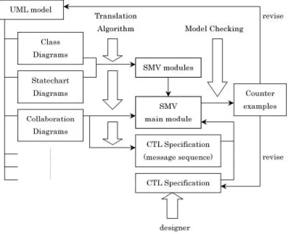
In this research, we attempt at model checking UML statecharts by SMV. For this pur- pose, we need an algorithm to translate UML statecharts into SMV codes. Fig 3.1 shows the architecture of model checking UML statechart diagrams in this research. There are other diagrams than class, statechart, and collaboration diagrams in a UML model, but we only need these three diagrams for model checking. The translation algorithm is ap- plied to class, statechart, and collaboration diagrams and we get SMV modules for each class in the UML model. Associations between classes are confirmed with class diagrams and make all relative SMV modules connected. Collaboration diagrams give the infor- mation of message sequences to form the specification to be checked and determine how the main SMV module looks like. After translation completed, the SMV model checker is applied to check the specifications. Note there is not only specifications represent message sequences but also specification given by the designer for desired properties. The revise process might be applied to UML model or designer given specifications when SMV gen- erates some counter example. As the We have not made an automatic translation tool, we apply the translation process by hand at this moment.
As illustrated in fig 3.1, the most important part of this research is the translation al- gorithm. To construct the translation algorithm, we follow the STP-approach because it quite successfully translates STATEMATE statecharts into SMV. STP-approach is quite suitable for translating UML statecharts because the structures of UML and STATEM- ATE statecharts are very similar. Unfortunately, STP-approach could not handle the
Figure 3.1: Architecture of model checking UML statechart diagrams
Figure 3.2: A hierarchal statechart in STATEMATE
message passing between UML statecharts; because STP considers STATEMATE state- chart a closed system and all events are unique in the system. For this reason, we need to adopt some parts of the STP algorithm, especially the part of event handling, for message passing of UML statecharts.
The message passing consideration refers to the algorithm introduced in HUGO. HUGO uses queue to implement the message passing asynchronously. But differently, we do not use queues for message passing but applied a similar concept in our translation into SMV. This is because the algorithm of HUGO is for translation into PROMELA, a C-like language, such that the implementation of a queue is much easier than in SMV.
To construct the relationship between UML statecharts, we need to take a look at class diagrams. In this way we might not have to handle events as global boolean variables as in STP-approach. We cannot afford to construct a mechanism of making specification properties in this research. But it is quite easy to do the same job, as in HUGO, to translate the collaboration diagrams into specification properties.
To illustrate the difference between STP-approach and out translation algorithm, fig 3.2, fig 3.3, fig 3.4, and fig 3.5 show more details these two approcah. Fig 3.2 and fig 3.3 shows an abstracted example of STATEMATE statechart and the translated SMV modules by STP-approach. We could see that the hierarchal structure of SMV modules reflects the
Figure 3.3: The architecture of SMV modules from fig 3.2 by STP-approach
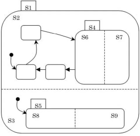
Figure 3.4: Statechart diagrams of a UML model
Figure 3.5: Translated SMV modules of fig 3.4
STATEMATE statechart well. From main module, handling of events and conditions, which are global boolean variables, are passed as parameters from top-level statechart module to the proper node of sub-statechart module.
Fig 3.4 and Fig 3.5 shows the UML statechart diagrams and the structure of SMV modules translated by out translation algorithm. Note that in UML model, structure of statechart diagram of each class could be considered like a STATEMATE statechart. But we do not use the hierarchy structure translation for one class s statechart diagram, but make the hierarchy flattened for easier accessibility of messages. Because each class has its own statechart, while in STATEMATE, all statecharts are coupled together to form a large statechart; we simply consider that one class corresponds to one SMV module and no module for its sub-chart. Of course, this will have to slightly adopt the STP algorithm.
In fig 3.5, we could see that SMV modules communicate each other when there is any association between relative classes. Not like a hierarchal architecture, SMV modules for UML statechart diagrams are independent to each other, and pass messages to associ- ated modules. One SMV module correspond to a class could be initiated more than one time to simulate the UML model behaviors. This characteristic is one of the fundamental differences between STATEMATE statecharts and UML statecharts. Another fundamen- tal difference is in event/message handling. In STATEMATE statecharts, all events and conditions are global variables and all event generation is just making the corresponding event variable true. But in UML statechart diagrams, we consider that events are treated as message passing between relative modules of corresponding classes. In this considera- tion, event generation is to pass out a message and the target of message passing is going to consume the message.
3.2 SMV Specific Language: ETL
This section gives some definition to the SMV specific language ETL. ETL is very useful for describing SMV mechanism. We will use ETL to make the translation algorithm some theoretical explanations.
ETL is a temporal language reflects the main feature of SMV language, and is enriched by a previous step-operator, defined as the converse of next step-operator. ETL has the following countable sets of symbols:
1. individual variables v1, v2, ... and constantsc1, c2, ....
2. predicate symbols P of suitable arity, including nullary init and binary equality.
3. Function symbols f of suitable arity.
4. Propositional connectives ∧,∨, ¬,....
5. Unary temporal connectives ◦ and ¯◦. The definiation of term is:
1. Individual variables are terms.
2. For a n−ary function symbol f, and termst1, t2, ..., tn, f(t1, t2, ..., tn) is a term.
ETL-formulae are defined inductively as follows:
1. P(t1, ...tn) fpr an n-ary predicate symbol P, and terms t1, ..., tn 2. ¬A, ◦A, ¯◦A for a formulaA
3. boolean combinations A∧B,A∨B, A→B for formulae A and B 4. ◦t1 =t2, ¯◦t1 =t2 for terms t1 and t2
3.2.1 Definition
An ETL time frame is a range of individuals S together with a sequence I of interpre- tations Ij, j = 0,1, ..., where Ij = Pj, Fj, Cj, such that for allj:
1. Pj(P) is a predicate on Sn for a suitable n (P’s arity) 2. Pj(=) is extensional equality, for allj
3.2.2 Definition
An ETL model is an ETL-frame together with a sequence of valuationsαj which assign every variable symbol an object from S. Given a modelM and a natural number j, the evaluation of terms in step j inductively as follows:
1. v∗j =αj(v) for individual variables v 2. c∗j =Cj(c) for individual constant c
3. f(t1, ..., tn)∗j =Fj(f)(t∗j1 , ..., t∗jn) for a function symbol f and terms t1, ..., tn Based on that, we say M, j |=A (M satisfies the formulaA in step j) if:
1. M,0|=init and M, j+ 1|=init for all j 2. M, j |=P(t1, ..., tn) if Pj(P)(t∗j1 , ..., t∗jn) = 3. M, j |=¬A if M, j |=A
4. M, j |=A∧B if M, j |=A and M, j |=B 5. M, j |=◦A if M, j+ 1 |=A
6. M,0|= ¯◦A for all formulae A 7. M, j+ 1|= ¯◦A if M, j |=A 8. M, j |=t1 =t2 if t∗j1 =t∗j2 9. M, j |=◦t1 =t2 if t∗j+11 =t∗j2
10. M,0|= ¯◦t1 =t2 for all terms t1 and t2 11. M, j+ 1|= ¯◦t1 =t2 if t∗j1 =t∗j+12
3.2.3 Lemma
For ETL-formulae A and B we have:
1. |=◦(A∧B)↔ ◦A∧ ◦B 2. |= ¯◦(A∧B)↔◦¯A∧¯◦B 3. |=◦◦¯A ↔A
4. if |=A then |=◦A 5. |=◦(¯◦t1 =t2)↔ ◦t2∧t1 6. |= ¯◦(◦t1 =t2)↔¯◦t2∧t1
Chapter 4
Translation Algorithm
The translation is constructed on the base of STP translation [2]. But we made some change to fit the UML semantic (in our consideration). Generally, in our translation from UML to SMV, one class will be translated into one module in SMV, while one sub-chart is translated to one SMV module in STP-approach. The result SMV module is mainly contains information of the relative class’s statechart diagram, including information of states, transitions, and event generation.
4.1 Class Diagrams
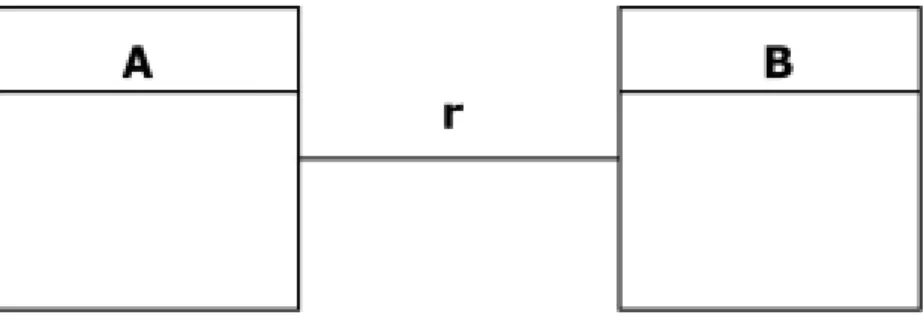
From a class diagram, the transformation algorithm figures out how many classes to be transformed to SVM modules. Associations between classes are considered as simple connections between SMV modules. This connection is presented by adding the module of each other as a parameter. For example, if there is a relation between 2 classes A and B, the class A s SMV module will have the class B s module as a parameter, and vice versa. This makes associated classes can contact each other in SMV.
More precisely, let ArB means A and B have a relation r, then the SMV modules translated will be like the SMV module segment below:
MODULE A(r,...) ... ... ...
MODULE B(r,...) ... ... ...
Where the moduleA’s parameter r means moduleB and moduleB’s parameter means module A, as showed in fig 4.1.
Or, in another design, two classes has an association which gives each class a role name.
As fig 4.2 illustrated, and the relative SMV code might be as follows:
Figure 4.1: Association Between Two Classes
Figure 4.2: Association Between Two Classes with Role Description MODULE A(r2,...)
... ... ...
MODULE B(r1,...) ... ... ...
4.2 Statechart Diagrams
The transform algorithm considering Statechart diagrams could be divided into 2 parts:
first part is considering the static properties, including the structure of a Statechart and transitions; the second part is considering the dynamic properties such as event control.
4.2.1 States and sub-states
To present states in a Statechart, simply use a variable:
state: { ..., ..., S, ..., ...};
There are two kinds of sub-states: AND and OR sub-states. To present sub-states in SVM modules, simply use one more state variable like the segment below:
Figure 4.3: AND and OR sub-states -- OR sub-state S:
state S: {..., ..., Sn, ...}; -- AND sub-state S:
state S1: {..., ..., S1n, ...}; state S2: {..., ..., S2n, ...};
In sub-states, there will be one more state not defined in UML statechart, which is called NULL. When the sub-chart is not active the state of the sub-chart is in NULL state. Here we introduce some ETL-predicates to formalize our translation more easily.
• states(sc) : the state set of statechart ( or a sub-chart) sc.
• state(sc) : active state in statechart ( or a sub-chart) sc. For example, state(sc) = S.
• chart(S) : the (sub-)statechart that state S directly belongs to. For example, chart(S) = sc.
• initial(S) : stateS is the initial state of the statechart or subchart directly belongs to.
• active(sc) : (sub-)statechart sc is active, which means the controlling state is insc.
• substate(Ssub,S) : substate Ssub is directly contained in stateS.
To take a reference to segments of SVM modules above, sc could be considered as the state variable state or state S, and S as an element in that state variable. The predicate active(sc) could be considered that controlling state is in the sub-state Ssc, where state = Ssc. And active(sc) ↔ state(sc0) = Ssc, where sc0 denotes sc’s upper statechart. The top state (or say, statechart) is always active.
4.2.2 State Transitions
letsuccs(S) be the set of direct successors of a stateS. The predicateguard(S, T) is the evaluation of the translation guard of the transition from S to T. A transition can only be taken when its guard evaluates to true. Also, state transition is nondeterministical.
Per (sub-)charts only one transition can be taken in each step. Assume the state is in S for the current step, and some of the guards on the outgoing transitions are true. In the case that more than one guard is true, one transition is non-deterministically chose.
When no guard is true or succs(S) is empty, active state remains in S. The ETL formula about transitions is as follows:
active(sc)→
S∈state(sc)
[ state(sc) =S
∧ (
T∈succs(S)
(guard(S, T)∧o(state(sc) =T))
∨ (
T∈succs(S)
¬guard(S, T)∧o(state(sc)) =state(sc)) ) ]
LetS1, ..., Snbe the successors of the stateSandCj the respective guards, andT1, ..., Tm be the successors of the state T and Dj the respective guards.
TRANS
( (active Ssc & state = S & ( (C1 & next(state) = S1) | ... ... ...
(Cn & next(state) = Sn) |
(!C1 & ... & !Cn & next(state) = state) )) ... ... ...
| (active Ssc & state = T & ( (D1 & next(state) = T1) | ... ... ...
(Dm & next(state) = Tm) |
(!D1 & ... & !Dm & next(state) = state) )) ... ... ...
| !active Ssc & state = NULL)
Where “active Ssc” denotes that the upper statechart is in state Ssc. For example,
“state = Ssc” while the parent statechart is top-level statechart or “state S = Ssc”
while the parent statechart isS. And, transitions in the top-level statechart are as follows:
TRANS
( (state = S & ( (C1 & next(state) = S1) | ... ... ...
(Cn & next(state) = Sn) |
(!C1 & ... & !Cn & next(state) = state) )) ... ... ...
| (state = T & ( (D1 & next(state) = T1) | ... ... ...
(Dm & next(state) = Tm) |
(!D1 & ... & !Dm & next(state) = state) )) ... ... ...
Where the active variable disappears because the top-level statechart is always active.
Also, the top-level statechart does not have N U LL state.
4.2.3 Activation and deactivation of sub-charts
The definition about activation and deactivation of subcharts are as follows:
Definition:
LetSsub−j, j = 1...n be the subcharts ofS (n= 1 if S is an OR-state,n > 1 ifS is an AND-state):
1. As long as the active state is not S, Ssub−j is in N U LL state.
2. On the same step the active state reaches S, all Ssub−j are initialized, and control moves to the target state of the initial state(s) of Ssub−j.
3. As long as the active state is inS,Ssub−j perform their state transitions as any other statecharts.
4. The active state leavesSas soon as any of the outgoing transition fromS is enabled.
5. Ssub−j is set toN U LL state on the same step the active state leaves S.
4.2.4 Transitions in and out a sub-chart
When a transition leads to stateSsub occurs and Ssub is a subchart, the active state in Ssub is set to the initial state of Ssub from state N U LL. If there is a pseudo-state initial, initial is the initial state of the subchart. For the transition goes out of Ssub, there are 2 situations:
Letsc0 be the upper statechart of sub-chartsc. If the source of the transition leavessc is simply the sub-chart sc, then this transition is only considered a normal transition in sc0. In the case that the source of outgoing transition is a state in sc, then a condition state(sc) =Sout should be added to the guard(s) of the outgoing transition, where Sout denotes the source state of the outgoing transition in sub-chart sc.
(2) The subchart completes or ceases its activities and a transition goes out of Ssub is triggered:
In the case that the sub-chart is an AND-state, the sub-chart completes its activities when all its sub-charts reach the final states which has no successor states. In this case the outgoing transition is usually a non-guard transition. Simply addinng a guard that all AND-state’sendstate is reached should be work. Letsc1andsc2 be the AND sub-charts of sc, then the guard of the outgoing transition looks like: (state(sc1) =Send1∧state(sc2) = Send2), whereSend1 and Send2 denote endstates of sc1 and sc2 respectively.
4.2.5 Compound events
Compound events en(S), ex(S), and in(S) are already defined in STP-approach [2].
They are defined in STATEMATE semantics, but not clearly defined in UML statechart semantics. We still use these events because they are useful as triggers of entry and exit action. The definition is as follows:
T L(en(s)) = active(sc)∧state(sc) =s
∧ [ ( ¯o(active(sc))∧(¯o(active(sc)) =s→(¯o(guard(s, s))∧s∈succs(s))) )
∨ (¯o(¬state(sc) =s)∧initial(s)) ] T L(ex(s)) = ¯o(active(sc))∧o(state(sc) =¯ s)
∧ ( state(sc) =s →active(sc)→(s∈succs(s)∧o(guard(s, s))) )¯ T L(in(s)) = active(sc)∧state(sc) =s
Where T Lmeans temporal logic semantics.
4.2.6 Initial States
When a statechart enters a state that contains subcharts, the subchart enters its initial state immediately. To define the situation, we can use the definition of en(s) to get the following ETL formulae:
en(Ssc)→state(sc) = S0
Where S0 is the initial state of sub-chart sc.
4.3 Event Control
This section illustrates our considerations about events and conditions. The ideas of event and condition treatment are based on STP translation. Due to some differences of semantics between STATEMATE and UML statechart, we must adapt some portion of the STP translation.
4.3.1 Definition
Since the UML semantics of statechart diagrams in message passing is not clearly defined. We need an explanation of message passing for our translation algorithm. We use a concept like queue but not actually applying queue. The considerations about event control are basically as follows:
1. The event generation in UML is basically by message passing. Each module sin SMV has its own event variables, while in STATEMATE, all events are global boolean variables.
2. Message passing is between statecharts, or say, from one class to another class.
Message passing from and to the same statechart also exists.
3. It is restricted that a statechart can only accept message passing from one statechart (including from itself) at one time step. When there are message passing from two or more statecharts for one statechart are going to happen, only one statechart could send the message. This means other statecharts could not send message at this time step and they should stop or delay till next time stop to execute their transitions that generate the message passing.
4. When a delay in a statechart happens, the delayed transition has to be executed next time step. This makes that the statechart cannot accept message passing from other statecharts. If there is any statechart tempt to send message to the delayed statechart, it should also be deferred.
5. Because of the delay mechanism, an event might not be consumed in a delay situa- tion. The boolean variable of the delayed event should remain true for the execution on next time step. To represent the difference between delay and normal event ex- ecution, the normal event execution is considered as consuming an event. The boolean variable of an event is set to false when the consuming occurs, while in a delay situation the event variable may remain true because of no consuming occurs
4.3.2 Event Variables
Events are defined as Boolean variables as in STP-approach. But event variables are not treated as global variables but attributes of statechart modules in SMV. According to definitions in section 4.3.1, the declaration of event variables is like following segment of SMV code.
VAR
E: boolean; set E r: boolean;
... ... ...
DEFINE
reset := !delay;
In the SMV code, there are event variable itself and other related variables asset and reset to the event variable. The set event variable is true when a message passing to the statechart happens, and thereset event variable is true when the statechart execute a transition, which means this event is consumed. Note that the reset event variable is not specified for eventE only but for all event variables. This is because we consider that event consuming is the same as in STATEMATE where events are available only one time step even the transition executed is not related to the event. The reset event variable is defined as the negation of boolean variable delay.
To set and reset the event variable, we use the SMV code segment below. Note the line
“reset & !(set r1 | set r2 | … | set rn) : 0;.” When the statechart execute a transition and reset is true, the event variable should be reset to false only when all set event variables are not true. If one of the set event variables is true, the event variable should be set to true so that the event at the next step will wait to be consumed. Because we assume that only one message passing is allowed to the statechart at one time step, only one set event variable is true at the same time step. And if delay situation happens, the event variable will keep its value. Actually, in our assumption, in a delay situation, a statechart would not accept any message passing to it so that all set event variables are false at that time step, include the reset variable.
INIT E = 0;
ASSIGN
next(E) :=
case
next(set E r1) : 1;
next(set E r2) : 1;
... ... ...
next(set E r1) : 1;
reset & !( next(set E r1) | next(set E r2) |...| next(set E rn)):0;
1 : E;
esac;
Sending messages to another statechart, or say, an action, is triggered by the relative transition execution. Assume that source(t) and target(t) are the source and target of transition t, and T is the set of transitions that trigger event E, then we have:
t∈T
[ ¯◦state(sc) = source(t)∧¯◦active(sc)
∧ active(sc)∧state(sc) =target(t) ]↔E And we could write the following SMV code:
ASSIGN
next(r.set E r) :=
case
active Ssc & next(active Ssc) & state = S1 & next(state) = T1:1;
active Ssc & next(active Ssc) & state = S2 & next(state) = T2:1;
... ... ...
active Ssc & next(active Ssc) & state = Sn & next(state) = Tn:1;
1 : 0;
esac;
4.3.3 Mutual Exclusive Message Passing
To implement the mutual exclusive message passing mechanism, source and target of message passing have to know the delivery status of the event. We define a predicate send(r) to figure out if there will be potentially a message passing out the statechart to the module has association r.
send(r) :=
t∈T r
[active(sc)∧state(sc) =source(t)∧guard(t)]
Where Tr is the set of transitions that may send messages from this statechart to the statechart with association r, and guard(t) means the guard of a transition. The corresponding SVM code segment looks like:
ASSIGN send r :=
case
active Ssc & state = S1 & E1 : 1;
active Ssc & state = S2 & E2 : 1;
... ... ...
active Ssc & state = Sn & En : 1;
1 : 0;
Further more, we also define a variable clash to detect that if more than one statecharts are tempt to send messages. Let R be the set of association presented in class diagrams.
Two or more modules that tempt to send messages to the statechart will cause a message- passing clash.
clash:=
r1,r2∈R,r1=r2
[send(r1)∧send(r2)]
The implementation in SMV code is more complicate. We define clash variables clash r1, ..., clash rn relative every associated statechart module. We also define the clash variable. But the clash variable is not defined as boolean but as an enumeration include elements represent clash r1, ..., clash rn. When the clash of message passing is occurs, all associated clash variables should be set to true except one variable is set false.
This variable is set false because the message sent by the associated statechart will be accepted. The enumerated clash variable may help the implementation easier. For exam- ple, a statechart module has three associated statechart modules might gives the SMV code about clash as follow:
VAR
clash : { R1,R2,R3,none }; ASSIGN
clash :=
case
r1.send r1 & r2.send r2 & !r3.send r3 : R1,R2;
r1.send r1 & !r2.send r2 & r3.send r3 : R1,R3;
!r1.send r1 & r2.send r2 & r3.send r3 : R2,R3;
r1.send r1 & r2.send r2 & r3.send r3 : R1,R2,R3;
1 : none;
esac;
DEFINE
clash r1 := !(clash = none) & !(clash = R1) & r1.send r1;
clash r2 := !(clash = none) & !(clash = R2) & r2.send r2;
clash r3 := !(clash = none) & !(clash = R3) & r3.send r3;
Where element “none” of enumeration variable clash means no clash happens.
As the clash variables are defined, we could then define delay variable. The delay variable is set true when the statechart is tempt to send messages to a target statechart but the target statechart has a clash situation or is in delay situation. Let Ris the set of associate statecharts. We can get an ETL formula as follows:
delay :=
r∈R
[send(r)∧(clash(r)∨delay(r))]
We can write the corresponding SMV code segment below:
ASSIGN
delay := case
send r1 & (r1.clash r1) | r1.delay) : 1;
send r2 & (r2.clash r2) | r2.delay) : 1;
... ... ...
send rn & (rn.clash rn) | rn.delay) : 1;
1 : 0;
esac;
Finally, all transitions have to add a guard !delay such that the exclusive message passing mechanism may take effect.
TRANS
( (active Ssc & state = S &
((!delay & C1 & next(state) = S1) | ... ... ...
(!delay & Cn & next(state) = Sn) |
(!delay & !C1 &...& !Cn & next(state) = state))) ... ... ...
| (active Ssc & state = T &
((!delay & D1 & next(state) = T1) | ... ... ...
(!delay & Dm & next(state) = Tm) |
(!delay & !D1 &...& !Dm & next(state) = state)))
| (active Ssc & delay & next(state) = state)
| !active Ssc)
For the top-level statechart, the SMV code is:
TRANS
( (state = S & ((!delay & C1 & next(state) = S1) | ... ... ...
(!delay & Cn & next(state) = Sn) |
(!delay & !C1 &...& !Cn & next(state) = state))) ... ... ...
| (state = T & ((!delay & D1 & next(state) = T1) | ... ... ...
(!delay & Dm & next(state) = Tm) |
(!delay & !D1 &...& !Dm & next(state) = state)))
| (delay & next(state) = state)
Figure 4.4: Restriction of generating Method call
4.3.4 Method Calls
Some messages/events are method calls that defined in the class diagram. In our consideration, method calls are not only message signals but something like function calls.
We assume that only at some states can a method be invoked. Transitions in a statechart diagram could help figure out at which states a method is available to be invoked. When a state has a transition that triggered by a method call, we say at that state the method call is available. Or when a method is included in activities of a state, the method call is also available at that state.
To represent the availability of a method call, we consider that every transition that generates a method call message should be applied a condition that the method call is available at the next time step. It is a little tricky that a method call should be available at the next time because to send a message, not only a method call, takes one time step to reach the target statechart. As fig 4.4 shows, a restrict condition is added when translating statechart diagrams into SMV.
4.4 Collaboration Diagrams
The translation of collaboration diagrams is basically doing two jobs:
1. Determine how many variables of SMV modules translated from statechart diagram should be declared in the main module.
2. Get the message passing sequence to construct a CTL equation for SMV.
We use an abstracted simple example to illustrate the translation algorithm. Consider the example of a collaboration diagram showed in fig 4.5. There are two classes linked with an association r in the diagram. In usual collaboration design, we do not have to
Figure 4.5: A simple collaboration diagram
specify the associations, but here we have to specify in order to match with the class diagram.
The first step of translation is to confirm the classes and associations in collaboration and decide what modules we translated from statechart diagrams should be used in main module and how many instances should participated in the model checking. In this example, we will make a SMV main module below:
MOUDLE main A: a(r);
B: b(r);
... ... ...
Where the module A and B are declared as global variables a and b.
The second step of translation is to construct a CTL formula for model checking from the message sequence illustrated in collaboration diagram. In fig 4.3, there are four messaged sent, two from object a and two from object b. The translation will figure out the order of these messages and then make a following CTL formula in SMV code:
SPEC
AF (b.m1 & AF (b.m2 & AF (a.m3 & AF a.m4)))
The formula means that the message sequence should be obeyed in all computation.
Note that the messages which are specified the name themselves are members of the target module. We could make another CTL formula that shows weaker assurance, in which the message sequence is not globally followed but only has a chance to occur.
SPEC
EF (b.m1 & AF (b.m2 & AF (a.m3 & AF a.m4)))
Figure 4.6: A delay deadlock
4.5 Problems and Discussions
As mentioned before, out translation algorithm is based on STP-approach, but we made some adaptation to suit the semantic and structure of UML statechart diagrams. There are two main differences between our approach and STP-approach. First, in our approach, the modular translation is for statechart of each class, while in STP-approach the modular translation is for statecharts and sub-statecharts. Second, the event handling mechanism is considered complicated in UML statecharts than in STATEMATE statecharts. The reason might be that in STATEMATE all event and statecharts are well arranged so that no confliction of event passing will occur. And it is an un-avoidable problem in UML statechart that how to handle event/message passing.
Examining our translation algorithm in message passing, which uses the concept of queue but not defines any queue module, there are some problems that should be con- sidered. As the messages in a queue may over the size of the queue, it is reasonable to consider that our translation may cause a dead lock when all message passing are delayed.
This may happens in some problems have deadlock properties. But the question is may our message-passing algorithm cause more other deadlocks. Fig 4.6 illustrates an example that a delay deadlock happens.
Chapter 5 Examples
5.1 Dining Philosophers
Dining philosophers problem is a typical mutual-exclusion problem, and is rather simple enough to be understood and illustrated. We implemented a two philosophers and two forks system in UML. Fig 5.1 shows the class diagrams. Fig 5.2 and fig 5.3 show the statechart diagrams. Fig 5.4 shows the collaboration diagrams.
In this system, there are two classes Philosopher and Fork, and the associations between them are left and right, which means one fork is at a philosopher s left hand and another fork is at the philosopher’s right hand. We write the SMV codes that represent the associations.
MODULE Philosopher(left, right) ... ... ...
... ... ...
MODULE Fork(left, right) ... ... ...
Because Philosopher and Fork do not have sub-charts, their state variables are simple.
VAR
state : { Thinking, WaitingLeft, Eating, Releasing}; ... ... ...
... ... ...
VAR
state : { Available, Taken}; ... ... ...
Figure 5.1: Class diagrams of Dining Philosopher Problem
Figure 5.2: Statechart diagram of Fork
Figure 5.3: Statechart diagram of Philosopher
Thesetvariables for message passing are only in module Philosopher, and the following SMV code segment shows how module Philosopher send a message that calling get method of left hand fork.
ASSIGN
init(left.set get left) := 0;
next(left.set get left) :=
case
state = Thinking & next(state) = WaitingLeft : 1;
1 : 0;
esac;
The implementation ofsend variable and delay variable are as following. Send left is set true when the state is in Thinking or Releasing and the guard of next transition is true. The delay variable is not complicate because there are only two relations to module Fork.
ASSIGN
send left :=
case
state = Thinking & left.in Available : 1;
state = Releasing : 1;
state = WaitingLeft : 0;
state = Eating : 0;
esac;
ASSIGN
delay := case
(send left & left.clash left) | left.delay : 1;
(send right & right.clash right) | right.delay : 1;
1 : 0;
esac;
The transitions in module Philosopher uses TRANS for implementation. Note the delay variable in the code.
TRANS
((state = Thinking &
((left.in Available & !delay & next(state) = WaitingLeft) | (!left.in Available & next(state) = state)))
| (state = WaitingLeft &
((right.in Available & !delay & next(state) = Eating) | (!right.in Available & next(state) = state)))
| (state = Eating & ((!delay & next(state) = Releasing) | (next(state) = state)))
| (state = Releasing & ((!delay & next(state) = Thinking) | (next(state) = state)))
| (delay & next(state) = state))
For module Fork, we may focus on the message handling part, how set and reset vari- ables influence events and how clash variable is implemented.
ASSIGN
init(get) := 0;
next(get) :=
case
next(set get left) : 1;
next(set get right) : 1;
reset & !(next(set get left) & next(set get right)) : 0;
1 : get;
esac;
ASSIGN
clash := case
left.send left & right.send right : {L,R}; 1 : none;
esac;
DEFINE
clash left := clash = L;
clash right := clash = R;
We design five properties for model checking.
1. AF ((fork1.get & AF fork2.get) | (fork2.get & AF fork1.get)) 2. AF (philo1.state = WaitingLeft & AF philo1.state = Eating)
4. AF ((philo1.state = WaitingLeft & philo2.state = WaitingLeft) & AF philo1.state
= Eating)
5. EF ((philo1.state = WaitingLeft & philo2.state = WaitingLeft) & AF philo1.state
= Eating)
First property is as illustrated in collaboration that philosopher1 and philosopher2 send get message to fork1 and fork2 respectively. We write a little different CTL formula because that there are two orders of the two messages be sent. The second and third formulas are almost the same except the path operator at head. They are properties of possibilities that a philosopher can get to the Eating state. They are designed for examining the deadlock situation that two philosophers may have one fork in left hand and waiting the fork at right hand side that is taken and unavailable. The fourth and fifth properties exactly represent the deadlock situation, and also use different path operator at the head.
The result for first property is true because the two philosophers will get their left hand fork first. The second property is false. The counter example shows that two philosophers have a fork at their left hand and waiting the right fork available. The third property is false but not exactly a counter example is showed because the operators EF get a false result while the root state has not path satisfy the property. The results of fourth and fifth properties are the same as second and third.
Actually, after observing the results, we found that the two philosophers get their left hand fork at the same time and this makes the deadlock inevitable. As a solution for the deadlock, we may consider a new statechart for philosopher as illustrated in fig 5.5.
In fig 5.5, state Thinking has another transition that goes to itself and this may make two philosophers not always get the left hand fork at the first time step. Then, two philosophers could have chance to get all two forks and have dinner.
The transition in module Philosopher should be added a line for the self-transition of state Thinking.
TRANS
((state = Thinking &
((left.in Available & !delay & next(state) = WaitingLeft) | (!delay & next(state) = Thinking) |
(!left.in Available & next(state) = state)))
| (state = WaitingLeft &
((right.in Available & !delay & next(state) = Eating) | (!right.in Available & next(state) = state)))
| (state = Eating & ((!delay & next(state) = Releasing) | (next(state) = state)))
| (state = Releasing & ((!delay & next(state) = Thinking) | (next(state) = state)))
For the new design, the results of all three properties are false. The third property is obviously false it is the dead lock situation. First property is false because it is possible
Figure 5.5: Revised Statechart diagram of Philosopher
that philosopher1 get his left hand fork and philosopher2 is still thinking. The third property is false because the same reason as first property.
5.2 Discussions
After examining some properties in Dining Philosopher Problem, we found that our translation algorithm could work properly although the results of verification are not so pure. This is because more situations are possible in the simple example. And this result also indicates that finding a proper property is not so easy.
Chapter 6
Conclusions and Future Works
6.1 Conclusions
We constructed a translation algorithm that could translate UML statechart diagrams into SMV modules. The algorithm treats statecharts, sub-statecharts, and also handles message passing in mutual exclusive way. The examples show that the algorithm works somehow properly. But the algorithm does not cover all the semantics of UML statechart diagrams. For example, the algorithm does not support history state and attributes.
This makes the algorithm unable to apply very well although we could redesign a model suitable for the algorithm.
6.2 Future Works
We may continue for some works after the translation algorithm is constructed:
Coverage of UML statechart diagrams
As described in section 6.1, the translation algorithm still has space to improve such as supporting history statesstates and attributes handling, etc. It should be the first task to do in the future.
Automatic translation tool
We examined the examples and translated the UML model by hand. It is needed that an automatic translation tool to be developed. Actually there are technologies suitable to develop the translation tool. UML model saved in XMI format could be processed by XML parsing tools such as DOM, and then do the translation algorithm in program written in JAVA or C++.
Finding proper verification properties
At this time, we still have to find out by ourselves the suitable verification properties.
The information from the collaboration diagrams is only message sequences and properties about states cannot be represented. It should be helpful if some other properties can be generated by transform algorithm for the designer.
Bibliography
[1] Edmund M. Clarke, Jr., Orna Grumberg, and Doron A. Peled, Model Checking, 4th ed., MIT Press, 2002.
[2] E. M. Clarke W. Heinle, Modular Translation of Statecharts to SMV, CMU-CS-00- XXX, Aug. 2000.
[3] F. Xie, Levin and J.C. Browne, Model Checking for an Executable Subset of UML, In Proceeding of Automated Software Engineering, 2001.
[4] Lilius, Ivan Porres Paltor, vUML : a Tool for Verifying UML Models, In14th IEEE International Conference on Automated Software Engineering, Oct. 1999.
[5] Schafer T., Knapp A., Merz S., Model Checking UML State Machines and Collabo- rations, Electronic Notes in Theoretical Computer Science 47, 2001.
[6] SMV manual, http://www-2.cs.cmu.edu/ modelcheck/smv.html [7] UML semantics 1.1, Sep. 1997.
[8] Wuwei Shen, Kevin Compton, and James K. Huggins, A Toolset for Supporting UML Static and Dynamic Model Checking, 26th International Computer Software and Applications Conference Aug. 2002,
Appendix A
Code and Results of Dining Philosophers Problem
A.1 SMV code
---- Dining Philosopher Problem ---- MODULE Philosopher(left, right) VAR
state : {Thinking, WaitingLeft, Eating, Releasing};
ASSIGN
init(state) := Thinking;
TRANS
((state = Thinking & ((!delay & next(left.available_get)
& next(state) = WaitingLeft) | (!delay & next(state) = Thinking) | (!delay & !next(left.available_get)
& next(state) = state)))
| (state = WaitingLeft & ((!delay & next(right.available_get)
& next(state) = Eating) | (!delay & !next(right.available_get)
& next(state) = state)))
| (state = Eating & ((!delay & next(right.available_release)
& next(state) = Releasing) | (!delay & !next(right.available_release)
& next(state) = state)))
| (state = Releasing & ((!delay & next(left.available_release)