A NEURAL NETWORK BASED ADAPTIVE ARM MOTION GENERATION FOR ASSISTIVE HUMANOID ROBOTS
人間型介助ロボットのニューラルネットによる適応アーム動作生成 人間型介助ロボットのニューラルネットによる適応アーム動作生成人間型介助ロボットのニューラルネットによる適応アーム動作生成 人間型介助ロボットのニューラルネットによる適応アーム動作生成
ZULKIFLI MOHAMED
Dissertation submitted in partial fulfilment for the degree of Doctor of Philosophy
Graduate School of Science and Engineering University of Toyama
February 2014
- i - Acknowledgements
Syukur Alhamdulillah. It would not have been possible to write this doctoral thesis without the help and support of the kind people around me, to only some of whom it is possible to give particular mention here.
First and foremost I would like to express my deepest gratitude to my PhD advisors, Professor Genci Capi for excellent guidance, caring, patience and providing me with an excellent atmosphere for doing research. He has been very helpful in an- yway, supportive and kind since the first day I arrived in Toyama. His endless support not only in my research but also to my family and my life here in Toyama.
Without his guidance, it would be almost impossible for me to complete my PhD.
I would like to thank to all Intelligent Robotics Laboratory members especial- ly to Toda sensei for having me as one of his student, Kitani sensei for helping me on translating all the paper works and for sharing his knowledge and experience, Mano for being my only roommate for the past three years and it would have been a lonely lab without him. Many thanks to Ishikawa and Takeuchi for helping me on the mo- bile platform and also Shirakawa-san from Mechanical Engineering Workshop for helping me on the machining part of the robot.
Thanks to all my Malaysian friends in Toyama for the best experience ever, for helping and guiding me in so many things, to my officemate in the Faculty of Mechanical Engineering UiTM Shah Alam, especially the top management lead by the Dean, Professor Ahmed Jaffar and not forgotten Azli, Azhan, Alias, Afzan, Halim, Bidin, Hafiz, Man, Azzeim, Skano, Arai, Fazli, Che We, Liana and Pak Lah.
I would also like to thank to the Malaysian Government specifically Ministry of Education Malaysia and Universiti Teknologi MARA for giving me this oppor-
- ii -
tunity to do my PhD here in University of Toyama by providing financial support to me and my family for the past three and a half years.
A special thanks to my beloved wife, sons and daughter, my mom, brothers and sister and to my late father for endless support and doa. My doa will always for all of you.
- iii -
This dissertation is lovingly dedicated to my wife, Ida Rohayu, for always being there for me.
Her support, encouragement, doa and constant love have sustained me throughout my life.
- iv - Abstract
In the recent years the number of ageing population has been increasing. In the coming decades, this scenario will lead to high demand for health care and financial resources. The ability to do house hold chores such as cleaning, picking the trash or taking a bottle of water from the kitchen becomes much harder for the elderly. One of the solutions is by having personal assistive robots to help with the daily activities and task.
As humanoid robots are expected to operate in human environments they are expected to perform a wide range of tasks. Therefore, the robot arm motion must be generated based on the specific task. In this thesis, we propose an optimal arm mo- tion generation satisfying single and multiple criteria. In our method, we evolved neural controllers that generate the humanoid robot arm motion in dynamic environ- ment optimizing three different objective functions: minimum time, minimum distance and minimum acceleration. An advantage of proposed method is that in a single ran of MOEA multiple neural controllers are generated. In addition, the same neural controller can be employed to generate the robot motion for a wide range of initial and goal positions. The robot motion generation in dynamic environments is also considered.
A new mobile humanoid robot system has been developed in our lab to test the performance of the proposed method. The robot consists of two main parts, the upper body for object manipulation and the mobile platform for robot navigation. The hu- manoid robot has ten degrees of freedom in both arms, two degrees of freedom head and two grippers. The robot is equipped with two cameras and two laser range find- ers for assisting the robot while navigating, localization and object recognition.
- v -
We tested the evolved neural controller in a simulated and on the real robot.
The results show good performance. Although the results in simulated environment and on the real robot have some differences, the robot is capable of maintaining its trajectory and completes the task successfully.
- vi - Abstract (Japanese)
近 年 、 世 界 的 に 高 齢 化 が 進 ん で お り 、 高 齢 者 に 対 す る 身 体 的 な い し 経 済的な補助が急務となっている。若年者は、清掃やゴミ出し、物の運搬とい った家事を容易に行うことができるが、高齢者は、身体能力の低下のために これらの動作を行うことが困難となる。よって、高齢者を日常的に補助する ための、個人用介助ロボットの需要が高まっている。
介 助 ロ ボ ッ ト は 、 一 つ の 動 作 を 繰 り 返 し 行 う も の よ り も 、 様 々 な 動 作 を行うことが期待されるが、ロボットの腕部の動作は特定の動作を基準とし て生成されることが好ましい。本論文では、ロボットの腕部動作生成のため の最適化手法について検討した。本論文における提案手法は、最少時間と距 離、加速度の 3 つの目的関数を最適化することで、動的環境におけるロボッ トの腕部動作を生成することができる。また、1 つの多目的進化型アルゴリ ズム (Multi-objective Evolutionary Algorithm: MOEA)によって複数のニューラ ルコントローラを生成することが可能である。加えて、ニューラルコントロ ーラはロボットの動作開始地点と終了地点を変更しても、利用することがで きる。
本 提 案 手 法 を 実 装 す る た め の 人 型 ロ ボ ッ ト を 構 築 し た 。 ロ ボ ッ ト は 、 物体を操作するための上半身と移動のための下半身の 2 つから構成されてい る。上半身の自由度は、2自由度の頭部と把持部を含む 10自由度である。ま た、センサとしてステレオカメラと 2 つのレーザレンジファインダが設置さ れており、これらを用いて、物体認識と定位、移動を行うことができる。
- vii -
ョン環境で進化させ、ロボットに実装した。結果として、ロボットは良好に 腕部動作を生成することができた。シミュレーション環境と実環境では差が あるものの、ロボットはシミュレーション環境で獲得した腕部の軌道を保ち つつ、良好にタスクを実行することができた。
- viii - Table of Contents
Acknowledgements ... i
Abstract ... iv
Abstract (Japanese) ... vi
Table of Contents ... viii
List of Tables ... xi
List of Figures... xii
1 INTRODUCTION ... 1
1.1 Background ... 2
1.2 Research Goal ... 3
1.3 Achievements ... 3
1.4 Thesis Outline ... 3
2 LITERATURE REVIEW ... 5
2.1 Assistive Humanoid Robots ... 8
2.1.1 System Integration ... 11
2.2 Arm Motion Generation ... 13
2.2.1 Arm Motion as an Optimization Problem ... 15
3 MOBILE HUMANOID ROBOT PLATFORM ... 18
3.1 Kinematics Analysis ... 19
3.1.1 Denavit-Hartenberg (DH) Parameters ... 19
3.1.2 Inverse Kinematics ... 21
3.2 Mechatronics Design & Hardware Architecture ... 23
3.2.1 Upper Body ... 23
3.2.2 Mobile Platform... 26
3.2.3 Electronic Components ... 27
3.2.3.1 DC Motors ... 27
3.2.3.2 AC Motors ... 27
- ix -
3.2.3.3 Servo Motors ... 28
3.2.3.4 Laser Range Finder (LRF) ... 29
3.2.3.5 Potentiometers ... 31
3.2.4 Software Architecture ... 31
3.2.4.1 MATLAB Simulation ... 31
3.2.5 System Integration ... 32
3.3 Kinesiology of the Robot Motion ... 35
4 EVOLUTION OF NEURAL CONTROLLERS ... 38
4.1 Problem Formulation ... 38
4.1.1 Robot Arm Tasks Selection ... 39
4.1.2 Arm Motion Generation ... 42
4.1.3 Proposed Method ... 43
4.2 Neural Networks ... 44
4.3 Genetic Algorithms (GA) ... 46
4.3.1 Multi-Objective GA ... 47
4.3.2 Objective Functions ... 47
4.3.2.1 Arm Motion Objective Functions ... 48
4.3.2.2 Minimum Execution Time (MT) ... 48
4.3.2.3 Minimum Distance (MD) ... 49
4.3.2.4 Minimum Acceleration (MA) ... 50
4.3.2.5 Minimum Angular Acceleration (MAA) ... 51
4.3.3 Robot Navigation ... 51
4.3.3.1 Environment 1... 51
4.3.3.2 Environment 2... 52
4.3.3.3 Environment 3... 53
4.4 Arm Motion Generation in Dynamic Environment ... 54
5 SIMULATION AND EXPERIMENTAL RESULTS ... 57
5.1 Single Objective Optimization ... 57
- x -
5.1.1 Simulation Results ... 58
5.1.2 Experimental Results ... 61
5.2 Multi Objective Optimization ... 67
5.2.1 Two Objective Optimization ... 67
5.2.1.1 Simulation Results: Minimum Time & Minimum Distance: (f1-f2) ... 67
5.2.1.2 Simulation Results: Minimum Time & Minimum Acceleration: (f1-f3) .... 69
5.2.1.3 Simulation Results: Minimum Distance & Minimum Acceleration: (f2-f3)71 5.2.1.4 Experimental Results: Two Objective Optimization... 73
5.2.2 Three Objective Optimization ... 78
5.3 Neural Controllers Performance and Obstacle Avoidance ... 83
5.4 Robot Navigation ... 94
6 CONLCUSION AND DISCUSSION ... 105
6.1 Future Work ... 106
REFERENCES ... 108
APPENDIX A:... 117
APPENDIX B:... 119
APPENDIX C:... 120
- xi - List of Tables
Table 3- 1 D-H Parameters. ... 20 Table 4-1 Summary of genetic algorithm parameter. ... 46 Table 5-1 Simulation parameters... 86
- xii - List of Figures
Figure 1-1 Changes of population pyramid (a) World (b) Japan (c) Malaysia. ... 6
Figure 1-2 Age structure population by country... 7
Figure 1-3 Developed mobile humanoid robot (a) TWENDY-ONE (b) ARMAR III (c) RIBA (d) Dynamaid (e) Snackbot (f) PR2. ... 7
Figure 3-1 Coordinate frame of the robot upper body………...………….19
Figure 3- 2 Inverse kinematics analysis of the robot hand. ... 22
Figure 3-3 Right hand design of the mobile humanoid robot. ... 24
Figure 3-4 Left hand design of the mobile humanoid robot. ... 25
Figure 3-5 Mobile platform. ... 26
Figure 3-6 DC Motors and motor drivers. ... 26
Figure 3-7 AC Motors. ... 27
Figure 3-8 Servo motors. ... 28
Figure 3-9 Laser range finder. ... 28
Figure 3-10 (a) Obstacle detection via LRF1 (mobile platform) (b) Spray can detection via LRF2 at table height (upper body). ... 30
Figure 3-11 Potentiometers. ... 31
Figure 3-12 (a) Robot arm simulator (b) GUI. ... 33
Figure 3-13 Developed mobile humanoid robot. ... 34
Figure 3- 14 System Integration ... 35
Figure 3- 15 Robot head movements. ... 36
Figure 3- 16 Robot arm movements. ... 36
Figure 3-17 Robot hand flexion and extension movements. ... 37
Figure 3-18 Robot hand supination, semiprone and pronation movements. ... 37
- xiii -
Figure 4-1 Task 1: Placing a bottle on the table. ... 39
Figure 4-2 Experimental setup for reaching the table ... 40
Figure 4-3 Task 2: Reaching a spray can on the table and picking motion to a holding position. ... 41
Figure 4- 4 Task 3: Reaching a spray can on the table while avoiding obstacle ... 41
Figure 4-5 FFNN for mobile platform. ... 45
Figure 4-6 FFNN for robot arm. ... 45
Figure 4-7 GA Cycle. ... 48
Figure 4-8 Robot navigation in environment 1. ... 52
Figure 4-9 Robot navigation in environment 2. ... 53
Figure 4-10 (a) Robot navigation in environment 3 (b) Colour landmark. ... 54
Figure 4-11 Obstacle detection regions for different obstacle shape. ... 55
Figure 5-1 Experiment 1: Placing a bottle on the table...………...58
Figure 5-2 Execution time comparison for each objective function. ... 59
Figure 5-3 Total trajectory comparison for each objective function. ... 60
Figure 5-4 Total velocity comparison for each objective function. ... 60
Figure 5-5 Comparison of robot hand (a) Trajectory (b) Velocity profile. ... 62
Figure 5-6 Video capture of the experiment. ... 63
Figure 5-7 Task execution times for robot hand (a) Without bottle (b) With bottle... 64
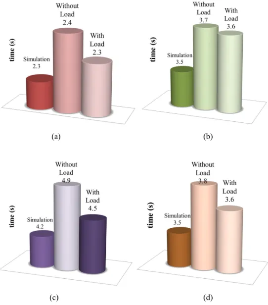
Figure 5-8 Execution time comparison for simulation, without bottle and with bottle for (a) MT (b) MD (c) MA (d) MAA. ... 65
Figure 5-9 Execution time comparison for each objective functions in x, y and z -axis (a) Simulation (b) With load. ... 66
Figure 5-10 Pareto fronts of MT-MD objective functions. ... 69
- xiv -
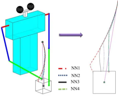
Figure 5-11 Robot arm motion for NN1, NN2, NN3 and NN4 neural controllers of MT-MD objective function. ... 69 Figure 5-12 Pareto fronts of MT-MA objective functions. ... 70 Figure 5-13 Robot arm motion for NN1, NN2, NN3 and NN4 neural controllers of
MT-MA objective function. ... 71 Figure 5-14 Pareto fronts of MD-MA objective functions. ... 72 Figure 5-15 Robot arm motion for NN1, NN2, NN3 and NN4 neural controllers of
MD-MA objective function. ... 72 Figure 5-16 Robot arm motion for f1, f2 and f3 neural controllers of single objective
function neural controllers. ... 73 Figure 5-17 Robot arm joint trajectories for (a) θ1 (b)θ2 (c) θ3. ... 75 Figure 5-18 MT-MA joint trajectories for (a) θ1 (b)θ2 (c) θ3. ... 76 Figure 5-19 Pareto comparison of two and three objective functions optimization for
(a) MT-MD(b) MT-MA (c) MD-MA. ... 77 Figure 5-20 Pareto front of MT-MD-MA objective functions optimization. ... 78 Figure 5-21 Pareto front of MT-MD-MA objective functions optimization (a) f2-f1
view (b) f3-f1 view (c) f3-f2 view. ... 79 Figure 5-22 Robot hand motion adapting NN1, NN2 and NN3 solutions. ... 81 Figure 5-23 Video capture of robot hand motion adapting NN1, NN2 and NN3
solutions. ... 81 Figure 5-24 Joint angular displacement comparison between simulation and
experiment of the robot arm (a) θ1 (b) θ2 (c) θ3. ... 82 Figure 5-25 Selected neural controllers for right hand (a) Picking motion (b) Holding
motion. ... 84
- xv -
Figure 5-26 Selected neural controllers for left hand (a) Picking motion (b) Holding
motion. ... 85
Figure 5-27 Simulation results for random goal position 1 and 2 for environment 1. ... 86
Figure 5-28 Simulation results for random goal position 1 and 2 for environment 2. ... 88
Figure 5-29 Simulation results for random goal position 1 and 2 for environment 3. ... 88
Figure 5-30 Mobile humanoid robot moving toward the table. ... 89
Figure 5-31 Experimental results for random goal position 1 and 2 (a) Environment 1 (b) Environment 2 (c) Environment 3. ... 90
Figure 5-32 Obstacle avoidance results for (a) Simulation (b) Real robot. ... 92
Figure 5-33 Trajectory comparison between simulation results and the real robot for (a) x-axis (b) y-axis and (c) z-axis. ... 93
Figure 5-34 Robot navigation (a) Simulation (b) Real environments. ... 94
Figure 5-35 Robot navigation in environment 1 (a) Simulation (b) Experiment. ... 96
Figure 5-36 Robot navigation in environment 2 (a) Simulation (b) Experiment. ... 97
Figure 5-37 Robot navigation in environment 3 (a) Simulation (b) Experiment. ... 98
Figure 5-38 Robot hand simulation. ... 100
Figure 5-39 Mobile robot approaching the table. ... 100
Figure 5-40 Spray can detection via laser range sensor and reaching motion of the robot hand. ... 101
Figure 5-41 Reaching and picking the spray can motion of the robot hand. ... 101
Figure 5-42 Comparison of the robot hand motion between simulation and experiment (GP1) for (a) x-axis (b) y-axis (c) z-axis ... 103
- xvi -
Figure 5-43 Comparison of the robot hand motion between simulation and
experiment (GP2) for (a) x-axis (b) y-axis (c) z-axis ... 104
1 INTRODUCTION
The increasing number of ageing population becomes one of the main factor for research in the field of mobile humanoid robot is still relevant and important as it can potentially be applied and used in the hospital, rehabilitation centre, elderly people centre and or in our own home. The main problem with these domestic robots is the price is too high and unaffordable by normal people. This is the reason, researches in this area are still going on and numbers of mobile humanoid robots are still being built in recent years. The main focus is to come out with the best robot that can perform domestic task, has high mobility, safe to co-exist with the human and affordable. A lot of factors and constraints have to be considered in developing a mobile humanoid ro- bot such as the safety features, robustness, flexibility, manoeuvrability, ability to understand human instructions, ability to process informations, the task performance speed and the most important aspect is the cost of building it.
Basically, a mobile humanoid robot consists of three main parts, the main body, mobile platform, vision and sensory system. Each of these parts has their own function and contribution to the developed mobile humanoid robot and need to be integrated in order to have a complete and functional system. The main body is designed to perform the manipulation task such as picking, placing, holding, pushing and moving and ob- ject. The design should consider both mechanical and electrical parts such as the
kinematics analysis, number of degrees of freedom, mechanical and electronic compo- nents and their positions, safety features and the limitation of the robot motion.
The vision and sensory system are very important in order to guide the robot while navigating in the environment and avoiding obstacles, to determine the object or obstacle size, shape and position for the robot manipulation and also for receiving in- struction from human. The last part is the mobile platform and it becomes the base for the upper body and other components such as battery and PC. The main function of the mobile platform is to navigate around the environment and moving to the desired location while avoiding obstacles.
Another important issue in developing a mobile humanoid robot is to have an op- timized arm motion when performing a specific task. A human can easily move their hand to perform a task with high speed and accuracy but for a robot to do the same task a lot of considerations need to be made. Three basic criteria in arm motions should be considered; the time, distance and speed which are very important in order to have a good performance in task execution.
1.1 Background
In performing domestics task such as cleaning, picking and carrying food or household item from one room to another, a mobile humanoid robot are required to have high mobility, and ability to manipulate object in optimized manner. There are numbers of constraints and consideration need to be made in order to perform these tasks such as unknown environment, obstacles avoidance, object recognition and ma- nipulation, the execution time, safety features and understanding human instruction.
In this thesis we investigate the performance of the proposed optimal neural con- troller in simulation environment and we verified the performance on the newly developed mobile humanoid robot. Single and multi-objective evolutionary algorithms are proposed to generate optimal neural controllers for the robot arm motion to per- form simple domestic task. Arm motion generation in dynamic environment is also considered in this thesis. The performance of evolved neural controllers is tested in the mobile humanoid robot developed in our lab.
1.2 Research Goal
The main goal of this thesis is to develop an intelligent humanoid robot able to perform several tasks. The humanoid robot selects the appropriate neural controller from a set of pre-evolved neural controllers for the specific tasks. Another objective is to apply multi-objective GA for simultaneous evolution of neural controllers.
1.3 Achievement
We have developed a humanoid robot able to generate the arm motion satisfying several objective functions. The proposed optimized neural controllers show good re- sults both in simulated and real robot implementation. In addition, arm motion generation in dynamic environment where obstacles are present is also considered.
The developed mobile humanoid robot navigates in the environment to reach the target location and performs the task.
1.4 Thesis Outline
The thesis is organized as follows; in Chapter 2, the literature review and related works are explained in details. The previous works and the current development of mobile humanoid robot research are discussed in this chapter. Chapter 3 introduces
our newly developed mobile humanoid robot. The kinematics analysis, detail design process, software architecture, mechanical and electronic components and the kinesi- ology of the robot motion are explained. The evolution of neural controllers and problem formulation are discussed in Chapter 4. Chapter 5 presents the results and performance verifications on simulated environment and on the real robot. All the findings are discussed in details. Chapter 6 concludes the thesis and discusses the fu- ture work that can be drawn on this research.
2 LITERATURE REVIEW
In the twenty-first century, the percentage of ageing population is increasing not only in the developed country and apparently in the developing country as well. Near- ly in the future, all countries will be facing similar situation although the level of intensity and time frames are varies between each countries. This scenario will lead economic, political and social problem such as extension of retirement and pension, rising medical cost and increasing demand in health care service (Kose 1997). Fig. 1- 1(a), Fig. 1-1(b) and Fig. 1-1(c) show the comparison of the ageing population of the World, Japan and Malaysia, respectively.
Statistics show that in less than 40 years, the world will have an increasing num- ber of elderly people especially in developed country such as Japan and South Korea, but in developing country such as Malaysia the problem is less critical. Fig. 1-2 shows that, Japan has the highest number of ageing population in the world. In 1990, Japan population was approximately 124 million and 12% was over 65 years and older. In 1986 the percentage is increased to 23.6% and it is estimated to be 30% in 2020. It can be read in the newspapers and reports that the number of ageing people in Japan will further increase and it is going to be 40% in 2050. This problem is getting worse with the decreasing number of birth rate and it is expected to be more than 20% reduction by 2050. This scenario will increase the needs of assisting and taking care of the elder- ly every year.
To address this problem, a variety of assistive robots have been proposed to assist the elderly in their everyday life such as eating, drinking, cleaning and for emergen- cies. The main problem with these service robots is the cost of owning them. Today, the need of having a service robot in each of the elderly house is a must. Researches in this area need to be continued in order to make the service robot more affordable and flexible.
Figure 1-1 Changes of population pyramid (a) World (b) Japan (c) Malaysia.
(a)
(b)
(c)
Figure 1-2 Age structure population by country.
Figure 1-3 Assistive mobile humanoid robot (a) TWENDY-ONE (b) ARMAR III (c) RIBA (d) Dynamaid (e) Snackbot (f) PR2.
(a) (b) (c)
(d) (e) (f)
The research and development of mobile humanoid robots has started since the era of Leonardo da Vinci (Rosheim 2006). Since then, there are numbers of humanoid robots that had been developed by private companies and universities. Among the es- tablished mobile humanoid robots that were developed are Waseda University’s TWENDY-ONE (Iwata & Sugano 2009), Karlsruhe Institute of Technology’s AR- MAR III (Albers et al. 2006), University of Bonn’s Dynamaid (Stuckler, Schreiber, et al. 2009), Snackbot from Carnegie Mellon University (Lee et al. 2009), RIBA from RIKEN-TRI (Mukai et al. 2010), PR2 from Georgia Institute of Technology (Chen et al. 2013), Pearl robot, a collaboration research from three different universities, Uni- versity of Michigan, University of Pittsburgh and Carnegie Mellon University (Pollack et al. 2002), Assistant Robot from University of Tokyo (Yamazaki et al. 2012) and Care-O-Bot from Fraunhofer Institute of Manufacturing and Automation (Schraft et al.
1998). Fig. 1-3 shows some of the developed mobile humanoid robots.
2.1 Assistive Humanoid Robots
Mobile humanoid robots have been developed for helping elderly people in their daily life activities for example assisting them with the household chores, in the hospi- tal or in a care centre. Iwata & Sugano (2009) have developed a sophisticated symbiotic robot, TWENDY-ONE which provides a physical support to the elderly.
The robot is developed to attendant the elderly in their home environment especially in the kitchen. The robot has five basics features in the design namely, safety, friendli- ness, dexterity, high power and mobility. The robot consists of a head, a pair of compact passive mechanism arms, a pair of anthropomorphic hands and omni- directional wheel. Tactile force sensors are placed on the robot body for safety when the robot is in contact with humans. A similar assistant robot, ARMAR has been de-
veloped by Karlsruhe Institute of Technology has the capability of moving from one room to another and picking a specific object commanded by the user. The robot con- sist of twenty five mechanical degrees of freedom, 4 dofs body, a pair of anthropomorphic arms with 7 dofs each, two simple grippers and 3 dofs head (Asfour et al. 2000). An improved version, ARMAR II and ARMAR III has been developed with improve hands, vision system and design. The newly developed hands, increased the capability of the robot manipulating and performing more complicated task such as opening a door and manipulating different shape household object (Asfour et al.
2006).
A household helper name Dynamaid has been developed not only for the elderly people but it can be a personal helper to human or doing our daily chores such as sweeping and cleaning. This robot has one head, an anthropomorphic arm, a gripper and four individual steerable wheels (Stuckler, Schreiber, et al. 2009; Stuckler, Grave, et al. 2009). In recent years, a new version of Dynamaid has been developed with an improved gripper design and vision system. Cosero, the improved version of Dy- namaid has the ability to perform more complicate task such as opening the refrigerator door and opening a bottle cap (Holz et al. 2013; Nieuwenhuisen et al.
2013).
In a different environment, a nursing robot system called RIBA is developed to assist medical staff and nurses in the hospital or in a care centre. RIBA is developed to perform heavy physical task that requires human contact such as transferring patient from the bed to the wheelchair and vice versa. It needs caregiver to monitor while the robot performs the task and to make sure the patient’s safety (Mukai et al. 2010). A similar robot RI-MAN, has been developed by (Odashima et al. 2006) has a similar
function as RIBA, assisting nurses in the hospital for lifting and moving the patient.
One advantage of RI-MAN is the robot utilised soft touch sensors and react to the am- plitude and location of the external forces thus increasing its safety features while in contact with human. In a similar environment, another mobile humanoid robot, PR2 is developed to assist patients or visitors in a hospital to the desired location by holding its hand. The robot has the ability to recognized the command from the users and bring them to the desired room. PR2 not only can guide human in the hospital but also can perform a domestic task such as selecting and picking a household object and opening the drawers and doors (Chen & Kemp 2011; Chen et al. 2013; Chen et al.
2010). Dario et al. (1996) proposed three type of robot in assisting patients and hu- mans in the hospitals and institutions (URMAD), assisting the elderly and disable people at home (MOVAID) and a wheelchair integrated with robot arm (IMMEDI- ATE).
Pearl is another elderly assisting robot has been developed by three different universities. This robot reminds people about routine activities such as drinking, eat- ing, taking medicine and also guiding them through the environment. Preliminary testing has been carried out at the Longwood Retirement Community Centre (Pollack et al. 2002). In a different environment, a semi-autonomous snack serving robot has been developed in Carnegie Mellon University to serve healthy snack to humans in a university building. The robot able to move around the university building and taking orders and send it ordered snack to the users. The robot has the ability to move around the university, communicate with users, understand the command and deliver the product (Lee et al. 2009; Lee & Forlizzi 2009).
Arnold is another mobile humanoid robot developed by (Bergener et al. 1999) that have one anthropomorphic arm and capable of interacting with human. The robot has the ability to move in dynamics environment, entering a room, manipulating object and avoiding obstacle. The robot has two cameras with small field of view and a wide angle view to mimic human eye. These cameras are for the robot navigation and object manipulation. A similar type of robot with one anthropomorphic arm has been devel- oped by (Natale et al. 2007). The upper torso humanoid robot is designed to have precise 3D reaching for object manipulation, where the reaching capability of the ro- bot did not rely on the arm and the head kinematics.
Another type of robot, Magilla with different capabilities of having a human sensory system has been developed by (Coelho et al. 2000). In their work the haptic and visual sensorimotor are cognitively integrated to have a human like sensory sys- tem specifically for grasping behaviour in human infant. Saika robot developed by JSK Laboratory, University of Tokyo is another robot developed for assisting human in daily activities (Konno et al. 1997). The robot has modularized features to reduce the developing cost and light weight with only eight kilogram. All the motors are kept inside the body arm and torso for better appearance. Lopes et al. (2004) has proposed a human imitating upper torso robot that can recognize and follow human motion via its vision system. The robot consists of one anthropomorphic arm that has the same de- grees of freedom as a human. The robot is developed for rehabilitation purpose.
2.1.1 System Integration
In order to perform a domestic task such as getting a bottle of juice from the kitchen or guiding humans to the desired location, numbers of considerations need to be made such as understanding the command, determining the environment, obstacles
avoidance, object recognition and manipulation, safety features and many others.
Chen & Kemp (2011; 2010) has proposed a direct contact between human and robot to guide the human from one location to another, for example leading a child by the hand or assisting nurses a hospital. A direct physical interface is introduced to enables a user to influence the robot behaviour by making contact to the robot body. Testing has been done in a real hospital with volunteered nurses to test the performance of the robot. In their work, a combination of MEKA Robotic arms, an Omni directional Segway and a linear actuator by Festo are used as complete robotic system. The robot wrist is equipped with six axis force sensor to sense the input from human or while holding their hand. A nurse robot, PEARL has been developed by (Pollack et al. 2002) for as- sisting the elderly. Two main purpose of PEARL is to remind people about routine activities such eating, drinking, bathing and taking medicine and the other function is to guide them through their environment. A high level control architecture, partially observable Markov decision process (POMDP) has been adapted in this robot.
In other work by (Stuckler, Grave, et al. 2009), a personal robot for helping household chores has been developed. The robot Dynamaid adapted four schemes for navigation namely Fast Simultaneously Localization and Mapping (FastSLAM), local- ization, path planning and safe local navigation. Holz et al. (Holz et al. 2013), has proposed global-to-local control strategy to navigate the developed robot, Cosero from the transport box to the processing place for bin picking. A rough estimation of the exact environment in the form of 2D is employed. The approximate location is navigated globally and the robot is locally aligned with the transport box and the pro- cessing place. Adaptive Monte Carlo Localization is used to estimate the robot’s pose in a given grid map using a laser range finder. A* search is applied to find the shortest
obstacles free path from the estimate position to the target location. For the arm ma- nipulation, LBKPIECE is utilised in order to maximised the performance and reduce the execution time.
2.2 Arm Motion Generation
In order to perform daily life activities, a mobile humanoid robot is required to have the ability to locate and manipulate object. Therefore, they have to perform a wide range of tasks, such as picking an object and giving it to the human, removing an unnecessary object, opening and closing the door. The wide range of robot task re- quires different robot motion strategies. In addition, because there are an infinite number of trajectories connecting the robot hand position with the goal location, the robot has to select the best trajectory and speed in order to complete the task success- fully.
Many different methods and approaches have been proposed in the past decades on humanoid robot arm motion generation. A minimum time trajectories robot arm motion has been proposed by (Sahar & Hollerbach 1986). In their work, a general so- lution is proposed to solve minimum time trajectory path which involves joint space tessellation, a dynamic time scaling and a graph search. The full dynamics of the arm movement and actuator constraints are incorporated. With these features, the arm mo- tion while avoiding obstacle can be easily generated. Flash & Hogans (1985) had proposed minimum hand jerk criteria where the position vector of the hand is defined with respect to the Cartesian coordinate system. Differentiating the position three times will define the jerk of the hand. The arm motion from its initial to the goal posi- tion is generated by minimizing the time integral of the square magnitude of jerk.
Rosenbaum et al. (1995) has proposed a similar approach of generating arm motion by
minimum angle jerk. The coordinate movement of the arm and trunk using optimiza- tion criteria defined in the joint space.
Minimum torque change criterion has been introduced by Uno et al. (1989), where control objects are the joint links plan in an intrinsic dynamic- mechanical space. The hand trajectory properties are reproduced based on the arm dynamics, pos- ture, external forces and motion duration. An improve version of minimum torque change has been proposed by (Uno, Y. Kawato, M. Suzuki 1989). In minimum com- manded torque change, the incorrect values of the inertia and viscosity as in minimum torque change have been improved. The same approach has been proposed by (Nakano et al. 1999) using representation of motor commands controlling the muscles. Kawato et al. (1990) utilized minimum torque change to produce a multi joint arm motion while avoiding obstacles and passing through points. Wada et al. (2001) has compared the performance of all four optimal theories namely minimum hand jerk, minimum angle jerk, minimum torque change and minimum commanded torque change. In his study, the minimum commanded torque change show the optimum results and has the closest trajectories to human.
In recent years, there are numbers of arm motion generation technique, Vahrenkamp et al. (2008) suggested Rapid-Exploring Random Trees (RRTs) which can adapt the number of active degree of freedom used in robot motion thus improving the performance and quality of the trajectories. The numbers of degree of freedom used are optimized using RRT. In an eight degree of freedom robot, RRT determines the optimum number of joints needed to complete the task. An improved version of RRT, Rapidly Exploring Dense Tree (RDT) has been proposed by (Vahrenkamp et al. 2011), with addition of automatic adjustment collision detection system.
Ang et al.(2009) proposed a minimum time motion planning of robot arm using Pareto based multi-objective Bees Algorithm for a SCARA robot. Four different op- erators are used to optimize the cubic splines trajectories thus minimizing the travelling time of the robot which are discrete recombination, intermediate recombina- tion, line recombination and path redistribution and relaxation.
2.2.1 Arm Motion as an Optimization Problem
During everyday task performance, humans move their arms in different ways satisfying different constraints. For example to move a cup of coffee, human arm need to move such as to minimize the acceleration in order not to spill the coffee. For more complicated tasks such as drawing a straight line or pushing a non-rigid object, the kinematics constraints such as velocity and acceleration are required to be decreased resulting in a longer execution time. Such scenarios inspired researchers to adapt the similar approach in generating robot hand motion for specific tasks.
For a robot hand to have a human like motion, similar characteristics and ap- proaches of motion generation need to be properly considered. To address this problem, a single objective optimization Genetic Algorithm (GA) for robot trajectory planning and collision avoidance has been proposed (Rana & Zalzala 1996; Wang &
Zalzala 1996; Pires & Machado 2000). Rana & Zalzala (1996) proposed an open loop minimum time planning of a two link planar robot manipulator. The optimization is done via evolutionary algorithm to have a minimum time motion and simultaneously avoiding obstacles. A similar approach of utilising genetic algorithm in searching the optimal robot manipulator path has been proposed by Wang & Zalzala (1996). In their study, the motion of six dof robotic arm is optimized in terms of minimum time. In other work by Pires & Machado (2000), GA is chosen to minimize the distance trav-
elled by a three link planar robot manipulator based on its kinematics and dynamics.
The motion generations of these works are based on direct kinematics of the robot ma- nipulator, which is proven better than motion generated using inverse kinematics by (Chen & Zalzala 1997). Based on direct kinematics of a two link planar robot manipu- lator, Kubota et al. (1997), generates robot manipulator collision free motion using virus evolutionary genetic algorithm optimizing the distance from its initial to goal position.
In recent decade, multi-objective evolution of robot arm motion generation has been proposed. Pires et al. (2007), proposed a multi objective motion generation for two and three dof planar robot manipulator optimizing two and five objective criteria.
The five chosen objectives are; minimum joint traveling distance, minimum joint ve- locity, minimum Cartesian distance, minimum Cartesian velocity and minimum energy. The robot manipulator trajectory is minimized via GA adopting direct kinemat- ics.
In other works by Ramabalan et al. (2008), two multi-objective evolutionary al- gorithms (MOEA); elitist non-dominated sorting genetic algorithm (NSGA-II) and multi-objective differential evolution (MODE) are proposed to generate the motion of two robots, Cartesian and PUMA 560. Both robot end effectors are required to do pick and place operation in the workspace avoiding three obstacles. The two objective func- tions selected to be optimized are the travelling time and consumed energy. In order to select the Pareto optimal front, normalized weighting objective function and fuzzy membership function are used. Liu et al. (2011) proposed an improved version non- dominated differential evolution (NSDE) to generate the two and three degree of free- dom (dof) planar redundant manipulator motion. Multiple objectives namely
singularity avoidance, obstacles avoidance and joint limit avoidance are chosen to be optimized. Rehman et al. (2010) have proposed MOGA for generating parallel kine- matics machine motion while considering three objectives optimization. The optimal path of the three dof parallel kinematics machine is generated optimizing the minimum electric energy used by the actuators, maximum torque and minimizing the shaking force.
In the next chapter, our developed mobile humanoid robot is discussed in terms of its kinematic analysis, mechatronics design, software, arm motion generation and the system integration.
3 MOBILE HUMANOID ROBOT PLATFORM
Most of the previously developed mobile humanoid robot are well established, having good design, robust and has the ability to perform domestics and complicated task. In this study, we developed a new upper torso mobile humanoid robot for assist- ing the elderly and disable people. It has the basic of human motion and sufficient enough to do simple task. The upper part is attached to a mobile platform for more flexibility and mobility. Mobile platform is chosen based upon the stability and its simplicity over a pair of leg (Mohamed & Capi 2012). The upper body has ten degrees of freedom hands, a pair of simple gripers and two degrees of freedom head as in Fig.
3-1.
In this chapter, the detail descriptions of the developed mobile humanoid robot are discussed in terms of its kinematics analysis, mechatronics design, software configura- tion and kinesiology of the robot movements. This robot is originally designed to assist elderly or handicap people in everyday life chores. The design of the mobile humanoid robot are considering the safety features, ability to navigate throughout the environment, obstacles avoidance, ability to perform simple manipulation, position determination and object recognition (Mohamed & Capi 2012). Later in this thesis, the proposed neural controllers will be implemented on this mobile humanoid robot to in- vestigate its performance.
3.1 Kinematics Analysis
The robot hand positioning is very important in order to perform a task with high accuracy and stability. Proper kinematics analysis is required to determine the current and goal position of the robot hand. The direct and inverse kinematics analysis of the robot arm is discussed in this section and in Appendix A.
3.1.1 Denavit-Hartenberg (DH) Parameters
There are many methods to determine the direct kinematics of a robot arm and one of the most established methods is Denavit-Hartenberg (DH) analysis. This is the reason DH analysis is utilized in this thesis to determine the direct kinematics of the robot hand. In DH analysis, the homogeneous transformation matrix can be deter- mined, which specifies the position and orientation of the robot hand with respect to the base as in Fig. 3-1 (Sciavicco & Siciliano 2001; Jazar 2007; Asada & Slotline 1986; Spong et al. 1993).
Figure 3-1 Coordinate frame of the robot upper body.
Implementing DH convention and following the procedures, the D-H parame- ters for the robot hand assigned frames are defined in Table 3-1. The transformation equation of the DH analysis is as follows;
−
−
=
= − ′
−
1 0
0 0
cos sin
0
sin sin
cos cos
cos sin
cos sin
sin cos
sin cos
1 1
i i
i
i i i i i
i i
i i i i i
i i
i i i i i
i d
a a A
A
T α α
θ α
θ α
θ θ
θ α
θ α
θ θ
(1)
Table 3-1 D-H Parameters.
Joint, i ai αi di θi
OA 0 900 d1 θ1
B a1 0 0 θ2
C a2 0 0 θ3
D 0 0 0 Gripper
By substituting these parameters into equation (1), the transformation matrices T1 to T4 can be shown as follows:
= −
=
1 0
0 0
0 1 0
0 cos 0
sin
0 sin
0 cos
1 1 1
1 1
1 0
1 A d
T θ θ
θ θ
−
=
=
1 0
0 0
1 0 0
sin 0
cos sin
cos 0
sin cos
1 2 2 2
2
2 2 2
2
2 1
2 d
a a A
T θ θ θ
θ θ
θ
−
=
=
1 0
0 0
0 1
0 0
sin 0
cos sin
cos 0
sin cos
3 3 3
3
3 3 3
3
3 2 3
θ θ
θ
θ θ
θ
a a A
T
=
=
1 0 0 0
0 1 0 0
0 0 1 0
0 0 0 1
4 3
4 A
T
The robot hand position can be determined based on the forward kinematics equation obtained from the transformation matrix as follows;
( )
( )
+ +
+
−
−
+
−
=
=
1 0
0 0
0 3 23 2 2 1
23 23
2 2 23 3 1 1 23 1 23 1
2 2 23 3 1 1 23 1 23 1
3 3 2 1 0
4 S C a S a S d
C a C a S C S
S C
S
C a C a C S S C C
C A A A A
T (2)
where C1 is cosθ1, C2 is cosθ2, S1 is sinθ1, S2 is sinθ2, C23 is cos(θ2+θ3) and S23 is sin(θ2- +θ3). The first three columns represent the orientation of the end effector whereas the last column represents the position of the robot hand (Fig. 3-1) as in equation (3) be- low.
( )
( )
[ ]
( )
[
2 2 3 2 3]
1
3 2 3 2 2 1
3 2 3 2 2 1
cos cos
cos
cos cos
sin
sin sin
θ θ θ
θ
θ θ θ
θ
θ θ θ
+ +
=
+ +
=
+ +
+
=
a a
P
a a
P
a a
d P
z y x
(3)
3.1.2 Inverse Kinematics
The direct kinematics analysis in the previous section established a functional relationship between the joint angle and the robot hand position and orientation. In in-
verse kinematics analysis, the joint angles are determined based on the given position of the robot arm. Inverse kinematics is very important for determining the current ro- bot hand position and goal position to perform a specific task. In this research, a geometric approach is utilised to determine the inverse kinematics of the robot arms.
Referring Fig. 3-2, the three joint angles of the robot arm are determined using equa- tion (4), equation (5) and equation (6) for shoulder, upper arm and lower arm respectively. The detail analysis of the robot kinematics is shown in Appendix A.
= −
z y
P
1 P
1 tan
θ (4)
( ) ( )
( )
+ − − +
= −
3 2
2 3 2 2 2 1 2
1
3 cos 2
a a
a a d P Pd x
θ (5)
( )
+
±
−
= − −
s a a P
d P
d
x 1 1 2 3 3
1 2
cos cos
tan θ
θ (6)
Figure 3- 2 Inverse kinematics analysis of the robot hand.
These equations are utilised in the MATLAB program for the robot arm simu- lations and on the real robot. The same approach is done for the left hand with a minimum modification of the coordinate system. The detail explanation and derivation of the robot hand’s inverse kinematics are discussed in (Mohamed & Capi 2012).
3.2 Mechatronics Design & Hardware Architecture
The development process of the mobile humanoid robot is discussed in this sec- tion, in terms of the mechanical design, mechatronics systems and the software architecture of the robot system. The robot system is divided into two main parts, the upper body and the moving platform. The upper body designed is mainly for object manipulation and recognition, while the mobile platform is utilised for the robot navi- gation and obstacles avoidance.
3.2.1 Upper Body
The upper body of the mobile humanoid robot is consisting of a head, a pair of arms and space for all the electronics parts and components. The initial design of the upper part is done using Solidworks to make sure the kinematics motion of the hands is according to the developed mathematical model and the position of all the electronic components are well place in the system. Each component is drawn separately as components and assembled as a part. Most of the design, fabrication and assembly processes are done in the lab and only the shoulder base part is done in the workshop.
All the DC motors utilized to actuate the joints are aligned in series and kept inside the arm and main body for higher stability while in motion and better appear- ance. A pair of harmonic drives is attached to the shoulders for smooth motion without gear backlashes. Two grippers are attached to both arms for simple manipulation and
they are actuated by servo motors. Aluminium plates and rods are chosen for most of the robot parts due to its light weight and high strength properties. Initially, plastic ma- terial is chosen for the robot arms cover, but in the final design, combinations of two L-shape plate are chosen. These covers not only secure the electronics components inside the arm structures but it is also preventing the arm from twisting while in mo- tion or holding an object. Fig. 3-3 and Fig. 3-4 show the arm design assembly and the real robot arm for right and left hand, respectively.
Figure 3-3 Right hand design of the mobile humanoid robot.
Figure 3-4 Left hand design of the mobile humanoid robot.
Another important aspect in robot design is the safety features especially when interacting and performing task in human environment. It is a must for a robot to have high safety features in order to co-exist with humans. Currently, an emergency stop button is placed at the back of the upper body for emergency cases and stopping the robot instantly.
3.2.2 Mobile Platform
The mobile platform is powered by two AC motors with 24V battery, a control- ler and base for the upper body. The battery, PC, AC motors, laser range finder (LRF) and the upper body is placed on this platform as in Fig. 3-5. The mobile platform has a maximum speed of 1 ms-1 and it can be easily controlled using MATLAB (PC). LRF1 is place at the front lower part of the robot for object detection and obstacles avoid- ance. The upper body is placed in the middle of the platform to increase its stability.
Figure 3-5 Mobile platform.
Figure 3-6 DC Motors and motor drivers.
3.2.3 Electronic Components
3.2.3.1 DC Motors
Six Maxon brushless DC motors and six MD30B DC motor drivers are used in this system. These DC motors moves the robot shoulders, upper arms and lower arms as in Fig. 3-6. The motor drivers are very important in order to control the speed of the DC motor. Ability to control the motors at low speed is very important criteria in order to have a stable and smooth motion hand trajectory. Different gear ratios of DC motor are selected based on the requirement of each joints. These motors can be powered by a 9V power supply or a battery.
3.2.3.2 AC Motors
For smooth robot navigation, two Yamaha AC motors are chosen and they are powered by 24V battery as in Fig. 3-7. Smooth motion is very important for the stabil- ity of the robot, thus the robot will have low vibration while navigating.
Figure 3-7 AC Motors.
3.2.3.3 Servo Motors
The robot hand motion and the head movement utilised eight servo motors as in Fig. 3-8. Two servos are for simple gripping, four servos for roll and pitch motion of the robot hands and two servos for the robot head pan and tilt. Servos are selected for its simplicity, light weight and easy to control. The grippers are developed in the lab and have the ability to do a simple grasping.
Figure 3-8 Servo motors.
Figure 3-9 Laser range finder (LRF).
3.2.3.4 Laser Range Finder (LRF)
Robot navigation is almost impossible without the laser range finder (LRF).
Two set of Hakuyo LRF (URG-04LX-UG01) are used, one for robot navigation around the environment and the other is for object position determination on the standard table height. The LRF can scan from 2 cm to 560 cm in distance with 2400 range. The accuracy of the measured distance is within 3% at 100 ms/scan scanning time and the scanning resolution is 0.360. The LRF has light weight features weighing only 160 g and powered by 5V voltage supply. The position of the LRFs is shown in Fig. 3-9.
Fig. 3-10(a) shows obstacles detection for mobile platform’s LRF. The scan- ning angle is set to be from 100 to 1700 with obstacle detection within 50cm to 100 cm.
If the obstacles are detected on the right area the mobile platform will steer to the left and vice versa. The obstacles detection via LRF can be determined using simple equa- tions as follows:
θ θ
cos sinmin min
min min
d x
d y
=
=
(7)
where dmin is the shortest distance determined using LRF.
Fig. 3-10(b) shows the object position determination on a standard table height by the robot. Utilizing the second LRF, the minimum distance of the object on the ta- ble can be detected and by applying equation (7), the position of the object on the table can be determined. The function of this LRF is not only for determining the object to be manipulated on the table but also for detecting the obstacle in the workspace area with the assistance of the camera.
Figure 3-10 (a) Obstacle detection via LRF1 (mobile platform) (b) Spray can detec- tion via LRF2 at table height (upper body).
(a)
(b)
3.2.3.5 Potentiometers
In order to determine the robot arm joint angles, six potentiometers are used.
These angles are utilized to determine the robot hand positions in Cartesian space.
Two type of potentiometers used are shown in Fig. 3-11. The actual joint angles are acquired directly from these potentiometers thus the minimum and maximum angular speed of each joint can be determined. The joint angular speeds are used in the simula- tions and experiments to generate the kinematics properties of the robot hand.
\
Figure 3-11 Potentiometers.
3.2.4 Software Architecture
3.2.4.1 MATLAB Simulation
Before the optimal neural controllers can be adapted on the simulator and on the real robot, the weight functions of both SOGA and MOGA are generated in MATLAB environment using the developed toolbox. The simulator of the mobile hu- manoid robot is also developed using MATLAB as in Fig. 3-12(a). The generated neural controller using SOGA and MOGA will be implemented in this environment to
verify the performance before it can be implemented on the real robot. MATLAB is chosen based on its robustness and capability to solve complicated calculation, data acquisition and manipulation. Other advantage of MATLAB is the ability to interact with the cameras, robot controller and mobile platform in real time. A special graph- ical user interface (GUI) has been designed that allow user to control the robot manually as in Fig. 3-12(b). Each joint can be moved separately and simultaneously via this GUI.
The robot maximum and minimum motion for each joint has been included in the main program to have additional safety features while the robot is in motion. These features are very important in order to make sure that all the mechanical joints and electronics components are not easily damage.
3.2.5 System Integration
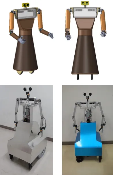
Fig. 3-13 shows the complete system and the developed mobile humanoid ro- bot. The key specifications the mobile humanoid robot is shown below:
• Arm length – 54 cm
• Total height – 134 cm
• Total length – 67 cm
• Robot platform width – 52 cm
• Upper body weight – 14 kg
• Mobile platform weight – 16 kg
• Maximum moving speed 1 m/s
Figure 3-12 (a) Robot arm simulator (b) GUI.
(a)
(b)
Figure 3-13 Developed mobile humanoid robot.
The integrated mobile humanoid robot system and the position of each electron- ics components and mechanical parts are shown in Fig. 3-14. Each component and their functions that have been discussed in the previous section are assembled to have a complete system. The mobile platform, the upper, both cameras and both laser range finders are control directly from the PC via USB connector. This complete system will be utilised to compare the performance of the generated neural controller using single
objective and multi-objective genetic algorithm. Eventhough the developed system is incomparable with the established robot platform; our robot has the ability to adapt the proposed neural controllers and show good performance.
Figure 3- 14 Integrated system.
3.3 Kinesiology of the Robot Motion
Human motions consist of six basic movements namely, flexion, extension, ab- duction, adduction, supination and pronation. Flexion is a bending movement relative to reference position and extension is a straightening movement as the joint return to is reference position. Abduction is movement away from the body centreline and the re- turn motion is called adduction. Supination is the movement of the forearm where the palm rotates forward and pronation is when it returns back to the reference position (Hamill & Knutzen 2003; Hamilton et al. 2008). We adapted these movements on the
(a) (b)
developed robot with limited available joints. The movements are divided into three section; head, arm and hand.
The two degrees of freedom robot head not only capable of executing flexion and extension movement but also left and right rotations as in Fig. 3-15. These movements are very important for robot navigation and object recognition. Two servo motors are used to actuate both pan and tilting motion.
Figure 3- 15 Robot head movements.
Figure 3- 16 Robot arm movements.
Fig. 3-16 shows the robot arms movement of flexion, extension, abduction and adduction. This motion is important to determine the maximum reach of the robot hand in the simulated and working environment. For simple manipulation by the robot hand, flexion, extension, pronation and supination movements are important and it is shown in Fig. 3-17 and Fig. 3-18, respectively.
By knowing the kinesiology of the robot arm motions, the safety distance and the effective working area can be determined and implemented in the robot program.
The upper and lower limit of all the joints can be set and it is shown in Appendix B.
Figure 3-17 Robot hand flexion and extension movements.
Figure 3-18 Robot hand supination, semiprone and pronation movements.
4 EVOLUTION OF NEURAL CONTROLLERS
In order to find one or more feasible solutions related to one or more objective, optimization is needed to make a system more effective and functional. Evolutionary algorithm utilised both neural network and genetic algorithm is chosen based on the performance and robustness of the technique. Two types of optimizations have been adapted in this thesis, single objective and multi objective optimization. In our imple- mentation, both category of optimization are applied to the simulation and the mobile humanoid robot. Before the neural controller can be generated, the tasks for the robot arm have to perform need to be determine and it will be discussed in the next section.
4.1 Problem Formulation
In performing a domestic task such as picking and placing a bottle, removing the thrash, pushing a box or avoiding obstacles, the humanoid robot arm trajectory and speed must be carefully selected in order to complete the task successfully. Therefore, in each stage of task performance, the main problem is what trajectory and how the moving speed must change connecting the robot hand and goal positions. The human- oid robot has to move the hand (object) from the initial to the goal position, which is connected with an infinite number of trajectories and motion velocities. The main problem is how to determine the joint trajectories in order to reach the goal position in minimum possible time or distance.
4.1.1 Robot Arm Tasks Selection
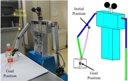
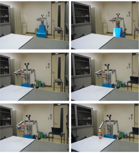
In this thesis, the mobile robot humanoid robot is required to perform three dif- ferent tasks. In the initial stage of this research, a task of placing a bottle on a table from a holding position is chosen as shown in Fig. 4-1. This motion is chosen to verify the performance of our mobile humanoid robot adapting the proposed optimal neural controllers. In this task, the performance of single and multi-objective arm motion generation are tested and compared.
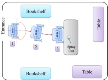
In the next task, the mobile humanoid robot has to move from the lab entrance toward the table with the assistance of webcam and laser range finder for simple navi- gation and obstacle avoidance as in Fig. 4-2. The robot utilized the camera in order to get in the center of the table (from position 1 to 2). With the assistive of the LRF1 (Fig. 3-10(a)), the robot moves near to the table and stop at the desired distance. For this experiment, the table height is set to be 74 cm, which is the standard range height of a normal table.
Figure 4-1 Task 1: Placing a bottle on the table.