INTERCALATION KINETICS, AND NOVEL PREPARATION METHOD FOR POLYMER
NANO-COMPOSITES
MARCH 2013
DOCTOR OF ENGINEERING
TOMOTAKA SAITO
TOYOHASHI UNIVERSITY OF TECHNOLOGY
i
INTERCALATION KINETICS AND NOVEL PREPARATION METHOD FOR POLYMER NANO-COMPOSITES
Abstract
In the last two decades, polymeric nano-composite is one of the fast-growing category of material science on a worldwide basis. Getting attention on importance of nano-technology today, some results of polymeric nano-composites have been industrialized in many countries.
Polymer nano-composite consists of polymer matrix and nano-sized filler which has at least one of the dimension is of the order of a nano-meter, and the filler is dispersed into polymer matrix in nano-scale. First report of the material was from Toyota Central Research & Development Laboratories’ (TCRDL) group for polyamide 6/clay nano-composite via in-situ polymerization of -caprolactam, in which alkylammonium-modified montmorillonite (MMT) was thoroughly dispersed in advance.
The resulting composite with loading only 4.2 wt% clay possessed a doubled modulus, a 50%-enhanced strength, and an increase in heat distortion temperature of 80 oC as compared to that of neat polyamide 6.
The main reason for these improved properties in nano-composites is interfacial interaction between matrix and OMLF as opposed to conventional composites. A few weight percent of OMLF are properly dispersed throughout the matrix thus creates a much higher surface area for polymer-filler interfacial interactions than do conventional micro-composites. In case of the nano-particle use as nano-filler, the key technnology is dispersion technique, in other words, preparation method for nano-composite materials.
Continued progresses in nano-scale controlling have contributed to the rapid development of polymer/OMLF nano-composites. Three types of main approaches for the
ii
of polymer or pre-polymer from solution (solution cast), and melt compounding.
In case of preparation for non-polar or weak polar polymer-based nano-composites, compatibilizer was added through melt compounding process to apply shear stress to OMLF layers. In other words, non-polar polymer-based nano-composite preparation without compatibilizer is not possible through above three methods. To solve this issue, we should investigate a novel preparation method, from industrial point of view, which is able to apply to the practical industrial production system.
The main objective of this study is to bring out the factors that concerned with nano-composite formation and to feed back these factors for the preparation of the polymer nano-composite. For this purpose, we investigated fundamental study of the phase transition of the cationic surfactant located at the interlayer space in montmorillonite, and examined the intercalation behavior of the small molecules by using various types of nano-fillers, which have a strong impact on the explanation for the intercalation kinetics. We chose an optimal OMLF and conducted the Poly(p-phenylenesulfide) (PPS)-based nano-composites preparation with and/or without shear processing. Furthermore, we have developed more innovative compounding process, i.e., solid-state processing, to delaminate the stacked-and-layered filler in the polymer matrix. And we adopted non-polar polymer as matrix to confirm the processing ability, and to investigate the effect of polarity of the matrix polymer on solid-state processing. The present thesis consists of the following 6 chapters.
In Chapter 1, the previous reported papers are totally reviewed about the polymer nano-composite studies and preparation methods for the materials, from which the unsolved problems are picked up and the motivation of the present research will be clarified.
iii
In Chapter 2, we investigated nonisothermal order-disorder transition behavior of alkylammonium ions in nano-confined space i.e., interlayer space of MMT, compared with crystallized dioctadecyl dimethyl ammonium bromide (DC18DM-Br) through temperature modulated differential scanning calorimeter, wide-angle X-ray diffraction (WAXD), and Fourier transform infrared spectroscopy (FTIR).
In Chapter 3, we investigated the intercalation behavior of small molecules, as a model compound for PPS, into various OMLFs interlayer evaluated from WAXD analysis. In the first part of Chapter 3, the effect of miscibility between small guest molecules and intercalants on the basis of DSC analysis was investigated. After that, the intercalation behavior of the molecules into the various types of OMLFs was discussed. In the remaining part, we chose an optimal OMLF and conducted the PPS-based nano-composites preparation with and without shear processing.
In the first part of Chapter 4, we discussed intercalation behavior with various polymers and OMLFs prepared by melt compound. The results show same trends as small molecules investigated in Chapter 3. In latter part, novel preparation methods, solid-state processing, to improve nano-filler dispersion and to delaminate the stacked-and-layered filler in PPS matrix was conducted. From the results, effectiveness of solid-state processing is clearly showed.
In Chapter 5, we also challenged to prepare non-polar polymer based nano-composite. It is considered that preparation for non-polar polymer-based nano-composite is difficult because polarity of matrix polymer is very important for nano-filler dispersion. Fortunately, we successfully prepared polypropylene/OMLF nano-composite with solid-state processing. In this study, two thresholds during solid-state processing were found for OMLF dispersion.
iv
Chapter 6.
****************
In this way the present thesis has revealed the nonisothernal odred-disorder transition in nano-confined space and intercalation behavior of the small molecules and various polymers into OMLF interlayer space. And novel preparation method for polymer nano-composites was developed. Even though, matrix is non-polar polymer, nano-composite was formed through the processing without adding compatibilizer. In this way, the present research is believed to contribute to the development of polymer nano-composite science and industry significantly.
v Contents
Page
Chapter 1 General Introduction 1
1-1 Background 1
1-2 Layered nano-filler 2
1-2-1 Structure and Properties 2
1-2-2 Organophilic Modification 5
1-3 Preparative methods for PLF nano-composites 7
1-3-1 Intercalation of polymer or pre-polymer from solution (solution cast method) 11 1-3-2 In-situ intercalative polymerization method 11
1-3-3 Melt intercalation method 11
1-4 Structure and Characterization of PLF nano-composites 13
1-4-1 Structure of PLF nano-composite 13
1-4-2 Characterization of PLF nano-composites 16
1-5 Matrix polymers 17
1-6 Scope of this thesis 20
References 23
Chapter 2 Nonisothermal Order-Disorder Phase Transition of Alkylammonium Ions in Nano-confined Space 2-1 Introduction 27
2-2 Experimental Section 30
2-2-1 Materials 30
2-2-2 Characterization methods 31
vi
2-3 Results and Discussion 33
2-3-1 DSC scan and crystalline structure 33
2-3-2 Temperature dependence of ordered structure development 38
2-3-2 Ordering kinetics and crystallization kinetics 43
2-4 Conclusions 55
References 56
Chapter 3 Intercalation of Diphenyl sulfide into Nano-galleries and Preparation of Poly(p-phenylenesulfide)-based Nano-composites 3-1 Introduction 58
3-2 Experimental Section 60
3-3 Results and Discussion 63
3-3-1 Intercalation of DFS molecules into nano-galleries 63
3-3-2 Effect of surface charge density on intercalation 66
3-3-3 PPS-based nano-composite formation 67
3-4 Conclusions 75
Note and References 76
Chapter 4 Poly(p-phenylenesulfide)-based Nano-composite Formation: Delamination of Organically Modified Layered Filler via Solid-state Processing 4-1 Introduction 77
4-2 Experimental 80
4-3 Results and Discussion 82
4-3-1 Intercalation behavior between various polymers and OMLFs 82 4-3-2 PPS-based nano-composites formation with or without shear compounding 87
vii
Page
4-3-3 PPS-based nano-composite formation via solid-state processing 89
4-3-3-1 Variation of WAXD profiles 89
4-3-3-2 Morphology 93
4-4 Conclusions 100
References 101
Chapter 5 Polypropylene-based Nano-composite Formation: Delamination of Organically Modified Layered Filler via Solid-state Processing 5-1 Introduction 103
5-2 Experimental Section 106
5-3 Results and Discussion 108
5-3-1 Solid-state processing with alumina mortar 108
5-3-2 Solid-state processing with internal mixer 119
5-4 Conclusions 124
References 125
Chapter 6 Summary and Conclusions 127
List of Publications 131
List of Presentations 132
viii
C
CEC cation exchange capacity
CPS critical particle size
C12TPP n-octyl tri-phenyl phosphonium C16TBP n-hexadecyl tri-n-butyl phosphonium C18Me2Bz octadecyl benzyl di-methyl ammonium
C18TM octadecyl tri-methylammonium
D
DC18DM dioctadecyl dimethylammonium
DC18DM-Br dioctadecyl dimethyl ammonium bromide
DFS diphenyl sulfide
F
FFT fast Fourier transform
FTIR Fourier transform infrared spectroscopy FWHM full width at half maximum
H HDT heat distortion temperature
HTO layered titanate
M
MMT montmorillonite O
ODA octadecyl ammonium
OMLF organically modified layered filler P
PBS poly(butylenes succinate)
PEO polyethylene oxide
PES sulfonated poly(ethylene terephthalate) copolymers
ix
PLA poly(L-lactide)
PLF polymer/layered filler
POM polarized optical microscope PP polypropylene PP-g-MA maleic anhydrate grafted polypropylene PPS poly(p-phenylenesulfide)
PVA polyvinyl alcohol
PVDF poly(vinylidene fluoride)
Q
qC14(OH) N-(cocoalkyl)-N,N-[bis(2-hydroxyethyl)]-N-methyl ammonium S
sc-CO2 supercritical CO2
SMA poly[styrene-co-(maleic anhydride)]
SSSP solid-state shear pulverization syn-FH synthetic fluorine hectorite T
TCRDL Toyota Central Research & Development Laboratories TEM transmission electron microscope
TGA thermogravimetric analysis
TMDSC temperature modulated differential scanning calorimeter W
WAXD wide angle X-ray diffraction
Chapter 1
General Introduction
Chapter 1
1 1-1. Background
In the last two decades, polymeric nano-composite is one of the fast-growing category of material science on a worldwide basis. Getting attention on importance of nano-technology today, some results of polymeric nano-composites have been industrialized in many countries [1, 2].
Polymer nano-composite consists of polymer matrix and nano-sized filler which has at least one of the dimension is of the order of a nano-meter, and the filler is dispersed into polymer matrix in nano-scale. First report of the material was from Toyota Central Research &
Development Laboratories’ (TCRDL) group for polyamide 6/clay nano-composite via in-situ polymerization of -caprolactam, in which alkylammonium-modified montmorillonite (MMT) was thoroughly dispersed in advance [3-7]. The resulting composite with loading only 4.2 wt%
clay possessed a doubled modulus, a 50%-enhanced strength, and an increase in heat distortion temperature (HDT) of 80 oC as compared to that of neat polyamide 6.
Of particular interest is a recently developed nano-composite technology consisting of a polymer and organically modified layered filler (OMLF) because they often exhibit remarkably improved materials properties including not only high muduli [4, increased strength and heat resistance [8, but also decreased gas permeability [4 flammability [9], and increased biodegradability of biodegradable polymers [10] as compared with those of the virgin polymers [11.
The main reason for these improved properties in nano-composites is interfacial interaction between matrix and OMLF as opposed to conventional composites. A few weight percent of
2
OMLF are properly dispersed throughout the matrix thus creates a much higher surface area for polymer-filler interfacial interactions than do conventional micro-composites [12].
1-2.Layered nano-filler 1-2-1.Structure and Properties
Montmorillonite (MMT), hectorite, and saponite are the most commonly used layered nano-filler for preparing polymer nano-composite, and these minerals are classified to smectite type clay. Smectite consists from tetrahedral sheet which is like hexagonal mesh by shearing three oxygen atoms on SiO2 tetrahedron, and octahedral sheet which shear edge line of the octagon. The octagon is made from six O atoms or OH groups which are on edge of the shape, and Al or Mg takes position in the octagon. Smectite type clay is called 2:1 type clay mineral because the mineral consists from two tetrahedral sheets and one octahedral sheet (Fig.1-1a).
The layer thickness is around 1 nm and the lateral dimensions of these layers may vary from 30 nm to several microns and even larger depending on the particular layered silicate. Stacking of the layers leads to a regular van der Waals gap between the layers called interlayer or gallery.
Isomorphic substitution within the layers (for example, Al3+ replaced by Mg2+ or by Fe2+, or Mg2+ replaced by Li+) generates negative charges that are counterbalanced by alkali and alkaline earth cations situated inside the galleries. The type of layered silicate is characterized by a moderate surface charge (known as cation exchange capacity (CEC), and generally expressed by mequiv/100g). This charge is not locally constant as it varies from layer to layer and considered as an average value over the whole crystal. Layered silicates take two types of
Chapter 1
3
structure, i.e., tetrahedral-substituted and octahedral substituted. In the case of tetrahedral substituted layered silicates the negative charge is located on the surface of the silicate layers, and hence, the polymer matrices can react with tetrahedral-substituted silicate more readily compared to octahedral-substituted. And these cations are easily exchange to other cations.
Interlayer space of the tetrahedral-substituted mineral is expanded by the exchanged cations and the variations are determined by type and alignment of the ions. Chemical formula and schematic images of montmorillonite (MMT), one of the natural smectite, are shown in Table 1-1 and Figure 1-1, respectively [13, 14].
Natural mica has larger layer charge density comparison with smectite and no swellable property because interlayer cation, K+, is captured in hexagonal hole on bottom face of the tetragonal sheet. On the other hand, some synthetic mica which is changed interlayer cation K+ to Na+ or Li+ and has lower layer charge density compared to natural mica, is given swellable ability. The synthetic mica is also called swelling mica, and OH groups on layer edge are changed to fluorine. And interlayer cations in the synthetic fluorine mica are able to exchange to other cations as MMT. Crystal structure and chemical formula of synthetic fluorine hectorite (syn-FH), one of the synthetic mica, is shown in Figure 1-1a and Table 1-1, respectively.
Chemical formula of potassium titanate is represented as K2O∙nTiO2 and the chemical compounds takes different n values. 4-potassium titanate, the value of n is four, forms layer structure and has K+ as interlayer cations. The K+ cation is exchangeable to other organic/inorganic cation. [15, 16] The characteristic parameters and structure of layered titanate (HTO) used in this study are shown in Table 1-1 and Figure 1-1b, respectively.
4
Figure 1-1. Crystal structure of (a) syn-FH and MMT and (b) HTO.
Mg2+
Na+ O F Si syn-FH
Na+ O OH Al3+, Mg2+
Si MMT tetrahedral
tetrahedral octahedral 0.98 nm
0.96 nm (syn-FH)
(MMT)
TiO6 octahedral
H3O+ or K+
0.374 nm (a)
(b)
Chapter 1
5 Table 1-1. Characteristic parameter of nano-fillers
Parameters HTO syn-FH MMT
Chemical formula H1.07Ti1.73O3.95・0.5H2O Na0.66Mg2.6Si4O10(F) 2 Na0.33(Al1.67Mg0.33) Si4O10(OH) 2
Particle size / nm ~100-200 ~100-200 ~100-200
BET area / m2/g ~2400 ~800 ~700
CECa) / meq/100g ~200 ~120 ~90
Surface charge/
e-/nm2 1.26 0.971 0.780
Density /g/ml 2.40 2.50 2.50
Refractive index
(n20D) 2.3 1.55 1.55
pH 4-6 9-11 7.5-10
a)Methylene blue adsorption method.
There are two particular characteristics of layered fillers that we generally consider in polymer/layered filler (PLF) nano-composites. The first is the ability of the particles to disperse into the individual layers. The second characteristic is the ability to fine-tune their surface chemistry through ion exchange reactions with organic and inorganic cations. These two characteristics of layered filler in a particular polymer matrix depend on the interlayer cation.
1-2-2. Organophilic Modification
Any simple physical mixture of a polymer and layered filler does not form a nano- composite. This situation is analogous to polymer blends, and in most cases separation into discrete phases normally takes place. In immiscible systems, which typically correspond to the more conventionally filled polymers, the poor physical interaction between the organic and the
6
inorganic components leads to poor mechanical and thermal properties. In contrast, the strong interactions between the polymer and the layered filler in PLF nano-composites lead to the organic and inorganic phases being dispersed at nano-meter level. As a result nano-composites exhibit unique properties not shared by their micro counterparts or conventionally filled polymers.
Pristine layered fillers usually contain hydrated Na+ or K+ ions [15, 17]. Obviously, in this pristine state layered silicates are only compatible with hydrophilic polymers, such as polyethylene oxide (PEO) [18-23], polyvinyl alcohol (PVA) [24, 25] etc. To render layered silicates compatible with other polymer matrices, the layers must convert the normally hydrophilic surface to organophilic, which makes the intercalation of many engineering polymers possible. Generally, this can be done by ion-exchange reactions with cationic surfactants including primary, secondary, tertiary, and quaternary alkylammonium or alkylphosphonium cations. The role of alkylammonium or alkylphosphonium cations on the layer surfaces is to lower the surface energy of the inorganic host and to improve the wetting characteristics with the polymer matrix, and results in a larger interlayer spacing. It can evaluate that about 100 alkylammonium salt molecules are localized near the individual layers (~8×10-15 m2) and active surface area is ~800 m2/g. Additionally, the alkylammonium or alkylphosphonium cations could provide functional groups that can react with the polymer matrix or in some cases initiate the polymerization of monomers to improve the strength of the interface between the inorganic layer and the polymer matrix [26, 27].
Chapter 1
7
Traditional structural characterization to determine the orientation and arrangement of the alkyl chain involves primarily by the use of wide angle X-ray diffraction (WAXD). Depending on the packing density, temperature and alkyl chain length, the chains were thought to take interdigitated layer structure, and the structure is controlled by surface charge density of the layered filler and molecular size of the organic cations [15]. Vaia and Giannelis [28] have shown that alkyl chains can vary from liquid-like to solid-like, with the liquid-like structure dominating as the interlayer density or chain length decreases (Figure 1-2), or as the temperature increases. They used Fourier transform infrared spectroscopy (FTIR), because of the relatively small energy differences between the trans and gauche conformers. The idealized models described earlier assume all trans conformations. In addition, for the longer chain length surfactants, the surfactants in the layered silicate can show thermal transition akin to melting or liquid-crystalline to liquid like transitions upon heating. The molecular models for some representative organic cations are shown in Figure 1-3. The molecular dimensions of the intercalants were determined by using a molecular dynamics program (MM2 in Quantum CAChe, Fujitsu Ltd.), taking van der Waals radii into consideration. Optimization of the structure is based on minimization of the total energy of the molecular system.
1-3. Preparative methods for PLF nano-composites
After TCRDL group reported the marked improvements in the mechanical and physical properties, studies on polymer/OMLF nano-composites have been extended to various other polymer systems, such as polystyrene [29-31, epoxy resin [32, polypropyrene [33, 34,
8
Figure 1-2. Alkyl chain aggregation models: (a) short chain lengths, the molecules are effectively isolated from each other, (b) medium lengths, quasi-discrete layers from with various degrees of inplane disorder and interdigitation between the layers and (c) long lengths, interlayer order increases leading to a liquid-crystalline polymer environment. Open circles represent the CH2 segments while cationic head groups are represented by filled circles [28].
(a) (b) (c)
Chapter 1
9
Figure 1-3. Calculated structure of (a) dioctadecyl dimethylammonium (DC18DM), (b) hexadecyl tributylphosphonium (C16TBP) and (c) octadecylammonium (ODA).
(a)
(b)
(c)
10
poly(ethyrene terephtarate) [35, poly(-caprolactone) [36, 37, polyurethanes [38, and polyimides [39with carbon nano-tube [40-42], silica nano-particle [43-45], polyhedral oligomeric silsesquioxane: POSS [46-48] and so on. However, some of these polymers have not been achieved sufficient dispersion of the nano-fillers. It needs detail studies on the interaction between polymer and nano-filler, intercalation, and/or dispersion throughout preparation process in order that obtain well dispersed nano-composites.
Particle size of filler is very important factor. Generally, powder is changed the properties on three particle size thresholds, called critical particle size (CPS). First CPS is around 100 m, and particle over the size has stable surface, and particle-particle interaction is almost lost.
Second CPS is appeared about 1 m, and the particle size between first and second CPS is easy for handling, mechanical pulverization and particle size control. Third CPS is around 100 nm, and the particle below 100 nm size is called nano-particle. The specific surface area of the nano-particle dramatically increases and the surface effect appears strongly. Additionally, new properties and functions are generated, and especially less than a few nm size particles, quantum effect is appeared on the nano-particles. However, strengthen particle-particle interaction on the nano-particle causes particle agglomeration which lost advantages of the nano-particle. In case of the nano-particle use as nano-filler, the key technology is dispersion technique, in other words, preparation method for nano-composite materials.
Continued progresses in nano-scale controlling have contributed to the rapid development of polymer/OMLF nano-composites [49]. Three types of main approaches for the polymer nano-
Chapter 1
11
composite preparation are reported, i.e., in-situ polymerization [3-7], intercalation of polymer or pre-polymer from solution (solution cast) [24], and melt compounding [50].
1-3-1. Intercalation of polymer or pre-polymer from solution (solution cast method)
This is based on a solvent system in which polymer or pre-polymer is soluble and the filler layers are swellable. The layered filler is first swollen in a solvent, such as water, chloroform or toluene. When the polymer and layered filler solutions are mixed, the polymer chains intercalate and displace the solvent within the interlayer of the filler. Upon solvent removal, the intercalated structure remains, resulting in PLF nano-composites.
1-3-2. In-situ intercalative polymerization method
In this method, the OMLF is swollen within the liquid monomer or a monomer solution so that the polymer formation can occur in between the intercalated sheets. Polymerization can be initiated either by heat or radiation, by the diffusion of a suitable initiator, or by an organic initiator or catalyst fixed through cation exchange inside the interlayer before the swelling step by the monomer.
1-3-3. Melt intercalation method
The melt compounding method has become a main stream to prepare polymer/OMLF nano- composites, because it is compatible with the current industrial process. This method involves annealing, statically or under shear, a mixture of the polymer and OMLF above the softening
12
point of the polymer. This method has great advantages over either in-situ intercalative polymerization or polymer solution intercalation. Firstly, this method is environmentally benign due to the absence of organic solvents. Secondly, it is compatible with current industrial processes, such as extrusion and injection moulding. The melt intercalation method allows the use of polymers which were previously not suitable for in-situ polymerization or the solution intercalation method. This solvent-free method is much preferred for practical industrial material production because of its high efficiency and possibility of avoiding environmental hazards. During the process, the polymer chains diffuse from the bulk polymer melt into the interlayer (gallery) and then nano-fillers dispersed throughout polymer matrix. However, the penetration of the polymer chains into the nano-galleries based on OMLFs is not very well explored in literatures. The polymer matrix having simple chemical structure is probably advantageous to understand polymer penetration because it has possibilities of simplification effect of chemical structure on polymer nano-composite preparation process.
In case of preparation for non-polar or weak polar polymer-based nano-composites, compatibilizer was added through melt compounding process to apply shear stress to OMLF layers [51, 52]. In other words, non-polar polymer-based nano-composite preparation without compatibilizer is not possible through above three methods. To solve this issue, some approaches, such as applying supercritical CO2 [53, 54] or ultrasound [55] were conducted.
However, these approaches were not improved OMLF dispersion. Thus, we should investigate
Chapter 1
13
a novel preparation method, from industrial point of view, which is able to apply to the practical industrial production system.
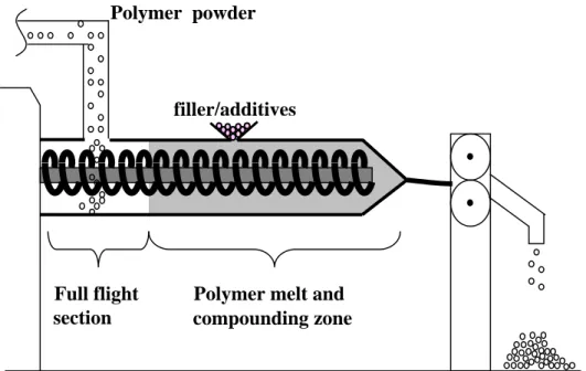
In industrial plant, polymer powder is supplied to feeder in twin-screw extruder, and the fed polymer is heated and compounded inside of the barrel (Fig.1-4). It should be noted that the conventional extruder has several full flight section for the powder transportation. With getting overlooked flight screw section, I have examined the nano-composite formation possessing discrete dispersion of OMLFs via “solid-state processing” (Chapter 4 and 5) [56-58], which leads to successful delamination of OMLFs and broadens the scope of industrial application.
1-4. Structure and Characterization of PLF nano-composites 1-4-1. Structure of PLF nano-composite
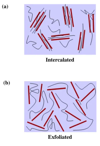
Layered silicates and layered titanate have layer thickness in the order of 1 nm and very high aspect ratio (e.g., 10-1000), thus creating a much higher surface area for polymer/filler intercalation than in conventional composites. Depending on the strength of interfacial interaction between polymer matrix and layered filler (modified or not), two different types of PLF nano-composites are thermodynamically achievable (Figure 1-5) [20].
(1) Intercalated nano-composites: in an intercalated nano-composites, the insertion of polymer matrix into the layered filler structure occurs in a crystallographically regular fashion, regardless of the filler to polymer ratio. Properties of the composites typically resemble those of ceramic materials.
14
Figure 1-4. Illustration of twin-screw extruder. Full flight section is possibly available for solid- state processing.
Polymer melt and Polymer powder
filler/additives
Full flight
section compounding zone
Chapter 1
15
Figure 1-5. Schematic illustration of two different types of thermodynamically achievable polymer/layered filler nano-composites.
(a)
(b)
Intercalated
Exfoliated
16
(2) Exfoliated nano-composites: in exfoliated nano-composites, the individual filler layers are separated in a continuous polymer matrix by an average distance that totally depends on the layered filler loading. Usually, the clay content of an exfoliated nano- composite is much lower than that of an intercalated nano-composite.
1-4-2. Characterization of PLF nano-composites
The structure of the PLF nano-composites has typically been established using wide-angle X-ray diffraction (WAXD) analysis and transmission electron microscope (TEM) observations.
Due to its ease of use and availability, WAXD is most commonly used to probe the PLF nano- composite structure and sometimes to study the kinetics of the polymer melt intercalation. By monitoring the position, shape and intensity of the basal reflections from the distributed filler layers, the nano-composite structure either intercalated or exfoliated may be identified. For example, in the case of exfoliated nano-composites, the extensive layer separation associated with the delamination of the original filler layers in the polymer matrix results in the eventual disappearance of any coherent X-ray diffraction from the distributed filler layers. On the other hand, for intercalated nano-composites, the finite layer expansion associated with the polymer intercalation results in the appearance of a new basal reflection corresponding to the variation of gallery height. Although, WAXD offers a convenient method to determine the interlayer spacing of the filler layers in the original layered fillers and in the intercalated nano-composites (within 1-4nm), however, little can be said about the spatial distribution of the filler layers or any structural inhomogeneities in the PLF nano-composites. Additionally, some layered fillers
Chapter 1
17
initially do not exhibit well-defined basal reflection. Thus, peak broadening and intensity decreases are very difficult to study systematically. Therefore, conclusions concerning the mechanism of nano-composites formation and their structure based solely on WAXD patterns are only tentative.
On the other hand, TEM allows a qualitative understanding of the internal structure, spatial distribution of the various phases, and defect structure through direct visualization. However, special care must be exercised to guarantee a representative cross-section of the sample. The WAXD patterns and corresponding TEM images of two different types of nano-composites are presented in Figure 1-6.
1-5. Matrix polymers
Generally, polymer matrix for nano-composite preparation is determined by specification of the polymer usage. From scientific point of view, polymer matrix represented simple chemical structure has advantage to consider interaction between polymer matrix and nano-filler, polarity of the polymer and so on.
Polypropylene (PP) is one of the most widely used thermoplastic and consists from simple components, carbon and hydrogen. Because of the chemical structure, PP is classified into non- polar polymer. The polarity is the most important factor to achieve nano-filler dispersion.
Therefore, maleic anhydrate grafted polypropylene (PP-g-MA), which has high polarity and compatibility with matrix PP is added to prepare PP-based nano-composite [53, 54]. However, PP-g-MA causes embrittlement for the result nano-composite materials, and the availability for
18
Figure 1-6. (a) WAXD patterns and (b) TEM images of two different types of nano-composite structures.
0 1000 2000 3000
0 200 400 600 800
0 200 400 600 800
0 2 4 6 8 10 12 14 16
Nano-filler
Intercalated
Exfoliated
2Theta /degrees
Intensity /a.u.
(a)
Chapter 1
19 Figure 1-6. (Continued)
(b)
200 nm Exfoliated
200 nm Intercalated
20
the nano-composite is limited. Preparation for non-polar polymer based nano-composite without using compatibilizer is still challenging issue.
Poly(p-phenylene sulfide) (PPS) is a versatile high-performance engineering plastic having prominent heat resistance, chemical resistance, good mechanical properties, and rigidity.
PPSonly consists of a rigid benzene ring and sulfur atom. So, it has possibilities of understanding polymer-filler interaction compared with other polymers. To the best of our knowledge, there are no studies on the preparation of PPS-based nano-composites containing various types of OMLFs.
1-6. Scope of this thesis
The main objective of this study is to bring out the factors that concerned with nano- composite formation and to feed back these factors for the preparation of the polymer nano- composite. For this purpose, I investigated fundamental study of the phase transition of the cationic surfactant located at the interlayer space in montmorillonite, and examined the intercalation behavior of the small molecules by using various types of nano-fillers, which have a strong impact on the explanation for the intercalation kinetics. I chose an optimal OMLF and conducted the PPS-based nano-composites preparation with and/or without shear processing. Furthermore, I have developed more innovative compounding process, i.e., solid- state processing, to delaminate the stacked-and-layered filler in the polymer matrix. And I adopted non-polar polymer as matrix to confirm the processing ability, and to investigate the effect of polarity of the matrix polymer on solid-state processing.
Chapter 1
21
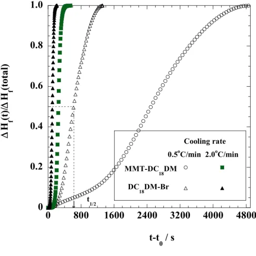
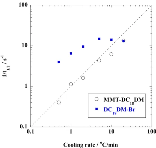
In Chapter 2, I investigated nonisothermal order-disorder transition behavior of alkylammonium ions (Fig. 1-3) in nano-confined space i.e., interlayer space of MMT, compared with crystallized dioctadecyl dimethyl ammonium bromide (DC18DM-Br) through temperature modulated differential scanning calorimeter (TMDSC), WAXD, and FTIR.
In Chapter 3, I investigated the intercalation behavior of small molecules (Fig. 1-3), as a model compound for PPS, into various OMLFs interlayer evaluated from WAXD analysis. In the first part of Chapter 3, the effect of miscibility between small guest molecules and intercalants on the basis of DSC analysis was investigated. After that, the intercalation behavior of the molecules into the various types of OMLFs was discussed. In the remaining part, I chose an optimal OMLF and conducted the PPS-based nano-composites preparation with and without shear processing.
In the first part of Chapter 4, I discussed intercalation behavior with various polymers and OMLFs prepared by melt compound. The results show same trends as small molecules investigated in Chapter 3. In latter part, novel preparation methods, solid-state processing, to improve nano-filler dispersion and to delaminate the stacked-and-layered filler in PPS matrix was conducted. From the results, effectiveness of solid-state processing is clearly showed.
In Chapter 5, I also challenged to prepare non-polar polymer based nano-composite. It is considered that preparation for non-polar polymer-based nano-composite is difficult because polarity of matrix polymer is very important for nano-filler dispersion. Fortunately, I successfully prepared PP/OMLF nano-composite with solid-state processing. In this study, two thresholds during solid-state processing were found for OMLF dispersion.
22
Finally, I summarized the principal results and conclusions derived from this study in Chapter 6.
References
[1] Stewart R, Plastics Engineering, May 2004, 22.
[2] Cox H, Dearlove T, Rodges W, Verbrugge M, “Nanocomposite Systems for Automotive Applications”, in 4th World Congress Nanocomposite 2004, San Francisco, Sep. 1-3, 2004 [3] Okada A, Kawasumi M, Usuki A, Kojima Y, Kurauchi T, Kamigaito O, in D.W. Schaefer, J.E. Mark, Eds., Polymer Based Molecular Composites, Materials Research Society, Pittsburgh, 1990, 171, 45.
[4] Usuki A, Kojima Y, Okada A, Fukushima Y, Kurauchi T, Kamigaito O, J. Mater. Res., 1993, 8, 1174-1178.
[5] Kojima Y, Usuki A, Kawasumi M, Okada A, Kurauchi T, Kamigaito O, J. Polym. Sci. Part A: Polym. Chem., 1993, 31, 983-986.
[6] Kojima Y, Usuki A, Kawasumi M, Okada A, Kurauchi T, Kamigaito O, Kaji K, J. Polym.
Sci. Part B: Polym. Phys., 1994, 32, 625-630.
[7] Kojima Y, Usuki A, Kawasumi M, Okada A, Kurauchi T, Kamigaito O, Kaji K, J. Polym.
Sci. Part B: Polym. Phys., 1995, 33, 1039-1045.
[8] Giannelis EP, Appl. Organomet. Chem., 1998, 12, 675-680.
[9] Gilman JW, Appl. Clay Sci., 1999, 15, 31-49.
[10] Ray SS, Yamada K, Okamoto M, Ueda K, Nano Lett., 2002, 2, 1093-1096
[11] Okamoto M, “Polymer/clay nanocomposites“ in Encyclopedia of Nanoscience and Nanotechnology, H.S.Nalwa, Ed., ASP, California 2004, Vol. 8, pp.791-843.
24
[12] Chen JS, Poliks MD, Ober CK, Zhang Y, Wiesner U, Giannelis EP, Polymer,2002, 43, 4895-4904.
[13] Ray SS, Okamoto K, Okamoto M, Macromolecules, 2003, 36, 2355-2367.
[14] Soma I, Filler Data Book for Practical Use, Kogyo Chosakai Publishing Co., Ltd., 2004.
[15] Hiroi R, Ray SS, Okamoto M, Shiroi T, Macromol. Rapid Commun., 2004, 25, 1359-1364.
[16] Yoshida O, Okamoto M, Macromol. Rapid Commun., 2006, 27, 751-757.
[17] Brindly SW, Brown G, Eds., Crystal Structure of Clay Minerals and Their X-ray Diffraction, Mineralogical Society, London, 1980.
[18] Shen Z, Simon GP, Cheng YB, Polymer, 2002, 43, 4251-4260.
[19] Li Y, Ishii H, ACS Polymeric Materials Science and Engineering Fall Meeting, 2001, 85, 562-563.
[20] Hyun YH, Lim ST, Choi HJ, Jhon MS, Macromolecules, 2001, 34, 8084-8093.
[21] Sukpiron N, Lerner MM, Chem. Mater., 2001, 13, 2179-2185.
[22] Vaia RA, Sauer BB, Tse OK, Giannelis EP, J. Polym. Sci. Polym. Phys., 1997, 35, 59-67.
[23] Aranda P, Ruiz-Hitzky E, Chem. Mater., 1992, 4, 1395-1403.
[24] Gendoya I, Lopez D, Alegria A, Mijangos C, J. Polym. Sci. Polym. Phys., 2001, 39, 1968- 1975.
[25] Greenland DJ, J. Colloid Sci., 1963, 18, 647-664.
[26] Krishnamoorti R, Vaia RA, Giannelis EP, Chem. Mater., 1996, 8, 1728-1734.
[27] Blumstein A, J. Polym. Sci. Part A Polym. Chem., 1965, 3, 2653-2664.
[28] Vaia RA, Teukolsky RK, Giannelis EP, Chem. Mater., 1994, 6, 1017-1022.
Chapter 1
25
[29] Vaia RA, Ishii H, Giannelis EP, Chem. Mater., 1993, 5, 1694-1696.
[30] Weimer MW, Chen H, Giannelis EP, Sogah DY, J. Am. Chem. Soc., 1999, 121, 1615-1616.
[31] Kim TH, Jang LW, Lee DC, Choi HJ, Jhon MS, Macromol. Rapid Commun., 2002, 23, 191-195.
[32] Becker O, Varley R, Simon G, Polymer, 2002, 43, 4365-4373.
[33] Maiti P, Nam PH, Okamoto M, Hasegawa N, Usuki A, Macromolecules, 2002, 35, 2042- 2049.
[34] Kaempfer D, Thomann R, Mulhaupt R, Polymer, 2002, 43, 2909-2916.
[35] Ke YC, Long CF, Qi ZN, J. Appl. Polym. Sci., 1999, 71, 1139-1146.
[36] Messersmith PB, Giannelis EP, J. Polym. Sci. Part A: Polym. Chem., 1995, 33, 1047-1057.
[37] Jimenez G, Ogata N, Kawai H, Ogihara T, J. Appl. Polym. Sci., 1997, 64, 2211-2220.
[38] Yao KJ, Song M, Hourston DJ, Luo DZ, Polymer, 2002, 43, 1017-1020.
[39] Delozier DM, Orwoll RA, Cahoon JF, Johnston NJ, Smith JG, Connell JW, Polymer, 2002, 43, 813-822.
[40] Li CY, Li L, Cai W, Kodjie SL, Tenneti KK, Adv. Mater., 2005, 17, 1198-1202.
[41] Zhang L, Tao T, Li C, Polymer, 2009, 50, 3835-3840.
[42] Du F, Fisher JE, Winey KI, J. Polym. Sci. Polym. Phys., 2003, 41, 3333-3338.
[43] Vladimirov V, Betchev C, Vassiliou A, Papageprgiou G, Bikiaris D, Comp. Sci. Tech., 2006, 66, 2935-2944.
[44] Asuka K, Liu B, Terano M, Nitta K-H, Macromol. Rapid Commun., 2006, 27, 910-913.
[45] Nitta K-H, Asuka K, Liu B, Terano M, Polymer, 2006, 47, 6457-6463.
26
[46] Fu BX, Yang L, Somani RH, Zong SX, Hsiao BS, Phillips S, Blanski R, Ruth P, J.Polym.Sci. Polym. Phys., 2001, 39, 2727-2739.
[47] Fu BX, Gelfer MY, Hsiao BS, Phillips S, Viers B, Blanski R, Ruth P, Polymer, 2003, 44, 1499-1506.
[48] Fina A, Tabuani D, Peijs T, Camino G, Polymer, 2009, 50, 218-226.
[49] Okamoto M, Mater. Sci. Tech., 2006, 22 (7), 756-779.
[50] Vaia RA, Ishii H, Giannelis EP, Chem. Mater., 1993, 5, 1694-1696.
[51] Kawasumi M, Hasegawa N, Kato M, Usuki A, Okada A, Macromolecules, 1997, 30, 6333- 6338.
[52] Kato M, Usuki A, Okada A, J. Appl. Polym. Sci., 1997, 66, 1781-1785.
[53] Yang K, Ozisik R, Polymer, 2006, 47, 2849-2855.
[54] Bellair RJ, Manitiu M, Gulari E, Kannan RM, J. Polym. Sci. Polym. Phys., 2010, 48, 823- 831.
[55] Lee EC, Mielewski DF, Baird RJ, Polym. Eng. Sci., 2004, 44, 1773-1782.
[56] Saito T, Okamoto M, Hiroi R, Yamamoto M, Shiroi T, Macromole. Rapid Commun., 2006, , 27, 1472-1475.
[57] Saito T, Okamoto M, Hiroi R, Yamamoto M, Shiroi T, Polymer, 2007, 48, 4143-4151.
[58] Saito T, Okamoto M, Polymer, 2010, 51, 4238-4242.
Chapter 2
Nonisothermal Order-Disorder Phase Transition of Alkylammonium Ions in Nano-confined Space
27 2-1. Introduction
Over the last few years, the utility of inorganic nanoscale particles as filler to enhance the polymer performance has been established. Of particular interest is recently developed nano-composite technology consisting of a polymer and organically modified layered silicate (organo-clay) because they often exhibit remarkably improved mechanical and various other materials properties when compared to those of virgin polymer or conventional composite (micro/macro-composites) [1-4]. The nano-composites and their self-assembly behavior have recently been approached to produce nano-scale polymeric materials [5]. Additionally, these nano-composites have been proposed as model systems to examine polymer structure and dynamics in confined environments [6-8].
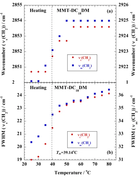
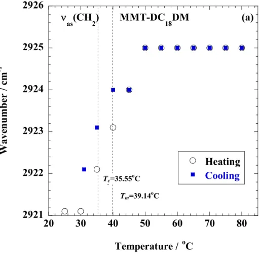
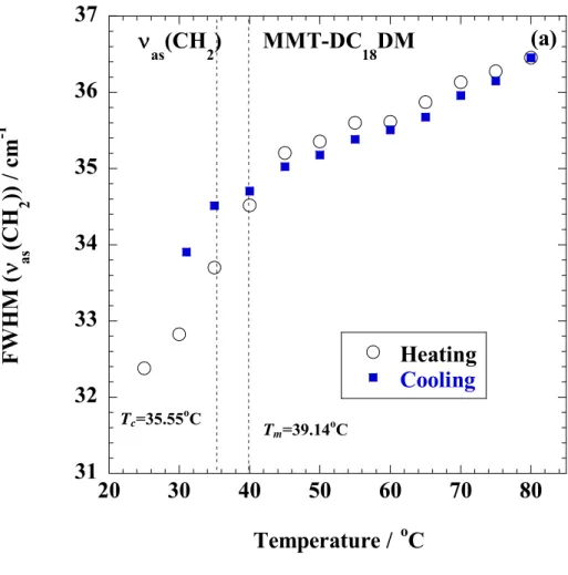
The self-assembly and dynamics of the cationic surfactants intercalated in montmorillonite (MMT) [9-17] have been extensively investigated as well as molecular simulations [17-21]. The conformational disorder in the alkyl chains on MMT surfaces has been reported by Vaia et al. [9] as revealed by Fourier transform infrared (FTIR) spectroscopy. Li and Ishida [13,14] and Osman et al. [12,15] reported that the chain conformational order-disorder transition of the cationic surfactant in MMT galleries. At low temperature (~20 °C) the alkyl chains preferentially are in all-trans conformation. The conformational transition of the chains takes place with increasing temperature, leading to a disordered phase (at 60 °C), where the chains assume a random conformation. The observation of the phase transitions upon heating, variable chain conformation and metastable phases have been extensively investigated. The molecular simulations have helped to understand the molecular-level structure, chain conformation, tilt angle of the alkyl chains and the phase transitions. Heinz et al. [22] reported that about 4 out of 16 torsion angles were gauche in octadecyl trimethylammonium ions on mica
Chapter 2
28
surfaces (C18-mica) at 20 °C, whereas the number of gauche-bonds was increased to 5 at 100°C.
The number of gauche-bonds remains steady with further increasing temperature. Assuming a homogeneous coverage of the entire surface area, the average molecular axis of the octadecyl trimethylammonium ions were inclined relative to the mica surface normal in the angles of 55 ° 2 °. This value well agrees with experimental data [23-25]. The simulation exhibited a major conformational change due to melting of the alkyl chains and an increased mobility of the C18-ions across the surface cavities at elevated temperature. Brovelli et al. [25] discussed that the experimentally observed two distinct phase transition on heating. The first transition at 40 °C was due to breaking of the disordered C18 chains in the island structure [26] and the second transition at 60 °C was due to rearrangements of the C18-ions on the surface. The concept packing density ( AC/AS) (surface saturation), which is given by the average cross-sectional area of an alkyl chain AC in relation to the available surface area AS, and its relation to conformational order were used to understand the behavior of alkyl chains on the surface [17,22]. They reported a simple relation between and the tilt angle for homogeneous layers is given by = cos .
The geometric parameter determines the preferred self-assembly structure into the MMT interlayer spaces. For MMT, AS, is 1.404 nm2 with layer charge of 0.333 [17,27]. The cross section of an all-trans alkyl chains perpendicular to its axis is AC, trans= 0.188 nm2 reported in the literature [17,27]. The value of C18-MMT is low (~ 0.13). At low (< 0.2) the alkyl chains are oriented parrallel to the MMT surface having layer-by-layer structure, which leads to a high degree of conformational disorder and no reversible order-disorder transitions. At intermediate packing density (0.2 < < 0.75), alkyl chains adopt orientations with segmental tilt angles in the range from 78 ° to 42 °. The chain conformations are between liquid-like and crystalline. This simple model is independent of the alkyl chain length, the chemical nature of the surface and of
29 the cationic surfactant head group.
Despite extensive studies, the relation between packing density and chain dynamics under ordering transition is still sparse. Therefore, in this chapter, I aim to confirm the nonisothermal disorder-order phase transition (chain packing) kinetics and disorder transition (chain melting) behaviors including the conformational changes of the chain segment of the alkyl chains in confined space (nano-gallery space of the layered fillers). Knowledge of such investigations shall be useful not only in assessing how does the phase transitions appear to be fundamentally different from those observed in bulk, but also fundamental study for nano-composite formation with organically modified layered filler (OMLF).
Chapter 2
30 2-2. Experimental Section
2-2-1. Materials
OMLF used in this study was montmorillonite (MMT) (cation exchange capacity (CEC) of 90 mequiv/100g, average length of 150-200 nm) intercalated with dioctadecyl dimethylammonium (DC18DM) ions by ion exchange reaction [27], which will be hereafter defined as MMT-DC18DM. The loading amount of the DC18DM cations, which was calculated from thermogravimetric analysis (TGA) was 29.5 wt% [27]. The overall degree of ion exchange was about 89%. The surface charge density is particularly important because it determines the interlayer structure of cationic surfactants as well as CEC. The characterizing method consists of total elemental analysis and the dimension of the unit cell [27]:
Surface charge: e-/nm2 = /ab (2-1)
where is the layer charge (0.33 relative cation density for MMT [28]). a and b are cell parameters of MMT (a=5.18 Å, b=9.00 Å [27]). About 90 % of the interlayer Na+ ions are replaced quantitatively by cationic surfactants [27]. The characteristic parameters of the nano-fillers are also summarized in Table 2-1. From these results, I can estimate the surface area per charge AS, which is calculated to be 1.41 nm2 for MMT. This estimation assumes that the cations are evenly distributed in a cubic array over the nano-filler surface and that half of the cations are located on the one side of the platelet and the other half reside on the other side. As reported by Heinz et al. [17], in the present study, the calculated value of MMT-DC18DM is ~ 0.27, corresponding to the intermediate packing density.
31
Table 2-1. Characteristic parameters of montmorillonite (MMT)
parameters MMT Chemical formula Na0.33(Al1.67Mg0.33) Si4O10(OH)2
Particle size[29] /nm ~100-200
BET area /m2/g ~700
CEC a) /meq/100g ~90(90)
Area per charge/nm2 1.41
Density /g/cm3 2.50
Refractive index (n20D) 1.55
pH 7.5-10
a) Methylene blue adsorption method. The values in the parenthesis are calculated from chemical formula of nano-fillers.
For comparison, dioctadecyl dimethylammonium bromide (DC18DM-Br), purchased from Aldrich, was used as a reference.
2-2-2. Characterization methods
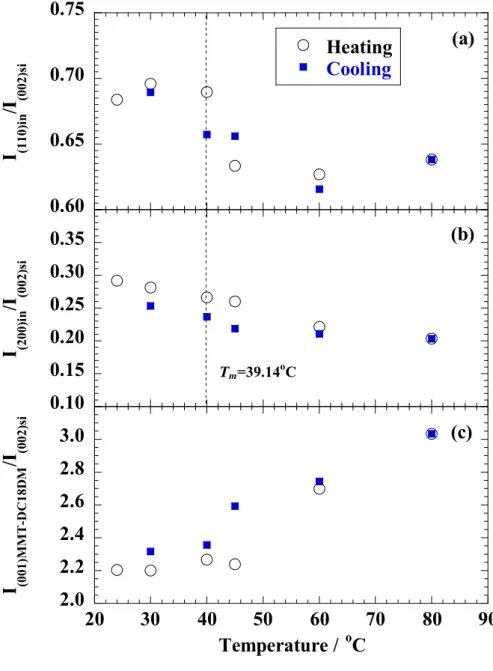
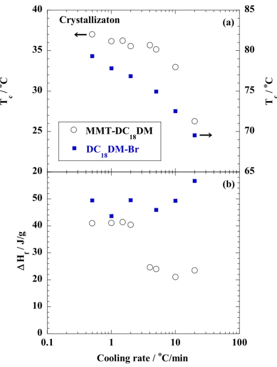
The specimens were characterized by using temperature-modulated differential scanning calorimeter (TMDSC) (TA 2920; TA Instruments) under nitrogen at a heating and cooling rate of 5 C/min with a heating/cooling cycle of the modulation period of 60s for an amplitude of +/-0.769 °C. The chain packing and/or crystallization temperature with cooling from melt (Tc), the melting temperature (Tm) and heat of fusion (H), were calibrated with Indium before experiments.
WAXD analyses were performed using an Mxlabo X-ray diffractometer (MAC Science Co.; 3kW, graphite monochromator, CuK radiation (x=0.154nm), operated at 40kV and 20mA).
Samples were scanned in fixed time mode with counting time of 2 s at room temperature under diffraction angle (2 ) in the range of 1 to 70 .
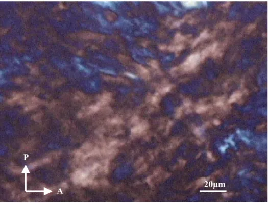
The crystalline texture of DC18DM-Br during cooling process from melt state (~100 C)
Chapter 2
32
was also measured. The thin samples were crystallized on the Linkam hot stage mounted on a polarized optical microscope (POM) (Nikon OPTI-PHOTO2-POL). After the complete crystallization, the samples were observed using POM and fitted with a color-sensitive plate to determine the sign of birefringence, and the photographs were taken. The details regarding POM observation can be found in our previous paper [30].
Fourier transform infrared (FTIR) spectra were collected at 2 cm-1 nominal resolution using a Varian FTS7000 spectrometer equipped with a MCT detector in transmission mode. The spectra were obtained by averaging 32 scans with a mean collection length of 1 s per spectrum.
The background spectra used for reduction were collected at the same temperature (T) range of 25-120 C for DC18DM-Br and 25-80 °C for MMT-DC18DM, respectively, with the samples. The homogenous mixture of KBr powder and DC18DM-Br (fine powder) or MMT- DC18DM.
(powder) in the weight ratio 98:2 were prepared. The mixtures were made into pellets having a thickness of ~ 400 m, were placed in a homemade heating chamber and heated up to a temperature T with a heating/cooling rate of 200-300 C /min. The collected data was processed with Grams/AI® software (Thermo Galactic Co., USA ).