Screw-Assisted
Lingual Orthodontic Treatment
Ryoon-Ki Hong, (Korea)
Ryoon-Ki Hong, DDS, PhD
Chairman, Department of Orthodontics, Chong-A Dental Hospital, Seoul, Korea;
Clinical professor, Department of Orthodontics, College of Dentistry, Seoul National University, Seoul, Korea
Various types of dental implants have recently been tested for their properties as absolute
anchorage points in orthodontic treatment.1-14 Among these types of implants, the micro- or mini-screw
has distinct advantages over other types of implants (such as mini-plates, cylindrical endosseous
implants, or disc-shaped onplants). Its decided advantage as an absolute anchorage device in orthodontic treatment includes its relative ease in selecting proper implant sites; ease of insertion in any desired location; ability to withstand immediate force loading; and minimal irritation of adjacent tissues. Thus in this article, lingual orthodontic methods using screw implants as adjuncts to tooth movement in the various spatial planes will be discussed, along with illustrative clinical cases.
Vertical Tooth Movement
The posterior region of the mid-palatal suture is an appropriate place for placing mini-screw implants because the thickness of soft tissue is minimal, being typically less than 1mm; significant anatomical structures such as nerves and blood vessels are absent; and triangular-shaped cortical bone is abundant.
A skeletal anchorage system known as the Mid-palatal Absolute Anchorage System (MAAS) was developed to withstand more substantial orthodontic forces. This system is versatile enough to allow the provision of orthodontic
forces in any required direction. The usual MAAS design is composed of two mini-screws, each 1.6 mm in diameter, implanted into the posterior region of the mid-palatal suture. A .032_.032•h bracket is bonded to the mini-screw heads, com bined with an integrated .032_.032•h power arm fabricated from either titanium-molybdenum alloy
(TMA) or stainless steel (Fig. 1).
Department of Orthodontics, Chong-A Dental Hospital #648-22, Yoksam Dong, Gangnam Gu
Seoul, 135-911, Korea
Tel: 82-2-2051-2885 Fax: 82-2-569-2812 E-mail: [email protected]
The case shown in Figure 2 outlines a female
patient who had previously undergone orthodontic
treatment without extraction. Her subsequent
chief complaint concerned lip protrusion.
Orthodontic treatment with extraction and
augmentation genioplasty was recommended;
however, the patient wanted non-extraction
orthodontic treatment. The treatment plan was
therefore modified to reflect collective movement
-of the maxillary dentition posteriorly and superiorly with MAAS, and to move the mandibular dentition distally using an MMAW approach
(Multiloop Mushroom Arch Wire).
A modified lingual arch appliance, with hooks on canines and first molars, was bonded from second molar to second molar in the upper arch and the appropriate power arms placed (Fig. 3A). Both the positioning of the hooks and the form of the power arm were determined with the aid of a lateral cephalogram, so that the applied anterior and posterior forces with respect to the centre of resistance of the upper dentition as a whole, would move the upper arch posteriorly and superiorly (Fig. 3B).
After postero-superior movement of the maxillary dentition was effected, MMAW technique was used in the mandible to move the whole dental arch distally (Fig. 4). The patient
was instructed to wear Class ‡V inter-maxillary elastics.
Counter-clockwise autorotation of the mandible following postero-superior movement of the maxillary dentition, and posterior movement of the mandibular dentition, improved the pre-treatment lip protrusion and gummy smile, establishing a more favorable profile (Figs. 5-6 and Table 1).
Sagittal Tooth Movement
During anterior retraction, mini-screw implants combined with lever-arms can perform not only as absolute anchorage points, but are also capable of exerting control over the axial inclinations of the anterior teeth. This method is referred to as the LA-MI(Lever-Arm and Mini-Implant) system.15 The desired line of action of the net retraction force, with respect to the centre of resistance of the anterior segment, is generated by controlling
the length of lever-arm in the anterior area and
the position of the mini-screw head in the
posterior area. Thus, a highly controlled retraction of anterior teeth can be achieved with no loss of anchorage.
The models depicted in Figure 7 indicate the overall reaction that can be expected in an average clinical application. A retraction force parallel to the occlusal plane and applied through the centre of resistance of the anterior teeth will generate
bodily retraction of the anterior segment (Fig.
7Ab). In clinical situations where retraction is to
be performed by simultaneous translation and
intrusion, the retraction force is redirected
through the centre of resistance of anterior teeth as shown in Figure 7Aa. Figure 7Ac demonstrates a configuration that will result in translation and
simultaneous extrusion. Figures 7B and 7C
present the LA-MI system modified for distal crown and root movements of the anterior teeth.
A 25-year-old Korean female presented with a chief complaint of lip protrusion (Fig. 8). The
patient was diagnosed with bi-maxillary
lento-alveolar protrusion, with a missing
mandibular right lateral incisor. The upper and
lower first premolars were selected for extraction.
During the space closure stage, absolute
anchorage for the posterior teeth and bodily
movement of the anterior teeth were required in the maxilla (Fig. 9). Lever-arm length and mini implant positioning were established so that the overall line of action of the retraction force would
pass through the centre of resistance of the 6
anterior teeth, parallel to the occlusal plane (Fig. 10). The pre-existing lip protrusion and crowding were notably improved (Fig. 11). Bodily retrac tion of the anterior teeth was achieved without
anchorage loss, as assessed radiographically (Fig. 12 and Table 2).
Transverse Tooth Movement
In the matter of correction of bilateral posterior crossbites, absolute anchorage is not required because the active and reactive forces involved counterbalance each other during constriction of
expansion of the posterior dentition. However,
during a unilateral posterior crossbite correction, absolute anchorage is necessary to offset reactive forces.
In a unilateral posterior crossbite case, the crossbite is corrected by expanding or constricting the posterior sections of the dentition by using
the MAAS (Midpalatal Absolute Anchorage
System) method with a TMA power arm.
A 21-year-old Korean female presented with
the chief complaint of lip protrusion and anterior openbite (Fig. 13). The upper and lower first premolars were selected for extraction.
After space closure, a posterior scissorsbite of unknown origin in the patient right side occurred
(Fig. 14). To correct the posterior scissorsbite, the hook of the power-arm and the segmental wire in the maxillary right first and second
molar brackets were tied with ligature wire, thus applying lingual movement forces to the molars (Figs. 15 and 16). To provide the flexibility, the power arm was made from TMA.
The preexisting lip protrusion and anterior
openbite were corrected, following desirable
retraction of the upper and lower anterior teeth (Figs. 17-18 and Table 3).
Legends to Figures
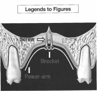
Figure 1. The Mid-Palatal Absolute Anchorage System (MAAS).
Two mini-screws of 1.6mm diameter and 6mm length have been implanted in the mid-palatal suture region between the maxillary left and right first molars. A .032_.032•h bracket has been bonded onto the mini-screw heads, and a. 032_.032•h stainless steel (or TMA) power-arm with customized
form has been engaged. With this system, a considerable amount of orthodontic force can be applied and it is possible to direct forces in any desired direction. Various forms of power-arm
Figure 2. Pre-treatment facial and intra-oral photographs.
A convex profile and Angle Class ‡U relationship are noted. Lip fullness and gummy smile are observed.
Fig. 3A Fig. 3B
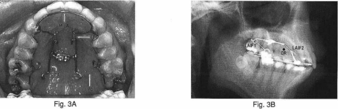
Figure 3. MAAS for postero-superior movement of the maxillary dentition.
A. Occlusal view: Orthodontic force was applied postero-superiorly to the maxillary arch by attaching power chains from the power-arm to spurs on a modified lingual arch. Note the modified lingual arch (M-LA); power-arm (PA); and power chain (PC).
B. Cephalometric radiograph taken after MAAS placed in situ. The position of the hook on the modified lingual arch and the ideal matching form of the power-arm were determined on the initial lateral cephalogram so that the applied forces anteriorly and posteriorly, with respect to the centre of resistance of the upper dentition, would move the whole upper arch posteriorly and superiorly. Note CR, the collective centre of resistance of the maxillary dentition; LAF1, the line of
action of postero-superior orthodontic force distal to the maxillary arch centre of resistance ; LAF2, the line of action of postero-superior orthodontic force in anterior area of the maxillary dental arch.
Figure 4. After postero-superior movement of the maxillary dentition, an MMAW was placed in the mandible, and Class ‡V
inter-maxillary elastics were used to move mandibular dentition distally.
Figure 5. Post-treatment facial and intra-oral photographs. Improvements to the convex facial profile and gummy smile are observed. The Angle Class ‡U molar relationship was corrected.
Figure 6. Superimpositions of cephalometric
tracings before (black) and after (red)
treatment. Counter-clockwise autorotation
of the mandible following postero-superior movement of the maxillary dentition, and
posterior movement of the mandibular dentition occurred.
Figure 7. Analysis of the reactions of anterior teeth to differing applications of linear retraction forces in the LA-MI system.
In all cases, an .018 _.018•h stainless steel mushroom archwire is placed from first molar to first molar in the upper arch, and 0.9mm stainless steel lever-arms are soldered onto the mushroom archwire between the lateral incisors and canines. The desired line of action for retraction force with respect to the centre of resistance
of the anterior segment is established by adjusting the length of the lever-arm and the position of the mini-implant. The tendency toward translation or tipping, and simultaneous extrusion or intrusion of the anterior teeth during retraction will be determined by the direction of the retraction force. Note LA, lever-arm; MI, mini implant; and CR, centre of resistance of the anterior teeth.
A. Force system for bodily movement of the anterior teeth: a. The anterior teeth will be retracted bodily and intruded. b. The anterior teeth will be retracted bodily.
c. The anterior teeth will be retracted bodily and extruded. B. Force system for distal crown movement of the anterior teeth:
a. The crowns of the anterior teeth will move distally and intrusively. b. The crowns of the anterior teeth will move distally.
c. The crowns of the anterior teeth will move distally and be extruded. C. Force system for distal root movement of the anterior teeth:
a. The roots of the anterior teeth will move distally and be intruded. b. The roots of the anterior teeth will be moved distally.
Figure 8. Pre-treatment facial and intra-oral photographs. This patient exhibited a convex profile and crowding. Due to a missing mandibular right lateral incisor, the maxillary midline coincided with the centre of the mandibular left central incisor, and the molars were in super Class ‡T relationships. The overjet and overbite were 5.0mm and 1.0mm, respectively.
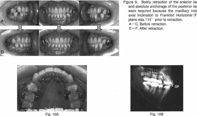
Figure 9. Bodily retraction of the anterior teeth and absolute anchorage of the posterior teeth were required because the maxillary incisor axial inclination to Frankfort Horiztonal (FH) plane was 114•‹ prior to retraction.
A-C. Before retraction. D-F. After retraction.
Fig. 10A Fig. 10B
Figure 10. The LA-MI system for bodily retraction of the anterior teeth.
A. Occlusal view: Cylindrical mini-screws 2mm in diameter and 13mm in length were implanted on the lateral side of the posterior palate in a flapless surgical and drill-free manner.
B. Lateral cephalogram: The position of the mini-implant and the hooks were determined on the lateral cephalogram so
that the line of action of retraction force (LARF) would pass through the centre of resistance of the 6 anterior teeth (CR) and would be parallel to the occlusal plane (OP). Note CR, the centre of resistance of the 6 anterior teeth; LARF, the line of action of the retraction force; OP, the occlusal plane.
Figure 11. Post-treatment facial and intra-oral photographs. Lip protrusion was improved and favorable interdigitation with a super Class ‡T molar relationship was achieved.
Figure 12. Superimpositions of cephalometric tracings before treatment (black), before retraction (blue), and after treat ment (red).
A. Overall superimposition: No downward and backward
rotation of the mandible is evident. Alteration of nasal morphology by augmentation rhinoplasty is observed. Lip protrusion was improved.
B. Regional superimposition: The upper incisors were
retracted bodily and intrusively, and the upper molars did
not move mesially at all during retraction. The lower
incisors were bodily retracted and the lower molars moved mesially to a slight degree.
Figure 13. Pre-treatment facial and intra-oral photographs. The patient showed lip protrusion and anterior open bite with crowding.
-Figure 14. After space closure, a posterior scissorsbite of unknown origin in the patient
right side occurred. A-C. Before retraction. D-F. After retraction.
Figure 15. Before (A) and after (B) correction of the right unilateral posterior crossbite.
Fig. 16A Fig. 16B
Figure 16. Correction of unilateral posterior crossbite by transverse constriction with MAAS. A. Before power-arm activation. Note PA-TMA, power-arm made from TMA.
B. After power-arm activation. The hook of the power-arm and the segmental wire in the maxillary right first and second molar brackets were tied with ligature wire, thus applying lingual movement forces to the molars. Note
PA-TMA, power-arm made from TMA; SS-LW, stainless steel ligature wire.
-Figure 17. Post-treatment facial and intra-oral photographs of patient. Lip protrusion and anterior open bite were improved and favorable interdigitation was achieved.
Figure 18. Superimpositions of cephalometric tracings before
(black) and after (red) treatment. Desirable retraction of
the upper and lower incisors occurred and the upper and lower molars moved mesially to a slight degree.
Table 2. Cephalometric summary.
Table 1. Cephalometric summary.
Table 3. Cephalometric summary.
-REFERENCES
1. Creekmore TD, Eklund MK. The possibility of skeletal anchorage. J Clin Orthod. 1983; 17: 266-269.
2. Kanomi R. Mini-implant for orthodontic
anchorage. J Clin Orthod. 1997; 31: 763-767. 3. Lee JS, Park HS, Kyung HM. Micro-implant anchorage for lingual treatment of a skeletal Class II malocclusion. J Clin Orthod. 2001; 35: 643-647.
4. Karaman AI, Basciftci FA, Polat O. Unilateral
distal molar movement with an implant
supported distal jet appliance. Angle Orthod. 2002; 72: 167-174.
5. Kyung SH, Hong SG, Park YC. Distalization of maxillary molars with a midpalatal miniscrew. J Clin Orthod. 2003; 37: 22-26.
6. Park YC, Lee SY, Kim DH, Jee SH. Intrusion of posterior teeth using mini-screw implants. Am J Orthod Dentofacial Orthop. 2003; 123: 690-694.
7. Umemori M, Sugawara J, Mitani H, Nagasaka H, Kawamura H. Skeletal anchorage system
for open-bite correction. Am J Orthod
Dentofacial Orthop. 1999; 115: 166-174. 8. Chung KR, Kim YS, Lee Linton J, Lee YJ. The
miniplate with tube for skeletal anchorage. J Clin Orthod. 2002; 36: 407-412.
9. Roberts WE, Smith RK, Zilberman Y, Mozsary PG, Smith RS. Osseous adaptation to continu ous loading of rigid endosseous implants. Am J Orthod. 1984; 86: 95-111.
10. Roberts WE, Helm FR, Marshall KJ, Gongloff RK. Rigid endosseous implants for orthodontic
and orthopedic anchorage. Angle Orthod.1989; 59: 247-255.
11. E man J, Lekholm U, Jemt T, Thilander B. Osseointegrated implants as orthodontic anchorage in treatment of partially edentulous adult patients. Eur J Orthod. 1994; 16: 187-201.
12. Wehrbein H, Feifel H, Diedrich P. Palatal implant anchorage reinforcement of posterior teeth: A prospective study. Am J Orthod Dentofacial Orthop. 1999; 116: 678-686. 13. Block MS, Hoffman DR. A new device for
absolute anchorage for orthodontics. Am J Orthod Dentofacial Orthop. 1995; 107: 251-258.
14. Costa A, Raffaini M, Melsen B. Miniscrew as orthodontic anchorage: A preliminary report. Int J Adult Orthod Orthognath Surg 1998; 13
: 201-209.
15. Hong RK, Heo JM, Ha YK. Lever-arm and mini-implant system for anterior torque control during retraction in lingual orthodontic treatment. Angle Orthod 2004; 75: 129-141.