Japan Advanced Institute of Science and Technology
JAIST Repository
https://dspace.jaist.ac.jp/Title
Modulation Doping for Repetition Coded BICM-ID
with Irregular Degree Allocation
Author(s)
Zhao, Dan; Dauch, Axel; Matsumoto, Tad
Citation
Proceedings 2009 International ITG Workshop on
Smart Antennas (WSA 2009): 312-318
Issue Date
2009-02
Type
Conference Paper
Text version
publisher
URL
http://hdl.handle.net/10119/9114
Rights
Copyright (C) 2009 EURASIP. Dan Zhao, Axel Dauch,
Tad Matsumoto, Proceedings 2009 International ITG
Workshop on Smart Antennas (WSA 2009), 2009,
312-318.
Description
International ITG Workshop on Smart Antennas
-WSA 2009, February 16-18 2009, Berlin, Germany
Modulation Doping for Repetition Coded BICM-ID with Irregular
Degree Allocation
Dan Zhao
Japan Advanced Institute of Science and Technology, Japan Email: [email protected]
Axel Dauch
Information Technology University of Ulm, Germany Email: [email protected]
Tad Matsumoto
Japan Advanced Institute of Science and Technology, Japan
Email: [email protected] and
Center for Wireless Communication at University of Oulu, Finland Email: [email protected] Abstract—A new BICM-ID technique that makes efficient use of a
mixture of standard Gray and anti-Gray extended mapping, combined with irregular degree-allocated repetition code with check nodes. It is shown that with the proposed technique, very low rate codes that can achieve turbo cliff at a very low Es/N0 value
range can well be designed, and that the EXIT chart analysis and chain simulation results are exactly consistent with each other.
Index terms - extended mapping; repetition code; irregular node allocation; EXIT analysis; turbo cliff; capacity;
I. INTRODUCTION
In Bit-Interleaved Coded Modulation with Iterative Detection/Decoding (BICM-ID) [1], transmitter is comprised of a concatenation of encoder and bit-to-symbol mapper separated by a bit interleaver, and at the receiver, iterative processing is invoked, according to the standard turbo principle.
Performances of BICM-ID have to be evaluated by the convergence and asymptotic properties [2], which are represented by the threshold signal-to-noise power ratio (SNR) and bit error rate (BER) floor, respectively. In principle, since BICM-ID is a serially concatenated system, analyzing its performances can rely on the area property [3] of the extrinsic information transfer (EXIT) chart. Therefore, the transmission link design based on BICM-ID falls into the issue of matching between the demapper and decoder EXIT curves.Various efforts have been made in the seek of better matching between the two curves for minimizing the gap while still keeping the tunnel open, aiming, without requiring heavy detection/decoding complexity, at achieving lower threshold SNR and BER floor. Reference [4] introduces a technique that makes good matching between the detector and decoder EXIT curves using low density parity check (LDPC) code in multiple input multiple output (MIMO) spatial multiplexing systems.
It has been believed that a combination of Gray mapping and Turbo or LDPC codes achieves the best performance comparing with other combinations for BICM-ID. However, Ref. [5] proposes another approach towards achieving good matching between the two curves by introducing different mapping rules, such as anti-Gray mapping, which allows the use of even simpler codes, such as convolutional codes, and with which still it is possible to achieve BER pinch-off (corresponding to the threshold SNR). Another good idea
that can provide us with design flexibility is extended mapping (EM) presented by [6], [7], [8] where with 2m -QAM, more than m bits, lmap, are allocated to one signal
point in the constellation. With this mapping rule, the left-most (LM) point of the demapper EXIT function has a lower value than with the Gray mapping, but the right-most (RM) point becomes higher. With this setting, the demapper EXIT function achieves better matching with even weaker codes such as small memory length convolution codes, and of the most practical importance is the fact that hardware complexity of the modulator and demodulator remains the same as that with the original 2m- QAM.
In Ref [9], we proposed techniques that combine EM with an extremely simple code, repetition code, concatenated with single parity check code with irregular degree allocation. Even with this very simple combination, the EXIT curves of the demapper and decoder match well, and we can achieve BER pinch-off exactly at a designed SNR. The complexity for the Ref [9]’s proposed technique is extremely low, because EM does not require higher order modulation format and no iterations are needed in the decoder itself. Even with such simple structure, near-capacity performance can be achieved [9].
However, this technique is not suitable in designing BICM-ID with low rate codes that achieve BER pinch-off at very low SNR. This is because the LM point of the demapper EXIT function, corresponding to decoder feedback mutual information MI=0, is already very low, and there is not enough room to further lowerthe EXIT LM point while avoiding the intersection between the demapper and decoder curves. To solve this problem, this paper introduces modulation doping technique which mixes the labeling rules (=bit patterns allocated to each constellation point) for the extended anti-Gray mapping and the standard Gray mapping, at a certain ratio. Since the demapper EXIT function with Gray mapping is relatively flat, its LM point has the higher MI value than EM mapping rules. Therefore, with modulation doping the demapper EXIT LM point is lifted up from that without doping, and the amount depends on the doping ratio.
With the modulation doping technique combined with repetition coded EM BICM-ID with irregular degree allocation, we can achieve more degrees-of-freedom in choosing the parameter values so that we can achieve better matching between the demapper and decoder EXIT curves.
This work was supported by the Japanese government funding program, Grant-in-Aid for Scientific Research (B), No. 20360168..
The paper is organized as follows. The system model is described in Section II. The basic structures of the technique presented by [9] are summarized in Section II; The structures introduced in [9] has three forms; (A) is comprised of only EM and repetition code, (B) comprised of variable and check nodes with regular degree allocation, and (C) comprised of EM BICM-ID with irregular degree allocation. The notations, (A), (B), and (C), are commonly used to describe Sub-section Indexes in this paper to identify the structures. Their convergence performances are evaluated in Section III using EXIT chart, and chain simulation results are shown in Section IV. Section V further extends the structures described in Section III to the case where modulation doing is combined. Results of the EXIT analysis and BER simulations are presented to verify the advantageous points of the combined use of EM and modulation doping. It is shown that the EXIT analysis and BER results are exactly consistent each other even with such low rate code cases where BER threshold happens at very low SNR range. Finally Section VI concludes this paper.
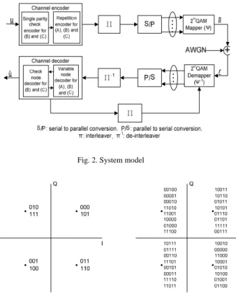
Fig. 2. System model
Fig. 1. Extended mapping 4-QAM lmap=3 and lmap=5, optimized with a priori
information
II. SYSTEM MODEL WITHOUT DOPING
A schematic diagram of the BICM-ID system is shown in Fig. 1.
Transmitter
The binary bit information sequence u to be transmitted is encoded by (A) a simple repetition code, (B) a single parity check code where a single parity bit is added to every
dc-1 information bits, followed by a repetition code. dc is
referred to as check node degree. The structure (C) is the same as (B), but the repetition times dv, referred to as
variable node degree, take different values in one whole block (transmission frame); if dv takes several different
values in a block, such code is referred to as having irregular degree allocation. It is assumed that throughout the paper dc
takes only one identical value as in [4].
The coded bit sequence, encoded by the encoder (A), (B), or (C), is first bit-interleaved, segmented into lmap–bit
segments, and then the each segment is mapped on to one of the 2m constellation points for modulation. Since lmap>m with
the EM technique, more than one labels having different bit patterns in the segment are mapped on to each constellation point. However, there are many possible combinations of bit patterns to be allocated to the constellation points. This paper uses the labels assigned to the each constellation point, obtained by [7], so that, with full a priori information, the mutual information (MI) between the coded bit and the demapper output extrinsic LLR at the right most point of the demapper EXIT curve is maximized. Fig. 2 shows the optimal labeling for 4-QAM with lmap=3 and 5. The
complex-valued signal modulated according to the mapping rule, referred to as Ψ, is finally transmitted to the wireless channel.
Channel
This paper assumes frequency flat block fading additive white Gaussian noise (AWGN) channel. If the channel exhibits frequency selectivity due to the multipath propagation, the receiver needs an equalizer to eliminate the
inter-symbol interference. However, combining the technique presented in this paper with the turbo equalization framework [10]-[13] is rather straightforward.
It is assumed that transmission chain is properly normalized so that the received symbol energy-to-noise power spectral density ratio Es/N0= 1/ ; with this
normalization, we can properly delete the channel complex gain term from the mathematical expression of the channel. The discrete time description of the received signal y(k) is then expressed by
2
n σ
y(k)=x(k)+n(k), (1)
where, with k being the symbol timing index, x(k) is the transmitted modulated signal with unit power, and n(k) the zero mean complex AWGN component with variance (i.e., <|x(k)| 2 n σ 2 >=1, <n(k)>=0, and <|n(k)|2>= 2). n σ Receiver
At the receiver side, the iterative processing is invoked, where extrinsic information is exchanged between the demapper and decoder. The extrinsic LLRs calculated by soft input soft output (SISO) decoding/demapping are fed back and used for demapping/decoding as a priori LLR; the iteration continues until no more relevant gains in extrinsic MI can be achieved [14]; when such convergence point is reached, binary decisions are made on the information bits based on the a posteriori LLR at the variable node. Therefore,
the larger the MI at the convergence point, the lower the BER floor, which is depending on the matching between the encoder and the mapping rule.
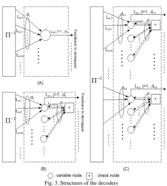
Fig. 3. Structures of the decoders
The demapper calculates from the received signal point
y(k), corrupted by AWGN, the extrinsic LLR of the µth bit in the symbol transmitted at the kth symbol timing, by
. ))) ( ( ) ( exp( | | exp ))) ( ( ) ( exp( | | exp ln )] ( [ 1 0 , 1 2 2 , 1 2 2
∑
∏
∑
∏
∈ = ≠ ∈ = ≠ − ⎭ ⎬ ⎫ ⎩ ⎨ ⎧− − − ⎭ ⎬ ⎫ ⎩ ⎨ ⎧ − − = S s l v v v a v N S s l v v v a v N e map map s b L s b s y s b L s b s y k b L μ μ μ σ σ where s denotes a signal point in the constellation, S(2)
0(S1)
indicates the set of the labels having the µth bit being 0(1), and La(bv(s)) the a priori LLR fed back from the decoder
corresponding to the vth position in the label allocated to the signal point s.
A. Repetition Coded EM BICM-ID
Fig. 3 (A) shows a block diagram of the decoder with the structure (A). The dv bits constituting one segment, output
from the de-interleaver, are connected to one variable node, where the a priori LLR to be updated is calculated by summing up the (dv-1) LLRs, as
∑
≠ = = dv j i i i a j e L L , 1 , , , (3)to produce the extrinsic LLR for the jth bit in the segment. This process is performed for all the other bits in the same segment as well as for all the other segments independently in the frame. Finally, the updated extrinsic LLRs are interleaved, and fed back to the demapper. With the a priori LLRs provided in the form of the decoder’s output extrinsic LLR, demapper again performs the processing of Eq. (2) to update the demapper output extrinsic LLRs. This process is repeated. Obviously, the rate of this code is 1/dv, and the spectrum efficiency is lmap/dv bits per symbol.
B. Repetition Coded EM BICM-ID with Check Nodes
Fig. 3 (B) shows a block diagram of the decoder with the structure (B). The dv bits constituting one segment, output
from the de-interleaver, are connected to a variable node, and
dc variable nodes are further segmented and connected to a
check node decoder; those demapper output bits in one segment, connected to the same variable node decoder, are not overlapping with other segments, and so is the case of the variable node segmentation. Therefore, no iterations in the decoder are required. The extrinsic LLR update for a bit at the check node is exactly the same as the check node operation in the LDPC codes, as
□+ La,cnd,i
∑
≠ = = c d k i i k cnd e L , 1 , , , (4)where ∑□+ indicates the box-sum operator [15].
The extrinsic LLR, calculated by the check node decoder, is fed back to its connected variable node decoder, where it is further combined with (dv-1) apriori LLRs forwarded from
the demapper via the de-interleaver, as
∑
≠ = + = dv j i i i a k cnd e j e L L L , 1 , , , , . (5)This process is performed for the other bits in the same segment, and also for all the other segments independently in the same transmission block. Finally, the updated extrinsic LLRs obtained at the each variable node are interleaved, and fed back to the demapper. With the a priori LLRs provided in the form of decoder’s output extrinsic LLR, demapper again performs the processing of (2) to update the demapper output extrinsic LLRs. This process is repeated. The rate of this code is(dc−1)/(dc⋅dv), and the spectrum efficiency is
) /( ) 1 ( c c v map d d d
l ⋅ − ⋅ bits per symbol.
C. Irregular Degree Allocations
Fig. 3 (C) shows a block diagram of the decoder with the structure (C). The segment-wise structure of (C) is exactly the same as that of (B), but the variable node degrees dv,i may
have different values segment-by-segment. The equations for the LLR update are also the same as that for (B), but the calculations have to reflect different values dv,i of the variable
node degrees. The rate of the code is (dc-1)/(dc·∑ai·dv,i), and
the spectrum efficiency is lmap·(dc-1)/(dc·∑ai·dv,i) bits per
symbol, where ai represents the ratio of variable nodes
having degree dv,i in a block.
III. DESIGN BASED ON EXIT CHART
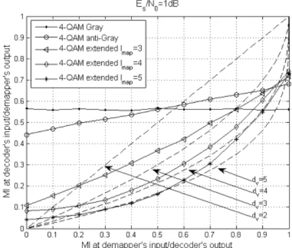
Fig. 4 shows EXIT curves for 4-QAM demappers with
lmap as a parameter, where the labels were determined so that
with Gray mapping is presented in the figure. It is found that the Gray mapping has a completely flat EXIT curve, while anti-Gray mapping has a decay. With lmap=m, since mapping
rule does not change the constellation constraint capacity (CCC), the area under the EXIT curves has to stay almost the same so far as the same modulation is used (m=constant). With EM, the left most point is further decreased, and the right most point increased. However, the area under the curve is smaller than without EM, because even with lmap>m,
still the spectrum efficiency of the modulation itself stays the same (=m).
Fig. 4. EXIT chart: 4-QAM extended mapping lmap=2,…,5 combined
with repetition code dv=2,…,5
(A) Repetition Code
With the Gaussian assumption for the LLR distribution, the EXIT function of the repetition code is given by
(
)
( )
⎟⎠⎞ ⎜ ⎝ ⎛ − ⋅ = − 2 , 1 ,v v 1 av e J d J I I . (6)where Ia,v is the variable node input a priori MI and Ie,v is its
output extrinsic MI. J() and J-1() are the functions that convert the square-root variance σ of LLR to its corresponding MI, and its inverse, respectively [2]. Obviously, (6) is corresponding to (3) for LLR update, with which Ia,v= Ie,dem with Ie, dem being the demapper output
extrinsic MI.
Fig. 5. EXIT chart: 4-QAM EM lmap=5 combined with 3 kinds of repetition code due to structures (A), (B) and (C)
(B) Repetition Code with Check Node
The check node EXIT function can be approximated by [16]
(
)
(
c acnd)
cnd e J d J I I , 1 , =1− −1⋅ 1− − , (7) where(
)
⎟⎠⎞ ⎜ ⎝ ⎛ ⋅ = − 2 , 1 ,cnd v adec a J d J I I . (8)The EXIT function of the whole decoder comprised of the variable and check node decoders can be calculated by combining Eq. (6) and (7) [4], as
(
)
(
)
(
)
⎟⎠⎞ ⎜ ⎝ ⎛ − ⋅ + = − − 2 , 1 2 , 1 ,dec v 1 adec ecnd e J d J I J I I , (9)with Ia,dec= Ie,dem.
(C) Irregular Repetition Code with Check Node
The EXIT function of the whole decoder with the structure (C) can be obtained by weighting the segment-wise EXIT functions given by (9), by ai corresponding to their
distributions, as
(
) (
)
(
)
∑
∑
⋅ ⎟ ⎠ ⎞ ⎜ ⎝ ⎛ − ⋅ + ⋅ ⋅ = − − i i v i i cnd e dec a i v i v i dec e d a I J I J d J d a I , 2 , 1 2 , 1 , , , 1 . (10) Hence, the shape of the combined code EXIT function can be flexibly controlled so that better matching between demapper and decoder curves can be achieved.Fig. 5 shows EXIT functions of the decoders (A), (B), and (C) for the degree allocations presented in the box in the
figure, where the code rates are 1, 0.99, and 1.29, respectively. It is found by comparing Figs. 4 and 5 that the EXIT functions of EM and the repetition code with check nodes can be well matched by changing the degree allocations ai, by which we can expect sharp turbo cliff to
happen at their corresponding threshold Es/N0, even though
the structures of (A), (B), and (C) are very simple and easy to implement.
IV. NUMERICAL RESULTS
A series of simulations was conducted with enough number of bits transmitted to verify the advantageous characteristics of the techniques proposed. As described above, the EM technique does not change the CCC, and therefore the capability of achieving near capacity performance even with the very simple structure, which is the most significant advantage of the proposed technique, is mostly in a low Es/N0 value range (or equivalently low rate
code case). If the CCC is much lower than the Gaussian capacity at the system’s operation Es/N0 point, no significant
merit can be expected, and obviously larger modulation format should be used in such case.
Fig. 7. BER curves optimized by irregular repetition code Fig. 6. EXIT chart: 4-QAM EM lmap=5 combined with repetition code dv=5
With irregular degree allocation of (C), as shown by Fig. 6, the trajectory sneaks through the narrowly tiny open tunnel, and finally reaches the intersection point. With the structure (A), the adjustable parameters are only lmap and dv.
We therefore have introduced the check node in (B), and furthermore, irregular degree allocation in (C), both to (A). Two BER curves with lmap=5 EM 4-QAM with structure (C)
are shown in Fig. 7, together with lmap=5 EM 4-QAM and
dv=5 to demonstrate the design flexibility. The degree
allocations are shown under the figure caption. In fact, the allocation parameters for the rate 1.29 code, of which BER is indicated by “o” in the figure, are exactly the same as that shown in Fig. 5 for (C) with Es/N0=3.1dB. It is found that the
EXIT and BER curves, presented in Figs. 5 and 8, are exactly consistent with each other (at Es/N0=3.1dB, EXIT
tunnel opens and BER turbo cliff happens). These observations indicate that with the design flexibility made available by introducing the irregular structure, we can flexibly control the threshold Es/N0 and the error floor.
Standard (non extended) Mapping (1-d)×100% Extended Mapping d×100% coded bit 1 Π symbol E1 To Channel coded bit 2 coded bit 3 coded bit i coded bit N Serial -to-Parallel Conversion symbol E2 symbol En symbol S2 symbol S1 symbol Sm Mapper
Fig. 8. Block Diagram of Modulation Doping
V. MODULATION DOPING
The technique described above is flexible in making good matching between the demapper and decoder EXIT curves, but is not suitable in designing BICM-ID with very low rate codes that achieve the BER pinch-off at very low SNR. This is because the LM point of the demapper EXIT function, corresponding to decoder feedback mutual information MI=0, is already very low, and there is not enough room to further lower the EXIT LM point while avoiding the intersection between the demapper and decoder curves. To solve this problem, this paper applies the idea of mixing modulation symbols having different labeling rules for the extended anti-Gray mapping and the standard Gray mapping, at a certain ratio. Since the demapper EXIT function with Gray mapping is relatively flat, its LM point has the higher MI value than EM mapping rules. Therefore, with modulation doping the demapper EXIT LM point is lifted up from that without doping, and the amount depends on the doping ratio.
With EM, more than one labels having different bit patterns in the segment are mapped on to each constellation point (lmap>m), while without mapping extension, such as
standard Gray mapping, only one bit pattern in the segment is mapped on to each constellation point (lmap=m). Fig. 8
shows a block diagram of the modulation doping system. The spectrum efficiency of the system then becomes
{
d •m+ −d •lmap}
Rc= (1 )
η , where d and (1-d) are the ratios of the symbols with doped (standard) mapping and extended mappings, respectively, in a transmission frame. Rc
is the code rate, given by Rc=(dc-1)/(dc·∑ai·dv,i), where ai is
the ratio of the variable node having degree dv,i. It has been
assumed that the interleaver is long and random enough so that the repetition encoder output bits are uniformly spread over the whole transmission frame.
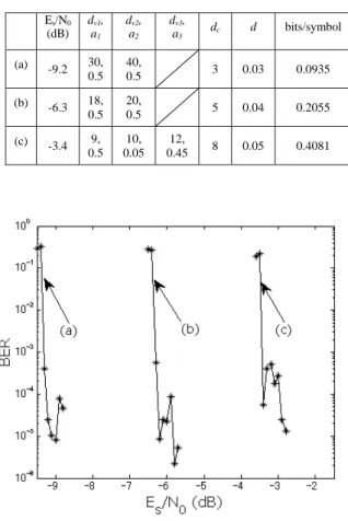
Fig. 9 shows EXIT curves of some representative design examples using EM 4QAM with lmap=5: Their corresponding
Table 1. Degree allocations of the codes shown in Fig. 9 Es/N0 (dB) dv1, a1 dv2, a2 dv3, a3 dc d bits/symbol (a) -9.2 30, 0.5 40, 0.5 3 0.03 0.0935 (b) -6.3 18, 0.5 20, 0.5 5 0.04 0.2055 (c) -3.4 9, 0.5 10, 0.05 12, 0.45 8 0.05 0.4081
Fig. 9. EXIT chart: Low rate design case
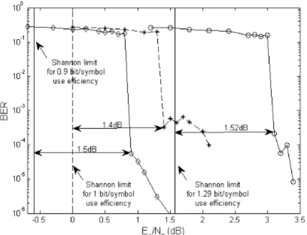
Fig. 10. BER Performance for the code design of Table 1
code design parameters and their threshold Es/N0 values are
summarized in Table 1. A series of chain simulations for the code designs shown in Table 1 has been conducted to verify the advantageous characteristics of the techniques proposed
in this paper. The results of the chain simulations conducted to obtain the trajectories for the code parameters shown in Table 1are also shown in Fig. 9. It should be emphasized that the trajectory and EXIT curve are exactly consistent each other. Fig. 10 shows the BER performance for the code design of Table 1. It is found that the BER pinch-off happens exactly at the values indicated by the EXIT chart analysis.
VI. CONCLUSIONS
In this paper, a new BICM-ID technique that makes efficient use of a mixture of standard Gray and anti-Gray extended mapping, combined with irregular degree-allocated repetition code with check nodes has been proposed. Mathematical details as well as EXIT analysis and BER simulations results have been provided,. It has been shown that with the proposed technique, very low rate code that can achieve a turbo cliff at a very low Es/N0 value range can well
be designed, and that the EXIT chart analysis and chain simulation results are exactly consistent with each other.
REFERENCES
[1] G.Caire, G.Taricco and E.Biglieri, "Bit-Interleaved Coded Modulation", IEEE Trans. on Inform. Theory, vol.44, no.3, pp. 927-946, May 1998.
[2] J. Hagenauer, "The EXIT Chart - introduction to extrinsic information transfer in iterative processing", 12th European Signal Processing Conference (EUSIPCO), pp. 1541–1548, 2004.
[3] S. ten Brink, "Convergence Behavior of Iteratively Decoded Parallel Concatenated Codes", IEEE Trans. on Comm., vol.49, pp. 1727–1737, Oct. 2001.
[4] S.ten Brink, G.Kramer, A.Ashikmin, "Design of low-density parity-check codes for modulation and detection", IEEE Trans. on Comm., vol.52, pp. 670-678, June 2004.
[5] F. Schreckenbach, N. Görtz, J. Hagenauer, G. Bauch. "Optimized Symbol Mappings for Bit-Interleaved Coded Modulation with iterative decoding", IEEE GLOBECOM’03, vol.6, pp. 3316-3320, Dec. 2003
[6] T. Clevorn and P. Vary, "Iterative Decoding of BICM with Non-Regular Signal Constellation Sets", International ITG Conference on Source and Channel Coding, 2004.
[7] P. Henkel, "Extended Mappings for Bit-Interleaved Coded Modulation", IEEE PIMRC, pp. 1-4, 2006.
[8] P. Henkel, "Doping of Extended Mapping for Signal Shaping" In Vehicular Technology Conference, 2007. VTC2007-Spring, IEEE 65th
.
[9] D. Zhao, A. Dauch, and T. Matsumoto, “BICM-ID Using Extended Mapping and Repetition Code with Irregular Node Degree Allocation”, Accepted for presentation in IEEE VTC 2009 Spring, Barcelona
[10] M. Tuchler, R. Koetter, and A. Singer, "Turbo equalization: principles and new results", IEEE Trans. Comm., vol. 50, pp. 754-767, 2002a.
[11] X. Wang and H.V. Poor, "Iterative (turbo) soft interference cancellation and decoding for coded CDMA", IEEE trans. on Comm., vol. 47, pp. 1046-1061, 1999.
[12] T. Abe and T. Matsumoto, "Space-time turbo equalization in frequency-selective MIMO channels", IEEE Trans. Veh. Tech., vol.52, pp. 469-475, 2003.
[13] L. Hanzo, T.H. Liew, and B.L. Yeap, "Turbo Coding, Turbo Equalization and Space-Time Coding for Transmission over Fading Channels", Wiley-IEEE Press, 2002.
[14] S. ten Brink, "Convergence of iterative decoding", Electronics Letters, vol.35, pp.806–808, May 1999.
[15] J. Hagenauer, E. Offer, L. Papke, "Iterative decoding of binary block and convolutional codes", IEEE Trans. on Inform. Theory, vol. 42, pp. 429-445, Mar. 1996
[16] Shu L., Daniel J., Costello Jr., "Error Control Coding (2nd
Edition)", Prentice Hall, June 2004.
[17] F. Schreckenbach and G. Bauch, "Bit-interleaved coded irregular modulation", European Transactions on Telecommunications, vol.17, pp. 269–282, March/April 2006.