The Effect on Medium Heterogeneity upon the
Static Deformation due to a Longitudinal Shear
Crack
著者
Oda Hitoshi, Hirasawa Tomowo
雑誌名
Science reports of the Tohoku University. Ser.
5, Geophysics
巻
23
号
3-4
ページ
115-132
発行年
1976-08
URL
http://hdl.handle.net/10097/44735
Sci. Rep. TOhoku Univ., Ser. 5, Geophysics, Vol. 23, Nos. 3-4 , pp. 115-132, 1976
The
Effect of Medium Heterogeneity
due to a Longitudinal
upon the Static
Shear Crack
Deformation
HITOSHI ODA and Tomowo HIRASAWA Geophysical Institute, Faculty of Science, TOhoku University
Sendai 980, Japan
(Received March 6, 1976)
Abstract: A theoretical study is made on the static deformation due to a longi-tudinal shear crack in heterogeneous media which are strained by a uniform shear stress before insertion of the crack. The main purpose is to elucidate the effect of the medium heterogeneity upon the displacement discontinuity across the crack surface, and to discuss the stress concentration in the vicinity of the crack edge and the strain energy released by faulting. The distribution functions of displacement discontinuity are analytically derived for three cases of a longitudinal shear crack simulating a vertical strike-slip fault. In case (a) a crack exists at a depth in a semi-infinite medium. In case (b) a crack is introduced in a two-phase material, where a crack edge is placed on the boundary plane between the two different elastic media in contact. In case (c) a crack stretches over two different media in contact, penetrating the boundary plane.
Main results are summarized as follows. Let w and d be the crack width and the depth of the upper crack edge from the free surface, respectively. It is found in case (a) that the effect of free surface is significant upon the distribution of displacement discontinuity for values of dfw smaller than 0.1, and that, in the case where dfw is larger than unity, the distribution function of displacement discontinuity is practically identical with that for a crack with the same width in an infinite medium. The result in case (b) shows that the displacement discontinuity increases as the second medium becomes softer than the first in which the crack exists, and the intensity of stress concentration in the proximity of crack edge is larger in the second than in the first. The results in cases (b) and (c) indicate that, when a crack originally exists in the harder medium, the crack is more likely to penetrate the boundary into the other medium than to enlarge in the original medium.
1. Introduction
A number of theoretical models have been proposed for earthquake faulting in the studies of long-period seismic-waves and of permanent deformation of the earth's crust caused by shallow earthquakes. The models can be classified into two kinds; one is the dislocation model and the other is the crack model.
In the dislocation model a constant displacement discontinuity is generally assumed over the entire fault surface (e.g. Chinnery (1961), Maruyama (1964), Savage and Hastie (1966), Mansinha and Smylie (1971), Sato and Matsu'ura (1973) ). This assumption may be satisfactory to the extent of a first approximation for the earthquake faulting. In a more sophisticated dislocation model the displacement discontinuity is varied with respect to spatial coordinates on the fault. In doing this, there is no constraint for the distribution of displacement discontinuity except for the vague restriction coining from some physical intuition. Thus , we have arbitrariness
116 H. ODA and T. HIRASAWA
in specifying the distribution. The assumption on the distribution in a dislocation model can be justified only by the observational data. In general, the surface displacements of the earth computed for theoretical models are compared with the observational ones to find the best fit model for an earthquake fault by adjusting the fault parameters, such as, dip direction and dip angle of the fault plane, slip angle, and displacement discontinuity across the crack surface. It is important that the agreement between theory and observation does not necessarily guarantee the uniqueness of the interpretation based on the model. A further refinement should be required for the dislocation model.
On the other hand, the crack model is based on a physical consideration about the change of the stress acting on the fault plane. Since the stress condition which should depend on the frictional stress on the slip surface is not fully known, we have to assume, at present, the change in intensity of the stress due to faulting (e.g. Kasahara (1959, 1964), Knopoff (1958), Lachenbruch (1961), and Walsh (1968) ). In spite of the uncertainty about the stress boundary-condition, the crack model is physically more reasonable for earthquake faulting than the dislocation model, because shallow earthquakes are generally considered to be results of stress relaxation on the slip surface.
The crack problem has been studied by the aid of the dislocation theory in the field of crystal plasticity. Although the concept of discrete dislocation with unit Burgers vector has been introduced to a crack in crystal because of the discrete property of crystaline structure, the continuum theory of dislocation is satisfactorily applicable to the crack problem in the seismological concerns (e.g. Weertman (1964), and Bilby and Eshelby (1968) ).
The conventional theoretical studies on the earthquake model have been limited to the case of a crack lying in such a simple elastic medium as infinite or semi-infinite homogeneous medium. The present study will discuss the static deformation of heterogeneous medium due to a longitudinal shear crack simulating a fault of strike-slip type by means of the theory of dislocation pile-up in the field of crystal plasticity. One of principal objectives is to study the effect of heterogeneity of the medium upon the distribution of displacement discontinuity across the crack surface. A further discussion will be made on the stress concentration near the crack tip due to the in-troduction of a crack in relation to the medium heterogeneity.
2. Mathematical Description of Fault Models
Our consideration is confined to two-dimensional case in which a longitudinal shear crack exists in a medium consisting of two different elastic half-spaces in contact. The fault plane is assumed to be perpendicular to the boundary plane between two media, and thus the edges of a crack are parallel to the boundary. From the physical viewpoint, a shear stress is applied to the medium at infinity so that a uniform stress acts on the fault plane before slipping. This uniform stress is relaxed by slipping of two sides of the fault to produce a longitudinal shear crack. As a mathematical
THE EFFECT OF MEDIUM HETEROGENEITY UPON THE STATIC DEFORMATION 117 (a) -z Y (b) a -z Y (c) -z Y X x x
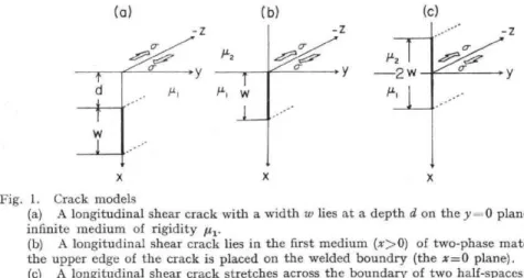
Fig. 1. Crack models
(a) A longitudinal shear crack with a width w lies at a depth d on the y = 0 plane in a infinite medium of rigidity it,.
(b) A longitudinal shear crack lies in the first medium (x>0) of two-phase material, where the upper edge of the crack is placed on the welded boundry (the x=0 plane).
(c) A longitudinal shear crack stretches across the boundary of two half-spaces in contact, where the total width of the crack is 2w.
problem, a constant shear stress a is applied to the crack surface in an un-stressed medium to introduce a longitudinal shear crack with an infinitesimally small thickness.
We treat the following three cases illustrated in Fig. 1. a) The medium is a homogeneous half-space. A longitudinal shear crack with the width of w is buried at the depth d from the free surface (x=0 plane as shown in Fig. 1 (a) ). b) The medium consists of two half-spaces welded together at the plane of x=0. A crack with the width of w is introduced in the first medium (the medium of x>0), and its upper edge is placed on the boundary. The rigidities of the first and second media are denoted by 1,11 and 122, respectively (see Fig. 1 (b) ). c) The medium is the same as in case (b). A crack is extended into the second medium, and its total width is 2w (see Fig. 1 (c) ).
Eshelby et al. (1951) studied the relationship between a pile-up group of slip dislocations and a freely slipping crack, and presented an equivalent distribution of n-parallel discrete dislocations under an external force. Afterwards, Bilby and Eshelby (1968) represented a crack in a linear elastic medium by a continuous distribution, D(x), of infinitesimally small dislocations. The type of displacement discontinuity depends on the type of dislocation involved; the displacement discontinuity for a longitudinal shear crack can be described by screw dislocations, that for a transverse shear crack by gliding edge dislocations, and that for a tensile crack by climbing edge dislocations. We intend here to treat a longitudinal shear crack according to Bilby and Eshelby
(1968).
First consider the general case in which an elastic body contains a continuous distribution D(x) of infinitesimal screw dislocations parallel to the z-axis. A crack is considered to exist in a region E, that is, y=0 and a<x<b. The total dislocation between x and x+dx is D(x)dx. The displacement discontinuity between two surfaces of crack is in the direction of the z-axis and is expressed by
b
Au(x)---
I DW
de
; a
<
x
<b
.
(1)
118 H, ODA and T. HIRASAWA
Since the displacement discontinuity must vanish at both the tips of crack, a condition for D(x) is
D(e) de —0 . (2)
a Further, the displacement field ttc in the medium is written as
ttc(x,
y) = f D($)
u(x e,
y) d$
,
(3)
a
where
u(x–$
, y) is the displacement
in the z-direction
at an observation
point (x, y) due
to a dislocation
existing
at the point
(e, 0) in the region
E.
The stress components
a due to crack formation
are
crii(x,y)
= D(e)
ad•
(X
_e, y) d$
(4)
where
of
i(x–$,
y), (i,j
=x, y, z), are the stress components
at a point (x, y) resulting
from a dislocation
at ($,
0). When an applied
stress
a
t and a frictional
stress
uL on
the crack surface are introduced, equilibrium equations in the cracked region on the fault plane are given by
ai,(x, 0) + cr4 .(x, 0) = a f ii(x, 0); a < x < b (5) Substituting (5) into (4), we have
f•
•
(x
,
0)-0.
fj4.(x,
0)
=
f 13($)
ad.
•
(X
—e,0)
d$
.
(6)
Whensj,sat'and adiare known functions, (6) are reduced to integral equations with respect to D(x). Once the distribution function of infinitesimal dislocations is obtained, the displacement discontinuity, displacement field, and stress field are obtained by
(1), (3), and (4), respectively.
According to Chou and Li (1969), the strain energy released by cracking per unit length of crack is expressed as
AEA(
(Joaziu
dxdo"..(7)J
Ox a
This expression is useful to calculate the change of elastic strain energy in cases (a), (b), and (c).
3. Distribution Function of Displacement Discontinuity
Consider that the medium consists of two elastic half-spaces welded together at the x=0 plane, and that a screw dislocation with unit Burgers vector parallel to the z-axis exists at x= e, e being the distance from the welded boundary. According to Head (1953), the stresses due to the screw dislocation are
THE EFFECT OF MEDIUM HETEROGENEITY UPON THE STATIC DEFORMATION 119 ad x — e +Kx+e ; , = A Yz L (x_e)2+ y2 (X ± e)2+ Y2 x > 0
A [
+K
(x+
62+
y21 x
> 0
,
ad xz ( x62+ y2 (8) — ad=A(1+K) yz( •x0 , xe)2 + y2 axz= — A (1 + K) (x x —+y2 < 0 , where K — /42— A — µ2+,u1 27rFurther, providing that non-vanishing component of the applied stress is only a yAz and there is no frictional stress in the cracked region of a <x <b on the y=0 plane , the equilibrium equation in the region is obtained from (6) as
fb
D(e)
dEKf
ab
D(e)
de _ — 27rcr(9)
J
a x—e
x+e
where gyAz
is assumed to take a constant value a. The second term in the left hand
side of (9) represents the contribution from the image source. This type of integral
equation has been discussed for different values of K by, for example, Chou (1965)
,
Smith (1967),
Barnett (1967), Kuang and Mura (1968),
and others. The existence of
condition (2) in this paper, however,
makes a difference
between the present problem
and those cited above. The cases of K=-1 and —1<K<1 are reduced to cases (a)
and (b), respectively,
and the solution of integral equation will be derived for each case
as follows.
Case (a)
Putting a=d, b=d+w, and K=-1 in (9), the equation to be solved is
d+w
D(e)
d — fd+u, D(E)
d—
27ru
(10)
a x— X+ e
The exact solution that satisfies equation (10) and condition (2) is obtained by means of the inversion theorem formulated by Muskhelishvili (1953). Details of the derivation being omitted, the exact solution for the distribution function D(x) of screw dislocations is given by D ( a(c12 (d +w)2 —2x2) x) =— (11) 4u1-1/(x2d2) ((d + x2) V (x2 —d2) d2) f(d ± x2) where, C p ir(w+d)2+a2_22 (w + d)2 E (k) I F (k)] ,
120 H. ODA and T. HIRASAWA
and
k = -1/(w+d)2—d2 I (w + d) .
Here, F (k) and E (k) are the first and the second complete elliptic integrals. St (11) into (1), the displacement discontinuity is expressed by
Au(x)
= 2a
(w
+
d)
[E(4
p,k)E(k) F (1p,,
k)]
,
F(k)
where, F (lk k) and E (0, , k) are the first and the second incomplete elliptic and ik is given as
arcsm
,(w+d)2—x2 11/2 (w+d)2—d2 For the limiting cases of d/w -*co and dlw—*0,
lim [du (x ,)] = 2aXl(Wx1) ,
diw-oti4141
lim [z1u(x ,)] =2aV22, ditv-*0
0 < x, x—d < w.
The former corresponds to the case in which the crack exists at an the latter to the case where the upper edge of the crack reaches th
The stress fields can be derived analytically from (11) and (4). a y in the un-cracked region of y=0 is given by
a [X2 (d E (k) F (k)] a v— a; x> d, 1/(x2 (x2—d2) (x2 — (d + w)2) a [(d + w)2 E (k)1F (k)— x2] ay, V —a; 0<x<d. (x2 — d2) (x2— (d + w)2)
At a point very close to either of crack edges, the above express: component are approximated by
aV w [1 — E(k)IF (k)](1 + dlw)2 1 ayz aO<E=x—d— cr Yz a V V 2(1 +2d1w)(1 + dlw) 6112 w [(1±diw)2 E (k) (k)— (d w) 1 Substituting (12) integrals, (13) (14)
an infinite depth, and the free surface. The stress component
expressions of the
0 < e — x—d—w<ze) ,
V2 dlw(1+2 dlw) 012 is the distance of the observation point from a
change in elastic strain energy due to insertion
0c 6--- x—d<w , (15) stress (16) where E The (7) as crack of the edge.
THE EFFECT OF MEDIUM HETEROGENEITY UPON THE STATIC DEFORMATION 121
4E(a)
—
on(d+w)2
[k2E(k)
2
1 — 2—F(k)(17) ,u1
For two limiting cases
lim [4E(a)]— w2 (vw-.00 8/11 74.0.2 w2 lim(a)] — d/w-^o Case (b)
Substituting a=0 and b=w into (9), the equation to be solved is D(e) K D(e)
_ 27ra (18) x+e
This kind of integral equation has been solved by Kuang and Mura (1968). The exact solution of (18) with the constraint of (2) is obtainable by a method similar to theirs. The analytical solution for the distribution function D(x) is expressed as
2a 1
D(x)
11
1sinCI-a)
sinh
[a arccoshg2]
2
2a aw
cosh
[a arccoshTPH1
(19)
thsin(-7r—a)i/w2_x2
2 where the parameter a can be determined from the relation,
pi
cos 7ra — P2(20) 41,12-1-th
The displacement discontinuity between the crack surfaces is thus obtained from (1) and (19) as
1
Au(x)—
xsinh
[a arccosh
(—)]
.
(21)
/-11
sin
(2a)
We further have the following expressions for limiting cases with respect to a,
lim [t1u(x)]= lim [du(x)]-= lim [414(x)]= 4a
x arccosh
(—
x)
7rici 2a , Y X(W—x) , lul 2a w"—X2 . 1-11 (22)122 H. ODA and T. HIRASAWA
The case geneous The is given
of a =0 implies a rigid second medium, the space, and the case of a =1 a homogeneous
distribution of stress component cryz in the by substituting (19) into (4) ; case of a=1/2 an half-space of the un-cracked region infinite homo-first medium. of y=0 plane , -Y z= a(1-1-K)
sin
(
71' 2 a )sin (7ra) a(1±K)[cosh
aco
—
cos
(
2sinh ace ;
a)]
1^w2—x2sin
(
2[a arccos
(
a)
sin(7ra)
v-)1
— w < x < 0 , a= ayx a sin sin 7r 2 a -a + a awsin
(-7r
2a
)i/ x2
—
w2
cos
[a arccos
w x
)1
W < X , (23) where, sinh w= [(L:
)2- 1]1/2
At a point component in is the proximity approximatelyof the crack tip in the expressed as
second medium the above stress
,.C..._J 4.. . YZ
a (1 + K)
2 sin 2
cr)
sin
(7-
tu)[(1—
a)
(
2wE
)
—2
cos
(
7r _ a2
)]
(24)where E is the distance of the point from the tip of crack. stress component at a point very close to the crack tip in the mated by
a al/ w 1
ar= .Y2. —a .
V'2sin(
2na)"12
On the other first medium hand, the is approxi-(25)The change of the strain energy per unit length of the crack is obtained from (7)
as 4E(') ---a2a2w27r
4/21
[
sin 7r — a 2 2)1
(26)THE EFFECT OF MEDIUM HETEROGENEITY UPON THE STATIC DEFORMATION 123
g2w2
Ern [LEO)] = 7rµ„
lim [11E(b)] —aheArr, 8 t12 llm [ZIE(b)]cr2w27 4 ,u, • Case (c)
When the distribution functions of infinitesimal diF. x>0 and x<0 are denoted by D1(x) and D2(x), respectivE be solved are
1 D1M de+K f
de+(K+1)D2(e)
ox—e Jo x+e J x_e ro D2() Di(e)
Jx2—edeKJo
-w-wx+D +(l—K)f
ox_ede—
Using D1(x) and D2(x), the displacement discontinuity in
_Ev
4u(x) = D2(e)dE; —w < x < 0,
x
w
z1u(x)= Di(e)de; 0 < x < w
x Since the displacement discontinuity should be continuoi
the two media, we find the following relation,
D„(e)de + D2(e)de = 0 .J
o -w
This constraint is equivalent to the condition (2) which displacement discontinuity at each of crack tips. With t the exact solution of distribution function for (28) with (;
--2ax
22a(1 1
Di(x) =——
—)[(1±K)
a
p21/W2 x2 th P2 (1+K)w n(1—K)x ; 0 < x < w 2-1/w2 x2D2(x)
= —22g(1—K)
(1
1y
1121/aixlW2—X2thIL7t711X1
I
; —W < X < w2_x2 21/702_x2 (27)simal dislocations in the domains respectively, the intergral equations D2(e) —27ra
1)jde
x—e pi Di(e) 27ra C) • x—e /22discontinuity in each medi
; x > 0 , x < 0 . urn is e: (28) of to expressed as (29)
continuous at the boundary between
(e)de— 0 . (30)
(2) which requires the vanishment of 3. With the aid of inversion theorem 28) with (30) is
)[(1+K)
arccosh(—:)
0 < x < w , (31)—1
—1yarccosh(--W
)
eatth x —w < x < 0 .124 H. ODA and T. HIRASAWA
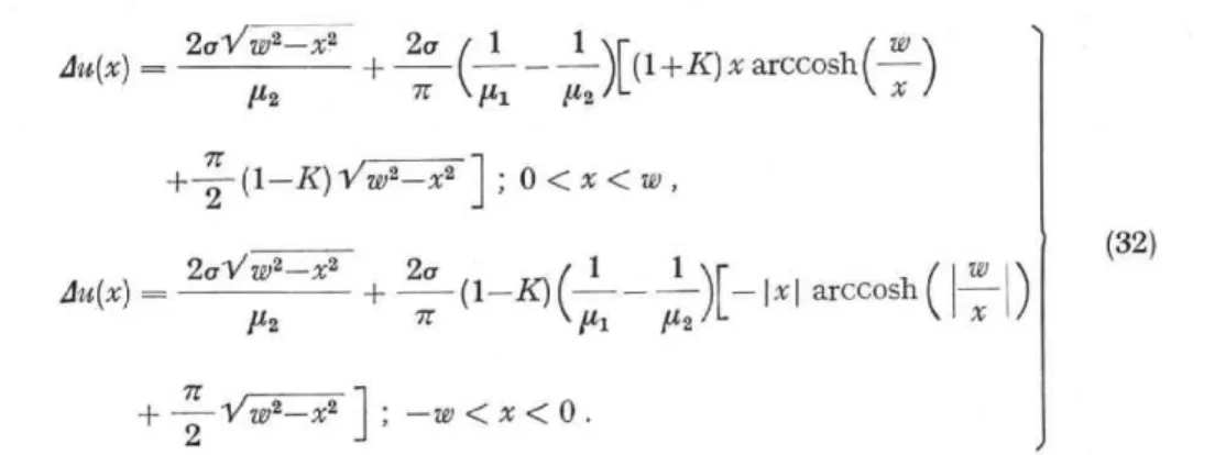
The displacement discontinuity in each medium is calculated
414(X)
—
2al/w2—x2
+ 2a
( 1 —1
)[(1
± K)
x arccosh.(
1427r1-11µ2 7r+ 2(1—K)Vw2—x2
1
; 0
<
x
<
w
,
2al/w2—x2is calculated from (29) and (31) as
w ) x )
du(x)
7r ±
P2
+ —2a
n(1—K)
(I— i )[—
4a1 P2Ix
I
arccosh
-Vw2_ x2]
-w < x < 0 .w x
(32)
This solution has a singularity in the stress component ax, at the intersection of the fault plane with the welded boundary. This seems to be a mathematical consequence of the constraint that the displacement discontinuity should be continuous over the fault plane. The released energy per unit length of the crack is evaluated from (7) as
7rg2w2 1 1 K R(1—K)]
(33) AE(6) — 2 +0.2w2
µ2P1 P2 IL7r4
4. Results
The analytical solutions of the present problem were given in the preceding section. The numerical results calculated from the analytical expressions will be presented in this section separately for the cases (a), (b), and (c).
Case (a)
Let us introduce the following dimensionless quantities corresponding to the distance, x, from the free surface on the fault plane and the displacement discontinuity, du(x), on the slip plane ;
X -= (x—d)fw ,
4U 2it a1w AU
(34)
where d is the depth of the upper edge of crack from the surface, w the fault width, a a constant shear stress applied to the slip surface, and y, the rigidity. Thus, X is the ratio of the distance of a point on the fault plane from the upper crack edge to the crack width.
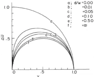
Fig. 2 illustrates AU as a function of X for different values of dlw. While the displacement discontinuities for cases of dlw>1 are almost identical with that for the crack in an infinite medium, those for cases of 0<dlw<1 are affected by the existence of the free surface. It is seen in the figure that the average value of AU becomes larger as the crack top approaches the free surface. The displacement discontinuity for the
THE EFFECT OF MEDIUM HETEROGENEITY UPON THE STATIC DEFORMATION 125 1.0 D 4 .5 Fig. 2. Illustration of different values of E X E < C L.J 5 0 0 . 5 1. C d/w 0 .5 1.0 X
the displacement discontinuity across the djw. The dimensionless quantities of AU
d/w=0.05 d/v 0.1 dive. 0.5 =0 .0 0 =0 .01 =0 .05 =0 .10 =0 .50 =co
crack surface for case and X are defined by
(a) (34) for 1 1 cryz/cr 7 3 Fa uli d/w= 0.01 d/w= 0.05 d/w- 0.5 1 1 1 5I 1 0 .5 1.0 .041 -.03 -.02 -.01 0 1.00 1.01 1.02 1.03 1.04 d /w X
Fig. 3. Variations of X., 4 U,,,, Fig. 4. Variation of the shear stress cry, in the un-cracked
and E„ with respect to clfw in region on the fault plane in case (a) with respect to X
case (a). defined by (34).
X.; the value of X at which AU takes its maximum value. 41U.; the maximum value of 4 U.
En; the dismenisionless tity for the released energy as
defined by (35).
extreme case of dlw---0 is identical with that for the crack with the width of 2w in an infinite medium. This is consistent with the Walsh's result (1968) for a vertical strike-slip fault.
Let AU„, and X. be the maximum value of 4U and the value of X corresponding to 4U„„ respectively. Figs. 3(a) and (b) show the variations of X„, and AU,, with respect
126 H. ODA and T. HIRASAWA
to dlw. Since the numerical values of X. and LIU. both take 0.5 in the case of a crack in an infinite medium, the effect of free surface is considered negligible in cases of dlw> 1. In the cases of 0<d/w<0.1, however, the effect becomes significant. As the crack top approaches the free surface, AU. increases in its value and the point of X „, approaches the crack top. This is in accordance with the numerical result presented by Kasahara (1964). The significant effect of free surface is thus expected only for the case in which a crack exists very close to the free surface.
It is important to discuss the change of the elastic strain energy, because the energy required to produce a crack is provided by the decrease in elastic strain energy stored in the medium. Fig. 3(c) illustrates the dimensionless quantity Et, of the released
energy AE(a) per unit length of the crack with respect to dlw, that is,
En= 4t14E(a)1(7ra2w2) (35)
where Et, is normalzied so that its value takes unity for the case of dlw=0. It varies very rapidly in the range of dlw less than 0.1. When the crack top reaches the free surface, the amount of released energy is equal to a half of that in the case of a crack with the width of 2w in an infinite medium. This result agrees with those by Knopoff (1958) and by Burridge and Knopoff (1966).
Next we examine the behavior of stress component ay, on the fault plane (y=0 plane). The effect of the existence of free surface on the stress component is detectable, in practice, only for dlw less than unity, similarly to the case of displacement discontinuity. Fig. 4 shows the stress concentration near the crack tips for small values of dlw, where the left figure corresponds to the upper un-cracked region and the right to the lower one on the fault plane. As a whole the values of apla are larger for smaller values of dlw on both the regions. It is further read from the figure that the stress intensity, or, consequently, the width of the region where the value of ay,/a exceeds a critical value, is larger for the upper crack edge (left figure) than that for the lower one (right figure). As shown by (16) in the previous section, ay, is proportional to 012 both for the upper (e/w--.X) and for the lower (Elw=X-1) crack edges. This result is different from that in case (b) as will be discussed later.
Case (b)
In the present case the dimensionless quantitil
X a_--.x/w ,
AU 2
aw Au , where it, is the rigidity of the first medium in whic discontinuity in a dimensionless form is illustrated ii The figure indicates that the displacement disconti for a softer second medium (the medium X<0). I infinity, AU as a function of X exactly agrees with
quantities are defined as
(36)
rst medium in which a crack exists. The displacement form is illustrated in Fig. 5, taking iti/#2 as a parameter. isplacement discontinuity becomes larger on the whole
medium X<O). In the limiting case as 4tc1/p2 tends to exactly agrees with that for the particular case of
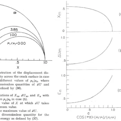
THE EFFECT OF MEDIUM HETEROGENEITY UPON THE STATIC DEFORMATION 127 1.0 .5 3.85 1.00 P-. IiL,= 0.00 E x 5 o H 0 5 1.0 5 X
Fig. 5. Illustration of the displacement dis- continuity across the crack surface in case1.0
(b) for different values of ittildu,, where
the dimensionless quantities of AU and
X are defined by (36).
Fig. 6. Variations of Xm, AUm, and En with
respect to in case (b). .5
Xm; the value of X at which AU takes its maximum value.
AUm; the maximum value of AU. En; the dimensionless quantity for the
released energy as defined by (37).
0 in case (a). Let us define AU. and X. as the m[ of X giving AU.. Figs. 6(a) and (b) show Xm and determined by the relation (20), and a =0, 1/2, 1 cc tively. Fig. 6(b) clearly indicates that the value of It is further seen from Fig. 6(a) that the maximum moves from the middle point of the crack in the ca for 1u14112> 1, or toward the crack bottom for ,u1/,u2<
The dimensionless quantity for released energy
E.= 4p14E(b)1(71-0•27, This function of a is illustrated in Fig. 6(c). As ex: Fig. 6(b), the released energy increases as the sec, amounts of energy change in the limiting cases of 8/72 times and twice as large as that in the case I exists in an infinite medium of rigidity pi
Fig. 7 shows the concentration of stress compon edges on the fault plane. The dependence of the st ratio is seen from the figure, where a =0.5 me. (121=1,12), and a=0.2 and 0.7 imply y1 <,u2 and pi>
(a)
(b)
b) show X. and AU. id a =0, 1/2, 1 correspc that the value of AU. i at the maximum point e crack in the case of / bottom for /t
released ener is def = 4,AE(b)1(71-a2w2) Fig. 6(c). As expected -eases as the second it
of stress component ayz ndefice of the stress co-here a=0.5 means
pi<p, and pi>p2.
(C) 0 .5 1.0 a C 0 S(7ra )- (4, -1-1)/(1-/#11,)
maximum value of AU and the value id AU. with respect to a, where, a is correspond to /111/22=0, 1, c/3 , respec-Df AU. increases with an increase in a. m point of displacement discontinuity case of 21/112=1 toward the crack top 22<1-
defined by
720) (37)
expected from the behavior of z/U„, in econd medium becomes softer. The of tu1du2=0 and cc, respectively, are where a crack with the same width
onent a in the vicinities of the crack yz stress concentration upon the rigidity neans a homogeneous infinite space >1... In the first medium the curve
128 H. ODA and T. HIRASAWA
-/5 -
Phas First Phase -io _ a=07 1=0.5 Crzy/Cr C1=05 .0.2 '0.7 a=0.2 -5 Fault - 0 06 -0.04 - 0.02 0 " 1.00 1.02 1.04 1.06 X
Fig. 7. Variation of the shear stress (Ty, in the un-cracked region on the fault plane in case (b) with respect to X defined by (36). The parameter a is determined by the relation, cos na= (t12-111)1(1z2+Pi)•
of gyzia having a smaller value of a, roughly speaking, shifts toward the lower side. In the second medium, on the other hand, the situation is complicated, and the three curves interesect with one another. A careful examination of the figure reveals that the case of a=0.7 (,a1> ,u2) shows the highest stress concentration in close proximity of the crack edge. This complex behavior of ay, results from the fact that ay, in the second medium varies in proporition to 6—a near the crack edge, whereas it varies as e-1-12 in the first medium, as found in (24) and (25). Thus, while the pattern of stress concentration in the first medium is independent of the rigidity ratio, the concentra-tion in the second medium depends on the ratio. It is concluded for the case of yi> y2, therefore, that the stress intensity in close proximity of the crack edge is greater in the second medium than that in the first medium.
Case (c)
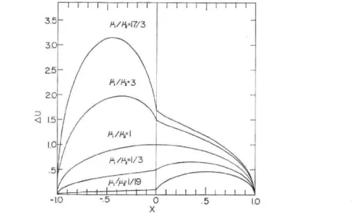
Fig. 8 depicts the displacement discontinuity in a dimensionless form with respect to X for different values of rigidity ratio, where X and AU are difined in (36). The average amount of slippage increases monotonously with an increase in 1u1 Jµ2. Together with the result of distribution pattern of slippage these results are easily understood, at least qualitatively, from the physical intuition, because the applied shear stress is assumed to be uniform over the entire crack surface. Fig. 9 illustrates the released energy per unit length with respect to a, where the dimensionless Et, and the parameter a are defined by
En= 2Ena,/(7ru2w2) ,
a2p1/(tti+ z2) • (38)
The value of E. becomes unity when pi is equal to /22. In the limiting case as hip, tends to infinity, E. also tends to infinity because of the divergence of AU in the second medium. Since the pattern of stress concentration in the present case shows no particular features and can be estimated from the results in cases (a) and (b), its illustration is omitted.
THE EFFECT OF MEDIUM HETEROGENEITY UPON THE STATIC DEFORMATION 129 Fig. 3.5 3.0 2.5 2.0 <1 1.5 I0 .5 /-Li/i12=1 PI/P.2=1/3 11,64E1/19 -1.0 -.5 X0 .5 1.0
8. Illustration of the displacement discontinuity across the crack surface in case (c) for different values of c11,u2, where the dimensionless quantities dU and X are defined by (36).
Imagine the case where the edge of a crack reaches the boundary plane between two different media but does not penetrate the boundary. In order to examine the possibility of crack penetration into the second medium, we take the ratio of the released energy given by (33) for case (c) to that by (26) for case (b), where the crack width 2w is replaced by w in (33) so that the cracks have the same width for both the cases. The ratio is given by
AE(c)
( 21.ay:
2
[sin
( ciA
2
L1E(b) 211,a2 a271- 1,127r4
+ (1
—K)1
. (39)
3.2 2.4 c I . 6 0 . 8 0 0,4 0.8 1.2 1.6 2.0 a
Fig. 9. Variation of En as a function of a in case (c), where, a =2y11(,u,+ ,u2), and En is sionless quantity for the released energy as defined by (38).
dimen-130 H. ODA and T. HIRASAWA
The value of this ratio is larger than unity for the case ,u11,(42>1, and vice versa. This implies that when the second medium is softer than the first, the strain energy released by cracking in both the media is larger than that by cracking only in the first medium . From this and the result of stress concentration in close proximity of the crack edge obtained for case (b), the possibility of crack penetration into the second medium is higher than that of crack enlargement to a deeper depth of the first medium . When the second medium is harder, the reverse is expected .
5. Conclusions
In this paper a theoretical study were made on the static deformation due to a longitudinal shear crack in the medium of two different elastic half-spaces in contact as well as in a semi-infinite medium. It was found in general that the medium heterogeneity represented by the existence of free surface or of boundary plane between two different elastic media greatly affects the distribution of displacement discontinuity across the crack surface, the elastic strain energy released by crack formation, and the pattern and intensity of stress concentration in the vicinity of the
crack edge on the fault plane.
The first problem we studied is for a longitudinal shear crack lying at a depth in a semi-infinite medium, which is called case (a). When the ratio, cllw, of the depth of the crack top from the free surface to the crack width is smaller than about 0.1, the effect of the existence of free surface is significant upon the distribution of displacement discontinuity across the crack surface and upon the concentration of the shear stress in the un-cracked region on the fault plane. In the limiting case where the upper edge of crack reaches the free surface, the distribution function of dislocations becomes identical with that for the crack with the width of 2w in an infinite medium. When cilw is greater than unity, the distribution function is sufficiently well approximated by that for the crack in an infinite medium. The strain energy released by introduction of a crack as well as the intensity of the stress concentration near the upper edge of crack increases with a decrease in the depth of the crack top. This may support the existence of the energetic event of break-out phase in the case of shallow earthquakes . The break-out phase was first found by Savage (1965) in his model experiment , and discussed by Hirasawa (1965) in his study of the Niigata earthquake of 1964. How-ever, a definite evidence has not yet been found for its reality.
The second problem of case (b) is for a longitudinal shear crack in a two-phase material, where the upper edge of the crack in the first medium reaches the boundary plane between different elastic media. The amount of slippage on the crack surface and the strain energy released by crack insertion increase as the second medium becomes softer than the first. Let E be the distance of a point from the crack edge in the un-cracked region on the fault plane. The shear stress near the edge is proportional to 6-1/2 in the first medium, while it is proportional to E-a in the second medium , where a is determined by the relation, cos na=(1,12--iui.)1(,u2+ and lui and ,u, are the rigidities of the first and the second media. Thus, the stress concentration in the second
THE EFFECT OF MEDIUM HETEROGENEITY UPON THE STATIC DEFORMATION 131
medium shows a pattern quite different from that in the first. It is further concluded that the intensity of the stress concentration in the vicinity of the crack edge is significantly higher in the second medium than that in the first for the case of µi/u2> 1. The thrid problem of case (c) is for a longitudinal shear crack lying over two different elastic media. It was found that the amount of slippage on the crack surface is greater in the softer material than that in the other. Let us suppose the case in which one of crack edges has reached the boundary between two different media but not yet penetrated the boundary to the second softer medium. Considering the results of the released energy and the stress concentration, it is more likely for the crack to penetrate the boundary into the second medium rather than to enlarge to a deeper depth in the first medium. It should be noted that a singularity of the shear stress component a„ acting on the boundary plane is found to exist at the intersection of fault plane and boundary plane for case (c). This may suggest the possibility of producing a secondary fault on the boundary, forming a conjugate fault together with the main fault. The present model of a longitudinal shear crack apparently simulates a strike-slip fault. The present result is applicable, however, also to some problems for dip-slip fault. For example, imagine the case in which there is a steeply dipping geological boundary, and the edge of dip-slip fault reaches or penetrates the boundary. It is inferred from the present result that the secondary fault is possibly produced on the geological boundary. As an example of actual cases, Tsuya (1946) and Ando (1974) reported that the FukOzu fault has a secondary fault which occurred along the boundary between the different rock faces during the occurrence of the Mikawa earthquake of 1945.
Acknowledgments We wish to express our thanks to Prof. Z. Suzuki for his instructive suggestion and encouragement during the course of this study. We are indebted to Drs. H. Hamaguchi and K. Yamamoto and Messrs. J. Koyama and T. Sato for their helpful discussions.
References
Ando, M., 1974: Faulting in the Mikawa earthquake of 1945, Tectonophysics, 22, 173-186. Barnett, D.M., 1967: The effect of shear modulus on the stress distribution produced by a
planer array of screw dislocations near a bi-metallic interface, Acta Met., 15, 589-594. Bilby, B.A. and J.D. Eshelby, 1968: Dislocations and the theory of fracture, Fracture vol. 1,
edited by H. Liebowitz, 99-182, Academic press, New York.
Burridge, R. and L. Knopoff, 1966: The effect of initial stress or residual stress on elastic energy calculations, Bull. Seism. Soc. Am., 56, 421-424.
Chinnery, M.A., 1961: The deformation of ground around surface faults, Bull. Seism. Soc. Am., 51, 355-372.
Chou, Y.T., 1965: Linear dislocation arrays in heterogeneous materials, Acta Met., 13, 783.
Chou, Y.T. and J.C. Li, 1969: Theory of dislocation pile-up, Mathematical theory of dislocations, edited by T. Mura, 116-177, Amer. Soc. Mech. Eng., New York.
Eshelby, J.D., F.C. Frank, and F.R.N. Nabarro, 1951: The equilibrium of linear arrays of dislocations, Phil. Mag., 42, 351-364.
132 H. ODA and T. HIRASAWA
Hirasawa, T., 1965: Source mechanism of the Niigata earthquake of June 16, 1964, as derived from body waves, J. Phys. Earth, 13, 35-66.
Kasahara, K., 1959: Physical conditions of earthquake fault II, Bull. Earthq. Res. Inst., 37, 39-51.
Kasahara. K., 1964: A strike-slip fault buried in a layered medium , Bull. Earthq. Res. Inst., 42, 609-619.
Knopoff, L., 1958: Energy released in earthquake, Geophys. J., 1, 44-52.
Kuang, J.G. and T. Mura, 1968: Dislocation pile-up in two phase materials , J. Appl. Phys., 39, 109-120.
Lachenbruch, A.H., 1961: Depth and spacing of tension cracks, J. Geophys. Res., 66, 4292.
Mansinha, L. and D. Smylie, 1971: The displacement fields of inclined faults, Bull. Seism. Soc . Am., 61, 1433-1440.
Maruyama, T., 1964: Statical deformations in an infinite and semi-infinite medium, Bull. Earthq. Res. Inst., 42, 289-368.
Muskhelishvili, N.1., 1953: Some basic problem of the mathematical theory of elasticity, P. Noordhoff, Groningen, Holland.
Sato, R. and M. Matsu'ura, 1973: Static deformation due to fault spreading over several layers in a multi-layered medium, J. Phys. Earth., 21, 227-249.
Savage, J.C., 1965: The stopping phase on seismograms, Bull. Seism. Soc. Am., 55, 47-58. Savage, J.C. and L.M. Hastie, 1966: Surface deformation associated with dip-slip fault , J.
Geophys. Res., 71, 4897-4904.
Smith, E., 1967: Screw dislocation arrays in heterogeneous materials, Acta Met. , 15, 249-252. Tsuya, K., 1946: A remarkable earthquake fault formed during the Mikawa earthquake of
January 13, 1945, Bull. Earthq. Res. Inst., (in Japanese with English abstract), 24,
59-76.
Walsh, J.B., 1968: Mechanism of strike-slip faulting with friction, J. Geophys. Res. , 73, 761— 776.
Weertman, J., 1964: Continuum distribution of dislocations on faults with finite friction, Bull. Seism. Soc. Am., 54, 1035-1058.