純チタン製口腔インプラント体とチタンジルコニウム合金製口腔インプラント体のMRIによる金属アーチファクトの比較
6
0
0
全文
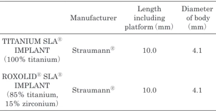
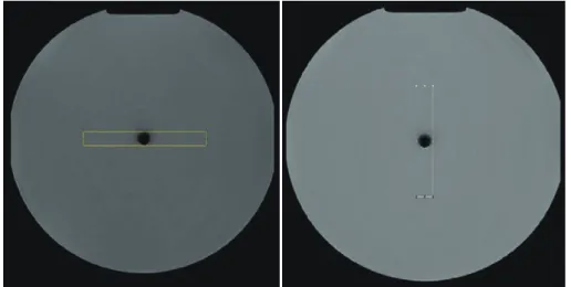
(2) 小松. 歯科放射線 2021 年 3 月. 2.撮像法および撮像条件. 対象および方法. 撮像条件は,本学附属病院で頭頸部領域に使用している. 1.使用機材. 撮像条件に従った。各シークエンスのパラメーターは,. MRI 装置は Philips 社製の Intera Achieva 1.5T(Philips. Turbo Spin echo(TSE) に よ る T1 強 調 像(TR 586ms, TE 9 ms,スライス厚 6 mm,マトリックスサイズ 256×. medical systems, Netherland)と SENSE Head 8ch coil を 使用した。ファントムは直径約 20cm の円柱体のアクリル. 256,FOV 230mm,バンド幅 381.4Hz/pixel,ETL 3,NSA 2) ,TSE による T2 強調像(TR 7349ms,TE 120ms,スラ. 容 器 を 使 用 し, 容 器 内 部 を ベ ビ ー オ イ ル(Johnson &. イス厚 6 mm,マトリックスサイズ 256×256,FOV 230mm,. Johnson, Tokyo)で満した。使用したインプラント体は TITANIUM SLAⓇ IMPLANT お よ び ROXOLIDⓇ SLAⓇ. バンド幅 120.8Hz/pixel,ETL 15,NSA 3) ,Short Tau In-. IMPLANT(Straumann Japan, Tokyo)であり,詳細は 表に示す通りである(Table 1)。インプラント体は,ファ ントム内に設置した直径約 10.0mm のアクリル製の円柱 棒の先に固定し,円柱棒の先がファントムの中央になるよ うに設置した。尚,ファントムの設定は静磁場方向と平行 になるように設定した(Figure 1)。 Table 1 Implants length and diameter by the manufacture Manufacturer. Length Diameter including of body platform(mm) (mm). TITANIUM SLAⓇ IMPLANT (100% titanium). StraumannⓇ. 10.0. 4.1. ROXOLIDⓇ SLAⓇ IMPLANT (85% titanium, 15% zirconium). StraumannⓇ. 10.0. 4.1. Figure 1 Photograph of the phantom and dental implants a:Static magnetic field The implant body was set parallel to the direction of the static magnetic field.. Figure 2 The images show the phase- and frequency-encoding direction settings a:Phase-encoding direction, b:Frequency-encoding direction A:The phase-encoding direction was set in the right-left(R-L)direction and the frequency-encoding direction was set in the anterior-posterior(A-P)direction on turbo spin echo T1-weighted imaging, turbo spin echo T2-weighted, and short tau inversion recovery. B:The phase-encoding direction was set in the A-P direction, and the frequencyencoding direction was set in the R-L direction on single shot echo planar imaging diffusion-weighted imaging.. 43.
(3) 歯科放射線 60 巻 2 号. 小松. version Recovery 像(STIR 像)(TR 2500ms,TE 60ms,. mm 単位で求めた。測定は,2 名の歯科放射線科医が Ti. 230mm,バンド幅 301.9Hz/pixel,ETL 15,NSA 3,TI. 条件ごとに計 10 回 FWHM の測定を行った。. 180ms),Single Shot Echo Planar Imaging(SSEPI)に. 4.統計分析. よ る Diffusion Weighted Imaging(DWI)(TR 4936ms,. 統計分析は,Mann-Whitney U test を用いて撮影条件. スライス厚 6 mm,マトリックスサイズ 256×256,FOV. 製インプラント体および Ti-ZrO2 製インプラント体を撮影. TE 69ms,スライス厚 6 mm,マトリックスサイズ 256×. ごとに Ti 製インプラント体と Ti-ZrO2 製インプラント体. 256,FOV 230mm,バンド幅 19.3Hz/pixel,b 値 1000s/. の FWHM の比較を行った。統計分析ソフトには SPSS. mm )とした。また,撮影時の位相エンコード方向と周. version 21Ⓡ(IBM Japan, Tokyo) を 用 い,p < 0.05 を. 波 数 エ ン コ ー ド 方 向 の 設 定 は T1 強 調 像,T2 強 調 像,. もって有意性を示すものとした。また,2 名の歯科放射線. STIR 像では位相エンコード方向を right-left(R-L)方向,. 科医から得られたそれぞれの FWHM の一致率は,intra-. 周波数エンコード方向を anterior-posterior(A-P)方向. class correlation coefficients(ICC) を 用 い た。 そ の 際,. 2. とした。DWI では位相エンコード方向を A-P 方向,周波. ICC が,0.0-0.20 をわずかに一致,0.21-0.40 をまずまず. 数エンコード方向を R-L 方向とした(Figure 2)。. の一致,0.41-0.60 を中等度の一致,0.61-0.80 をかなり. 3.測定方法. の一致,0.81-1.00 をほぼ完全に一致とした。. ア ー チ フ ァ ク ト の 分 析 に は,ImageJ Ver.1.52a(National Institutes of Health, USA) を 用 い た11。 ア ー チ ファクトの評価スライスは,アーチファクトが最大径で発 生すると考えられるインプラント体の最大径を含むスライ スで評価を行った(Figure 3)。アーチファクトは,評価 スライス上でアーチファクトの最大径を含む領域に大きさ. H10mm×W70mm の関心領域(Region of Interest;ROI) を設定した。また,アーチファクトの大きさを多方向から 精査する為に,測定方向を位相エンコード方向と周波数エ ンコード方向のそれぞれに ROI を設定した(Figure 4)。 次に,ROI 内の信号強度を短辺方向に平均化し,その平均 値の長辺方向のプロファイルラインを求めた(Figure 5) 。 そして,アーチファクトが生じていない部位のプロファイ ルラインの平均値を求め,基準値とした。基準値から. Figure 3 Evaluation slice of metal artifacts The metal artifacts were measured on an axial slice that demonstrated the maximal area of the implant body.. 50%信号が低下した部位のプロファイルラインの幅を半 値幅(Full Width at Half Minimum(FWHM))として. Figure 4 Region of interest(ROI)used to measure the size of artifacts The ROIs were placed for the measurement of metal artifacts in the phase- and frequency-encoding directions.. 44.
(4) 小松. 歯科放射線 2021 年 3 月. Figure 5 Procedure to measure the full width at half maximum(FWHM)of the profile line a:Baseline was set for the average of profile line in the region with no influence of metal artifacts. b:FWHM was measured between baseline(a)and minimum value(c)of the artifact.. 結 果 本 研 究 で 得 ら れ た 実 際 の Ti 製 イ ン プ ラ ン ト 体 と TiZrO2 製インプラント体のアーチファクトの MR 画像を示 す(Figure 6)。シークエンスごとの画像における Ti 製イ ンプラント体と Ti-ZrO2 製インプラント体のアーチファク トの FWHM の平均値を位相エンコード方向(Table 2) と周波数エンコード方向(Table 3)のそれぞれで測定し 比較した。また,測定された FWHM の測定者間の ICC は,0.771 であった。 1.T1 強調像の FWHM T1 強 調 像 に お け る,Ti 製 イ ン プ ラ ン ト 体 お よ び TiZrO2 製インプラント体の FWHM は,位相エンコード方. Figure 6 Images of metal artifacts induced by Titanium (Ti)and Titanium-Zirconium(Ti-ZrO2)dental implants Metal artifacts were measured in each imaging sequence.. 向 で 各 々 6.96±0.01mm,6.79±0.01mm で あ り 両 者 に. 有意差はみられなかった(p > 0.05)。また,周波数エン. コ ー ド 方 向 に お い て は 7.01±0.01mm,6.84±0.01mm. ンプラント体の FWHM は,位相エンコード方向で各々. であり位相エンコード方向と同様に両者に有意差はみられ. 6.56±0.01mm,6.45±0.01mm であり両者に有意差はみ. なかった(p > 0.05)。. られなかった(p > 0.05) 。また,周波数エンコード方向に. 2.T2 強調像の FWHM. おいては,6.60±0.01mm,6.49±0.01mm であり位相エ. T2 強調像では,Ti 製インプラント体および Ti-ZrO2 製 インプラント体の FWHM は,位相エンコード方向で各々. ンコード方向と同様に有意差はみられなかった(p > 0.05) 。. 7.97±0.01mm,7.07±0.01mm であり,Ti-ZrO2 製イン. 4.DWI の FWHM. 意に小さかった(p < 0.05)。また,周波数エンコード方. ラント体の FWHM は,位相エンコード方向で各々 11.23±. 位相エンコード方向と同様に Ti-ZrO2 製インプラント体の. ト体の FWHM は Ti 製インプラント体と比較し有意に小さ. DWI では,Ti 製インプラント体および Ti-ZrO2 製インプ. プラント体の FWHM は Ti 製インプラント体と比較し有. 向 に お い て も 8.04±0.01mm,7.13±0.01mm で あ り,. FWHM と Ti 製インプラント体の間に有意差がみられた. 0.02mm,9.64mm±0.01mm であり,Ti-ZrO2 製インプラン. かった(p < 0.01) 。また,周波数エンコード方向において. も,11.14±0.02mm,9.55±0.01mm であり,位相エンコー. (p < 0.05)。 3.STIR 像の FWHM. ド方向と同様に Ti-ZrO2 製インプラント体の FWHM は Ti. STIR 像では,Ti 製インプラント体および Ti-ZrO2 製イ. 製インプラント体と比較し有意に小さかった(p < 0.05) 。 45.
(5) 歯科放射線 60 巻 2 号. 小松 Table 2 FWHM of phase-encoding direction measured with each MRI sequence for Titanium(Ti)and Titanium-Zirconium(Ti-ZrO2) FWHM±SD(mm) TITANIUM SLAⓇ IMPLANT (100% titanium). ROXOLIDⓇ SLAⓇ IMPLANT (85% titanium 15% zirconium). T1WI. 6.96±0.01. 6.79±0.01. T2WI. 7.97±0.01. STIR. 6.56±0.01. DWI. 11.23±0.02. 7.07±0.01 *. 6.45±0.01 9.64±0.01. **. p < 0.05 **p < 0.01. *. Table 3 FWHM of frequency-encode direction measured with each MRI sequence for Titanium(Ti)and Titanium-Zirconium(Ti-ZrO2) FWHM±SD(mm) Ⓡ. TITANIUM SLA IMPLANT (100% titanium). ROXOLIDⓇ SLAⓇ IMPLANT (85% titanium 15% zirconium). T1WI. 7.01±0.01. 6.84±0.01. T2WI. 8.04±0.01. STIR. 6.60±0.01. DWI. 11.14±0.02. 7.13±0.01. *. 6.49±0.01 9.55±0.01. ** *. p < 0.05 **p < 0.01. 1.インプラントの材質の違いにおける磁化率の大きさ. 考 察. の検討. 本研究において,Ti-ZrO2 製インプラント体の FWHM. 全てのシークエンスにおいて Ti-ZrO2 製インプラント体. は Ti 製インプラント体と比較し,位相エンコード方向お. の FWHM は Ti 製インプラント体と比較し小さかった。. よび周波数エンコード方向で T2 強調像(p < 0.05)と. Smeets らの報告においても,ジルコニウムの含有量が多. DWI(p < 0.01)で有意に小さく,T1 強調像(p > 0.05). いインプラント体程磁化率アーチファクトが少ない事が報. と STIR 像(p > 0.05)では有意な差はなかった。MRI. 告されており14,常磁性体の Ti と Zr の磁化率は Zr の方. 検査におけるアーチファクトは,金属の磁化率が関係して. が小さいことが示唆された。. おり,磁化率が大きい金属は磁化率の小さい金属と比較し,. 2.撮影シークエンス間におけるアーチファクトの検討. MR 画像に大きな影響を与える5。磁性体金属は大きく分. 撮像シークエンス間で比較した場合の Ti 製インプラン. けて強磁性体金属,常磁性体金属,反磁性体金属の 3 つ. ト体と Ti-ZrO2 製インプラント体の FWHM の大きさは,. に分類され,強磁性体金属は MRI 検査を行う上で,画像. DWI,T2 強調像,T1 強調像,STIR 像の順で大きかった。. 評価に大きな影響を与えるが,反磁性体金属はほとんど影. T1 強調像と STIR 像では Ti-ZrO2 製インプラント体と Ti. 響を与えないとされる12,13。一方で,Ti と Zr は常磁性体. 製インプラント体との間で有意な差はなく,T2 強調像,. 金属に分類され,撮影条件によっては,MRI 検査を行う. DWI では,Ti-ZrO2 製インプラント体は Ti 製インプラン. 上で障害となる。よって,本研究では MRI 検査における. ト体と比較して有意に小さかった。本研究の TE は T2 強. Ti 製インプラント体と Ti-ZrO2 製インプラント体から発. 調像,DWI,STIR 像,T1 強調像の順で長く設定されて. 生するアーチファクトの大きさを比較した。. いる。TE は励起 90°パルスからデータサンプリング時間 の中央までの時間であり,TE が短くなると磁化率効果に よる位相分散の影響が小さくなる。この為,磁化率アーチ 46.
(6) 小松. 歯科放射線 2021 年 3 月. ファクトの影響が減少する。本研究では,TE が比較的短. 謝. く設定されている T1 強調像,STIR 像では Ti 製インプラ. 辞. ント体と Ti-ZrO2 製インプラント体の FWHM の差が近接. 本研究に際し,ご協力頂いた本学附属病院診療放射線技師の前. し有意な差が生じなかったと考えられる。比較的 TE が長. 原正典氏,およびインプラント体をご提供いただいたストローマ ン・ジャパン株式会社の関係者の皆様方に深く感謝致します。. く設定されている T2 強調像,DWI では Ti 製インプラン ト体と Ti-ZrO2 製インプラント体の FWHM の差が増大し. 文. 有意な差が生じたと考えられる。また,DWI は T2 強調 像より大きくアーチファクトが生じた原因として,SSEPI によるものが考えられる。SSEPI は,一回の励起 90°パ ルスと励起 180°パルスのみで,多くの echo 信号を取得 し k 空間の全てのラインに対してサンプリングを行う為, 位相のずれおよび位相分散が蓄積されやすく,位相方向に 大きなアーチファクトが生じ易いとされている15。この為, DWI は T2 強調像に比べアーチファクトが大きく生じた と考えられる。 3.位相エンコード方向と周波数エンコード方向におけ るアーチファクトの検討 全てのシークエンスにおいて,位相エンコード方向と周 波数エンコード方向共に Ti-ZrO2 製インプラント体のアー チファクトの FWHM は,Ti 製インプラント体と比較し 小さかった。また,T1 強調像,T2 強調像,および STIR 像では周波数エンコード方向の FWHM は位相エンコード 方向の FWHM と比較し,やや大きかった。その理由とし て,周波数エンコードは位相エンコードの後に行い励起パ ルスの照射後の時間が長い為,位相分散が大きくなったこ とが考えられ,結果として T1 強調像,T2 強調像および STIR 像では,周波数エンコード方向のアーチファクトは 位相エンコード方向のアーチファクトに比べやや大きく なったと考えられる。DWI では,位相エンコード方向の FWHM は周波数エンコード方向の FWHM に比べ大き かった。SSEPI は,位相方向にアーチファクトが生じ易 いとされている為15,DWI では位相エンコード方向にアー チファクトが大きくなったと考えられる。 結 語 Ti-ZrO2 製インプラント体は,Ti 製インプラント体と比 較し T1 強調像および STIR 像ではアーチファクトの大き さに有意な差はみられなかったが,T2 強調像と DWI で は Ti-ZrO2 製インプラント体の方が Ti 製と比較しアーチ ファクトは有意に少なかった。また,全てのシークエンス において Ti-ZrO2 製インプラント体の FWHM は,Ti 製 インプラント体と比較し小さかった。本研究により,TiZrO2 製インプラント体は Ti 製インプラント体と比較し磁 化率が小さく,Ti 製インプラント体に Zr を含有させるこ とは,MRI におけるアーチファクトの低減が期待できる ことが示唆された。. 47. 献. 1. Gray CF, Redpath TW, Smith FW, Staff RT. Advanced imaging : Magnetic resonance imaging in implant dentistry. Clin Oral Implants Res. 2003;14(1):18-27. 2. Duttenhoefer F, Mertens ME, Vizkelety J, Gremse F, Stadelmann VA, Sauerbier S. Magnetic resonance imaging in zirconia‐based dental implantology. Clinal Oral Implant Res. 2015;26(10):1195-1202. 3. Mathew CA, Maller S, Maheshwaran. Interactions between magnetic resonance imaging and dental material. J Pharm Bioallied Sci. 2013;5 (1) :113-116. 4. Arena L, Morehouse HT, Safir J. Imaging artifacts that simulate disease : how to recongnize and eliminate them. Radiographics. 1995;15(6):1373-1394. 5. 土橋俊男,中田 稔,藤田 功,千葉ミチ子,吉澤賢史,佐々 木禎之,槇 利夫,北川松雄,鈴木 健.歯科用金属材料の MR 画像への影響.日本線技会誌.1998;54:1309-1315. 6. Costa AL, Appenzeller S, Yasuda CL, Pereira FR, Zanardi VA, Cendes F. Artifacts in brin magnetic resonance imaging due to metallic dental objects. Med Oral Patol Oral Cir Bucal. 2009;14(6):278-282. 7. Beau A, Bossard D, Gebeile-Chauty S. Magnetic resonance imaging artefacts and fixed orthodontic attachments. Eur J Orthod. 2015;37(1):105-110. 8. Brizuela-Velasco A, Pérez-Pevida E, Jiménez-Garrudo A, Gil-Mur FJ, Manero JM, Punset-Fuste M, Chávarri-Prado D, Diéguez-Pereira M, Monticelli F. Mechanical Characterisation and Biomechanical and Biological Behaviours of Ti-Zr Binary-Alloy Dental Implants. Biomed Res Int. 2017;1-10. 9. Karl M, Krafft T, Kelly JR. Fracture of a Narrow-Diameter Roxolid Implant : Clinical and Fractographic Considerations. Int J Oral Maxillofac Implants. 2014;29( 5): 1193-1196. 10. Altuna P, Lucas-Taulé E, Gargallo-Albiol J, Figueras-Álvarez O, Hernández-Alfaro F, Nart J. Clinical evidence on titanium zirconium dental implants : a systematic review and Meta-analysis. Int J Oral Maxillofac Surg. 2016;45 (7):842-850. 11. Schneider CA, Rasband WS, Eliceiri KW. NIH Image to ImageJ : 25 years of image analysis. Nat Methods. 2012; 9(7):671-675. 12. 荒木 力.物質の磁性:MRI 診断演習.医学書院;1996: p.416-422. 13. 牧 二郎.物理学大辞典.丸善株式会社;1989:p.492-496. 14. Smeets R, Schölchen M, Gauer T, Aarabi G, Assaf AT, Rendenbach C, Beck-Broichsitter B, Semmusch J, Sedlacik J, Heiland M, Fiehler J, Siemonsen S. Artefacts in multimodal imaging of titanium, zirconium and binary titanium-zirconium alloy dental implants : an in vitro study. Dentomaxillofac Radiol. 2017;46:20160267. 15. 淺野志織,福田大河,齋藤勝彦,根岸慎一,葛西一貴,金田 隆.歯科矯用セルフライゲーションブラケットによる MRI 金 属アーチファクト:ファントームによる拡散強調像を含む各 種シークエンスの検討.歯科放射線.2015;55 (4) :86-91..
(7)
図


関連したドキュメント