In-pipe crack detection for multiple diameters
using TE11 mode microwaves
著者
Chen Guanren, Katagiri Takuya, Yusa Noritaka,
Hashizume Hidetoshi
journal or
publication title
International journal of applied
electromagnetics and mechanics
volume
64
number
1-4
page range
39-46
year
2020-09-02
URL
http://hdl.handle.net/10097/00130897
doi: 10.3233/JAE-209305IOS Press
In-pipe Crack Detection for Multiple
Diameters Using TE
11
Mode Microwaves
Guanren CHEN
*, Takuya KATAGIRI, Noritaka YUSA and Hidetoshi HASHIZUME
Department of Quantum Science and Energy Engineering, Graduate School of Engineering, Tohoku University, Sendai, Miyagi, Japan
Abstract. This study evaluated the effect of pipe diameter on the applicability of a technique using TE11 mode microwaves for
in-pipe crack detection. Three TE11 mode converters of different inner diameters were designed based on theoretical
calculations and verified via numerical simulations. The working bandwidths of these mode converters were 7.0, 4.0, and 1.9 GHz. Experimental verification was carried out using brass pipes with the corresponding three inner diameters, and with pipe lengths up to 21–25.5 m. An axial and a circumferential slit were introduced to simulate cracks and deployed at multiple positions along the pipes under test. The results showed that both axial and circumferential slits could be detected and located for an inner pipe diameter up to 39 mm and at a distance of 15 m – 24 m.
Keywords: Microwaves, TE11, NDT, mode converter, crack
1. Introduction
Metallic pipes are crucial components of power plants, oil refineries, and many other industrial facilities. To ensure the safe operation of piping systems, some conventional non-destructive testing (NDT) methods, such as eddy current testing [1] and ultrasonic testing [2], have been put into practical use for the inspection and maintenance of piping systems. However, despite the high detection precision, these methods require surface preparation or probe scans, which consume time and labor thus decrease the inspection efficiency.
A state-of-the-art NDT method using microwaves [3,4] has been proposed for rapid pipe inspections. Microwaves of certain mode(s) are emitted into a metal pipe and propagated inside the pipe with a low attenuation and a high propagation speed. A defect located on the inner surface of the pipe disrupts the microwaves’ propagation and generates a reflection. By measuring this reflection and evaluating its time-of-flight, the existence as well as positional information of the defect can be acquired. Former studies on this method have demonstrated its detectability of pipe wall thinning [5], cracks [6,7], and corrosion under an insulator [8], while a detection range of 26.5 m has also been achieved [9].
Our previous study [10] has revealed that using TE11 mode microwaves with two orthogonal linear
polarizations can effectively detect both axial and circumferential slits. However, only one pipe (diameter) was tested in that study, while the pipe length was only 7 m. Therefore, more experimental verification should be carried out to further confirm its detection capability under different conditions (e.g. variations of the pipe’s inner diameter, length, etc.).
This paper studied the effect of pipe inner diameter on the applicability of a technique using TE11 mode
microwaves for in-pipe crack detection. Three TE11 mode converters of different inner diameters were
designed via theoretical calculations and numerical simulations. Experimental verification was implemented by detecting an axial and a circumferential slit deployed at multiple longitudinal positions in pipes whose lengths ranged from 21 to 25.5 m.
*
Corresponding author: Guanren Chen,Department of Quantum Science and Energy Engineering, Graduate School of Engineering, Tohoku University, 6-6-01-2, Aramaki Aza Aoba, Aoba-ku, Sendai, Miyagi, 980-8579, Japan.
2 F. Author et al. / ISEM2019 Style sample
2. Design of TE11 mode converter
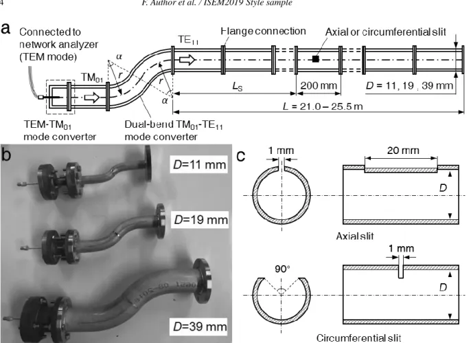
Figure 1 (a) illustrates the structure of the TE11 mode converter, comprising a TEM-TM01 mode
converter [11] and a dual-bend TM01-TE11 mode converter [12]. TE11 mode converters for inner pipe
diameters D =11, 19, and 39 mm were designed following a systematic method [10] proposed by the authors, and the procedure is briefly interpreted as follows: (1) Design a TEM-TM01 mode converter for
a certain D by changing the exposure length of a semi-rigid cable’s core wire lP using numerical
simulation, and determine the operational frequency range of TM01 mode; (2) Over the obtained
frequency range, compute the mode conversion when TM01 mode propagates through two inversely
connected bends (TM01-TE11 mode converter), based on the theory of mode coupling due to a bend [13];
(3) Alter the dimension of the bend (curvature radius r and bend angle α) to obtain an optimum conversion characteristic from TM01 to TE11 mode in the frequency domain. In this study, the curvature
radii and bend angles of two bends were set to identical for simplification. A detailed computational procedure and simulation model are given in the preceding study [10]. Table 1 summarizes the optimized values of lP, r, and α for three TE11 mode converters, and their working frequency spans fW were obtained
accordingly, over which the energy ratio of TE11 mode was greater than or equal to 90%.
Fig. 1. Structure of the TE11 mode converter.
Comparisons between theoretical and numerical results of the optimized fractional energy are displayed in Fig. 2 (a), (b), and (c), for the three TE11 mode converters. Good consistency is observed for each
scenario, and the working bandwidths of the three mode converters were 7.0, 4.0, and 1.9 GHz. It can be seen that the working bandwidth of the TE11 mode converter decreases when D becomes larger, which is
not preferable because the time domain resolutionis inversely proportional to the frequency bandwidth [14]. However, this problem can be resolved in the future by applying an optimized design of the TEM-TM01 mode converter [11] to widen the operational frequency range of the TM01 mode, or by selecting
different r and α for the two bends of the TM01-TE11 mode converter to improve the conversion efficiency
F. Author et al. / ISEM2019 Style sample 3
Fig. 2. Conversion characteristics of the three TE11 mode
converters, (a) D =11 mm, (b) D =19 mm, (c) D =39 mm.
3. Experiment
3.1. Experimental setup
Figure 3 (a) shows the experimental system. A network analyzer (Agilent Technologies, E8363B) was employed to generate TEM mode microwaves, which propagated through a flexible cable (Junkosha. Inc., MWX051) and were converted into circular TM01 mode by the TEM-TM01 mode converter. The
converted TM01 mode microwaves were subsequently converted into TE11 mode by the TM01-TE11 mode
converter and entered the pipes under test. The three TE11 mode converters were fabricated based on the
results given in Table 1 and portrayed in Fig. 3 (b).
Brass pipes of the same three inner diameters and lengths over 20 m were prepared for the experiment, by connecting several short pipes (1.0, 1.5 or 2.0 m in length each) with flange pipe fittings. An axial or a circumferential slit was machined in the middle of a short pipe (200 mm in length, D =11, 19, and 39 mm) to simulate a crack, and their dimensions are displayed in Fig. 3 (c). Moreover, to each D, another short pipe of the same length but with no fabricated slit was used for reference. The short pipes were longitudinallysituated at different positions (LS) along the pipes under test. According to the analysis in
our previous study, the sensitive areas of linearly-polarized TE11 mode microwaves against slits in a
circumferential direction are dependent on the polarization (horizontal or vertical), whereas an orthogonal deployment of the TE11 mode converter can eliminate the dead detection zones of each polarization and
thus implement a thorough inspection of the inner surface of the pipe. Therefore, in this experiment, reflection signals were measured only under a state of horizontal polarization, and the slits were deployed at the corresponding sensitive areas in the circumferential direction. Table 2 summarizes the experimental parameters. It should be noted that: due to the precision limit of the mechanical fabrication, the inner diameter of the TM01-TE11 mode converter for D =19 mm was actually 18.7 mm, and the 0.3 mm
difference in diameter between the mode converter and the pipe resulted in a 0.4 GHz frequency span shift, compared with the frequency span fW given in Table 1. The reflection signals were measured as
S-parameters in the frequency domain at 3201 evenly spaced sampling points, and were further processed using a dispersion-compensation method [15] to predicate the location of the flaw in a pipe.
Table 2 Experimental parameters
Parameter (unit)
Inner pipe diameter, D (mm)
11 19 39
Frequency span, f (GHz) 26 – 33 15.4 – 19.4 7.3 – 9.2 Pipe length, L (m) 21 22.5 25.5
Short pipe position, LS (m) 5, 10, 15, 20 4, 8, 12, 16, 20 4, 8, 12, 16, 21, 24
D (mm) r (mm) r/D (-) α (deg.) lP (mm) fW (GHz) 11 30 2.73 48 3 26–33 19 50 2.63 50 5 15–19 39 100 2.56 51 9 7.3–9.2 Table 1 Parameters of the three mode converters
4 F. Author et al. / ISEM2019 Style sample
Fig. 3. Experimental setup, (a) overview of the experimental system (not to scale), (b) three TE11 mode converters, (c)
dimensions of the axial and circumferential slits (D = 11, 19, and 39 mm, not to scale).
3.2. Results and discussions
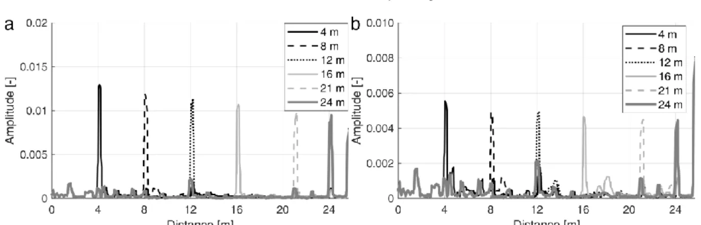
The experimental results for three different D values are depicted in Figures 4, 5, and 6. In the case D = 39 mm, shown in Fig. 4 (a) and (b), the clear reflection peaks appearing at LS = 4, 8, …, 24 m indicate
that both the axial and circumferential slits were detected at each location in the pipe. Small reflection peaks whose amplitudes were smaller than 0.002 were mainly due to the flange connections, while the reflection at 25.5 m corresponds to the pipe end. It should be noted that the results of D = 39 mm exhibit clear pulses even though the working bandwidth was not so wide. This implies that this method is prospectively applicable to the inspections of pipes of larger diameters, after further optimizing the designs of the TEM-TM01 and TM01-TE11 mode converters. Similarly, when D = 19 mm as shown in Fig.
5, explicit reflection signals can be observed where the axial and circumferential slits were deployed. When D = 11 mm, the sharp and steep reflection peaks shown in Fig. 6 (a) reveal that the axial slit can be detected with a high sensitivity. However, the result of the circumferential slit, shown in Fig. 6 (b), is more complicated: the reflection from the circumferential slit became smaller, meanwhile, some unknown reflections (highlighted with the dashed-line box) occurred at positions in which neither slit nor flange connections existed. After comparing the reflection signal of the circumferential slit with that obtained using the reference pipe (with no slit) shown in Fig. 6 (c), it can be seen that the reflections from the circumferential slits (highlighted with solid-line box) at LS = 5, 10 and 15 m are still discernible for
detection, while the unknown reflections may result from some hidden corrosion inside a 2 m long pipe. Moreover, it should be noted that: when the pipe diameter becomes smaller, the working bandwidth increases accordingly, while the reflection signal tends to decay faster because the sweeping frequency also increases.
Fig. 4. Processed reflection signals (D=39 mm) from two slits situated at LS= 4, 8, 12, 16, 21 and 24 m, (a) axial slit, (b)
circumferential slit.
Fig. 5. Processed reflection signals (D=19 mm) from two slits situated at LS= 4, 8, 12, 16 and 20 m, (a) axial slit, (b)
circumferential slit.
Fig. 6. Processed reflection signals (D = 11mm) from two slits situated at LS= 5, 10, 15 and 20 m, (a) axial slit, (b)
6 F. Author et al. / ISEM2019 Style sample
4. Conclusion
This study evaluated the effect of pipe inner diameter on the applicability of a technique using TE11
mode microwaves for crack detection. Three mode converters of three different inner diameters were designed using theoretical calculations and numerical simulations, and these two results accord well with each other. The experimental verification was carried out using pipes of the corresponding three inner diameters and two artificial slits (axial & circumferential), while the results showed that both two types of slits were detectable in each pipe, at a distance of 15–24 m. Furthermore, the influence of pipe diameter on the detection capability of this method was discussed to evaluate its viability for the inspection of larger or smaller diameter pipes.
Acknowledgments
This study was partially supported by Grant-in-Aid for JSPS fellows (No. 18J20649). The authors appreciate the assistance of the mechanical fabrication provided by Mr. Takao Nagaya, affiliated with the School of Engineering, Tohoku University. And we also would like to thank Dr. Helena Geirinhas Ramos and Dr. Artur Lopes Ribeiro from Universidade de Lisboa, for their insightful suggestions to our study. The first author is supported by the China Scholarship Council (CSC).
References
[1] Z. Chen, N. Yusa, K. Miya, Enhancements of eddy current testing techniques for quantitative nondestructive testing of key structural components of nuclear power plants, Nuclear Engineering and Design, 238.7 (2008), 1651-1656. [2] J.R. Lee, H. Jeong, C.C. Ciang, D.J. Yoon, SS. Lee, Application of ultrasonic wave propagation imaging method to
automatic damage visualization of nuclear power plant pipeline. Nuclear engineering and design, 240.10 (2010), 3513-3520.
[3] K. Sugawara, H. Hashizume, S. Kitajima, Development of NDT Method Using Electromagnetic Waves, JSAEM Studies in Applied Electromagnetics and Mechanics. 10 (2001) 313–316.
[4] T. Shibata, H. Hashizume, S. Kitajima, K. Ogura, Experimental study on NDT method using electromagnetic waves, Journal of Materials Processing Technology. 161 (2005) 348–352.
[5] L. Liu, Y. Ju, A high-efficiency nondestructive method for remote detection and quantitative evaluation of pipe wall thinning using microwaves, NDT&E International 44 (2011),106–110.
[6] K. Sasaki, T. Katagiri, N. Yusa, H. Hashizume, Demonstration of the Applicability of Nondestructive Microwave Testing to the Long-Range Inspection of Inner-Surface Cracks in Tubes, Materials Transactions 58 (2017) 692–696. [7] T. Katagiri, K. Sasaki, H. Song, N. Yusa, H. Hashizume, Proposal of a TEM to TE01 mode converter for a microwave
nondestructive inspection of axial flaws appearing on the inner surface of a pipe with an arbitrary diameter, International Journal of Applied Electromagnetics and Mechanics 59 (2018),1–8.
[8] R.E. Jones, F. Simonetti, M.J.S. Lowe, I.P. Bradley, Use of microwaves for the detection of water as a cause of corrosion under insulation, Journal of Nondestructive Evaluation 31 (2012) 65–76.
[9] K. Sasaki, T. Katagiri, N. Yusa, H. Hashizume, Experimental verification of long-range microwave pipe inspection using straight pipes with lengths of 19–26.5 m, NDT&E International 96 (2018), 47–57.
[10] G. Chen, T. Katagiri, H. Song, N. Yusa, H. Hashizume, Detection of cracks with arbitrary orientations in a metal pipe using linearly-polarized circular TE11 mode microwaves, NDT & E International 107, (2019), 102125. (https://doi.org/10.1016/j.ndteint.2019.102125.)
[11] K. Sasaki, L. Liu, N. Yusa, H. Hashizume, Optimized microwave excitation probe for general application in NDT of wall thinning in metal pipes of arbitrary diameter, NDT&E International 70 (2015), 53–59.
[12] S. Yang S, H. Li, Optimization of novel high-power millimeter-wave TM01-TE11 mode converters. IEEE transactions on microwave theory and techniques, 45.4(1997), 552-554.
[13] H. Li, M. Thumm, Mode conversion due to curvature in corrugated waveguides, International Journal of Electronics 71 (1991), 333–347.
[14] Gifuni A, Perna S. Analysis on the Calculation of the Inverse Discrete Fourier Transform (IDFT) of Passband Frequency Response Measurements in Terms of Lowpass Equivalent Response. Progress In Electromagnetics Research, (160) 2017, 63-69.
[15] Y. Sakai, N. Yusa, H. Hashizume, Nondestructive evaluation of wall thinning inside a pipe using the reflection of microwaves with the aid of signal processing, Nondestructive Testing and Evaluation 27 (2012), 171–184.
Electromagnetics and Mechanics 誌に投稿のため ISEM2019 事務局より)
--- Forwarded message --- From: <[email protected]>
Date: Thu, Mar 5, 2020 at 1:32 PM Subject: Manuscript 19-38 Decision To: <[email protected]>
Dear Dr. Chen:
Your manuscript (19-38) has been accepted in ISEM2019. A proof of your manuscript will arrive within the next weeks. Thank you for your excellent contribution, and we look forward to receiving further submissions from you in the future.
Sincerely, Jinhau QIU ISEM2019
To obtain reviews and confirm receipt of this message, please visit: https://msTracker.com/reviews.php?id=138440&aid=257241