平成 30 年度
若狭研究室 冬の研究会
【第 31 回】
2019 年 1 月 12 ~ 14 日
静岡県リゾーピア熱海
参加者 若狭研究室
坂口喜生 若狭雅信
(
教授)
森野勇 矢後友暁(
助教)
若狭研究室OB
・OG
石川慶(M2)
前山智明 長谷川貴一(M2)
高篠鮎人 土田暉(M2)
熊谷澪 西村晨平(M1)
高橋伶奈 若松郁佳(M1)
武田知也 篠原優太(B4)
水野智久 知々田優介(B4)
吉田朋美 細田敦也(B4)
発表プログラム
1.
単斜晶DPH
の磁場効果測定石川慶
2.
イオン液体中での光誘起電子移動反応に対する磁場効果の原因土田暉
3.9,10-
ジフェニルアントラセン単結晶中のT-T
消滅による傾向に対する磁場効果長谷川貴一
4.
イオン液体中でのベンゾフェノンの磁場効果西村晨平
5.
三重項増感反応による三重項ゲルミレンの発生に関する検討若松郁佳
6.
アントラセンでのトリプレットフュージョンの磁場効果篠原優太
7.
イオン液体中でのSF
効果知々田優介
8.
磁気同位体濃縮のためのラジカル対の寿命の測定細田敦也
9.Magnetic Field Effect in the Recombination of Short Lifetime Radical Pairs
矢後友暁
冬の研究会 2019.1.12-13
単斜晶
DPH
の磁場効果測定M2
石川 慶【Abstract】 Singlet fission (SF) is a process in which an excited singlet molecule (S1) and a ground singlet
molecule (S0) turn into two excited triplet molecules (T1). This reaction is studied actively now because SF generates two excitons from one photon and can improve solar energy generation efficiency. The mechanism of SF has not been known clearly yet. Thus, we studied the mechanism of SF by using magnetic field. Diphenylhexatriene (DPH) is known to be a SF material. In this work, we used super conducting magnet to study magnet field dependence of fluorescence from DPH crystal. We observed clear magnetic field effects (MFEs) on fluorescence intensity under the magnetic fields up to 10 T. We determined the structure of a reaction intermediate and electric interaction in singlet fission from MFE measurements.
【序論】 シングレットフィッション
(SF)
とは励起一重項分子が隣接した基底一重項分子にエネル ギーを分け与えて二つの励起三重項を生じる過程である。SF
を起こす物質を太陽電池素材として 用いることでエネルギー変換効率が向上すると示唆されたことにより、現在、SF物質を用いた太 陽電池開発が注目されている[1]
。しかし、SF
の機構や理論は未だ解明されておらず、太陽電池の 実用化にも至っていない。私たちはSF
物質の蛍光強度には磁場効果が発現するという点に着目し、SF
物質の蛍光強度の磁場効果を解析することでSF
の機構・理論解明を試みている。本報告では従来得られていた斜方晶
DPH
ではなく単斜晶DPH
を再結晶により得ることができ たため、単斜晶DPH
の磁場効果測定を行った。【実験】 蛍光測定には単斜晶
DPH
ジフェニルヘキサトリエン(DPH)
の結晶を用い、励起(LED
ランプ)を
365 nm
で行い,0~10 Tの磁場下で蛍光強度(観測波長:490 nm)を観測した。この際、分光器の前には観測波長のバンドパスフィルターを装着した。また、蛍光強度の角度依存性を測 るために、水平面内(磁場方向)で平板状の結晶を
0°
~360°
まで回転させた。【
X
線構造解析】 今回用いた試料は和光純薬で購入したDPH
を、アセトニトリルを溶媒として再 結晶して得られたものを用いた。この結晶の構造を特定するために、X 線構造解析を行った。そ の結果図1
のようにな構造であることが分かり、単斜晶であると特定することができた。Fig.1. (a)X
線構造解析に使用したDPH
単結晶(b)特定した結晶構造(単斜晶)
(a) (b)
【単斜晶
DPH
の磁場効果測定】 単斜晶DPH
の蛍光強度磁場効果を0°、 30°、 60°、 90°、 120°、 150°、
180°の位置で測った結果を図2に示す。縦軸の R(B)は B T
のときの蛍光強度を0 T
での蛍光強度で割ったものである。このグラフを見ると
1~10 T
にかけて、大きくR(B)
の増加がみられる。斜方 晶DPH
のときとは異なりdip
は観測されなかった[2]。これは、単斜晶DPH
内の三重項対に10 T
内にdip
が現れる交換相互作用(|J |<6.0 cm-1)を持つパターンが存在しないためであると考えられる。
また、各角度においての
R(B)
最大値を比較した角度依存性の図を図3
に示す。【低磁場領域での磁場効果】本報告では単斜晶
DPH
の低磁場領域での磁場効果の測定も行った ため、こちらについても報告する。結果は図4 のようになった。この結果と既報にある低磁場 領域での磁場効果を解析したものと比較すると、単斜晶
DPH
内ではヘリングボーン構造でのSF
が優勢であるのではないかと考えられる[3]。[1] Smith, M.; Michl, J. Chem. Rev. 2010, 110, 6891-6936.
[2] Yago, T.; Ishikawa, K.; Katoh, R.; Wakasa M. J. Phys. Chem. C. 2016, 120, 27858-27870.
[3] Wakasa, M; et al; Commun. Chem. 2018, 1, 9.
Fig.2.
単斜晶DPH
の磁場効果角度依存性
Fig.3.
各角度においてのR( B )最大値
角度依存性の図
Fig.4.
単斜晶DPH
の低磁場領域での磁場効果
冬の研究会
20190112
9,10-ジフェニルアントラセン単結晶中の T-T
消滅による蛍光に対する磁場効果M2
長谷川貴一【序論】
T-T
消滅過程では,励起三重項分子が隣接する励起三重項分子に対してエネルギーを 与え,一つの励起一重項分子を生成する.近年,有機デバイスの開発においてT-T
消滅 のような励起状態の融合過程やその逆過程の分裂過程が注目を集めている.しかし,こ れらの過程の機構は明らかになっていない.9,10-
ジフェニルアントラセン(DPA)(Fig.1)
はT-T
消滅を利用した波長変換1)によく用いられる発光分子である.本研究では,DPA
単結晶中のT-T
消滅過程の解明を目指して,S-T
励起後にT-T
消滅を介して生成される 励起一重項分子から発せられる蛍光の磁場効果を観測した.1971
年にMerrifield
らによ って同様の実験がなされたが,実験条件が不明であった2).さらに,レベルクロッシン グ機構による磁場効果(
蛍光強度の増加)
の角度依存性を測定,解析することで,T-T
消 滅過程の中間体である相関三重項対の構造解析を試みる.【実験】
蛍光測定にはトルエンで再結晶した
3mm
角程度の9,10-
ジフェニ ルアントラセン(DPA)
単結晶を用いた. 使用した励起光はHe-Ne
レ ーザー(632.8nm)
で,0~1.5T
の磁場領域で,S1←S0
励起で観測される 蛍光と同じ460nm
で発光を観測した. ただし,分光器を通すと光が 弱すぎて検出できないため,バンドフィルターを装着し,450-500nm
の光を観測した.また,蛍光強度の角度依存性を測定するために,DPA
単結晶を磁場方向の面上で0~360
°で回転させた.DPA
単結晶 の単結晶x
線構造解析を埼玉大学化学分析支援センターに依頼した.【結果】
0~1.5T
の磁場領域での蛍光強度の磁場効果を0°, 30°, 60°, 90°で測定したものを Fig.2
に示 す.R(B)は各磁場における蛍光強度を0T
の時の蛍 光強度で割った相対強度である.グラフより0.6T,
1.2T
を極大点にもつ蛍光強度の増加が観測された.実測の蛍光強度の増加の大きさ(Fig.3)と,生じた蛍 光強度の増加の大きさに角度依存性があるかどう
0.85
0.9 0.95 1 1.05 1.1 1.15
0 0.5 1 1.5
R(B)
B / T
0°
30°
60°
90°
Fig.1. DPA
Fig.2
各角度におけるDPA
の磁場効果かを確認するために行ったシミュレーション結果
(Fig.4),
単結晶X
線構造解析の結果(Fig.5)
を示す.各角度における実測の蛍光強度の増加の大きさ にシミュレーション結果をフィッティングした ところ,結果はよく一致しなかった.シミュレ ーション結果は
Fig.5
の着色した異なる配向の 三重項対がT-T
消滅過程の中間体であるときの ものである.詳細は当日議論する.1) Singh-Rachford, TN; Castellano, FN, Coord. Chem. Rev. 2010, 254, 2560.
2) Merrifield, R. E. Pure Appl. Chem. 1971, 27,481-498.
Fig.3.
実測の磁場効果の大きさの角度依存性
Fig.5.
単結晶X
線構造解析の結果0.06
0.07 0.08 0.09 0.1 0.11 0.12 0.13 0.14
0 60 120 180 240 300 360
磁場効果の大きさ
degrees / °
3J a&b 4J a&b 6J a&b
Fig.4.
計算の磁場効果の大きさの角度依存性
0.06
0.08 0.1 0.12 0.14 0.16 0.18 0.2
0 60 120 180 240 300 360
磁場効果の大きさ
degrees / °
0.6T実測値 1.2T実測値
2018.1.12~13
冬の研究会イオン液体中での光誘起電子移動反応に対する磁場効果の原因
修士
2
年 土田暉【序論】
イオン液体(ILs)とは常温で液体の塩である。初めて合成された
ILs
は空気中で不安定であったが[1]、1990年代初頭に空気や水に 安定なILs
が報告され研究が盛んになった[2]。ILsには不揮発性、不燃性、高粘度、極性部と非極性部が分離したナノスケールの秩 序構造をもつなど分子性溶媒と比べて特異な性質がある。
ラジカル対に磁場を印加すると、スピン変換速度が変化して散逸 ラジカルの収量に影響を及ぼす。この効果を磁場効果と呼び、その 大きさはラジカル対の周辺環境を反映する。例えば、ミセルのよう なかご効果や高粘度溶液によりラジカル対の散逸を抑制するもの で大きな磁場効果が観測される。
当研究室では、異なる粘度、カチオン構造の
ILs
を用いた中性 ラジカル対での磁場効果を観測しており、その原因をILs
のかご効果によるものであると結論づけている[3]。また、電荷を持ったラジカルイオン対を生じる
Benzophenone (BP)、1,4-Diazabicyclo[2.2.2]octane (DABCO)の ILs
溶液では、中性ラジカルと比べ 大きな磁場効果が観測されると報告されており[4]、その原因は溶液-溶媒クーロン相互作用によ るものとされている。そこで行われたのは短鎖カチオンILs
を用いたものだけであった。本研究 では、長鎖カチオンILs
が短鎖カチオンILs
と異なる磁場効果の観測が期待できることから、長 鎖カチオンILs
を用いて磁場効果実験を行った。そこで生じた磁場効果の原因を、粘度によるも の、もしくはミセルのようなドメイン構造を作ることによるものという2
つの観点で調査した。【実験】
イオン液体
DTMA TFSA
を合成し、ヘキサンと水で洗浄し、ディフュージョンポンプによる真 空乾燥を行った。BP 10 mM、DABCO 100 mMのDTMA TFSA
イオン液体溶液を調整し、過渡吸 収測定を行った。励起光にはNd:YAG
レーザーの第三高調波(355 nm)を使用し、検出光源にはXe
フラッシュランプを使用した。また、電磁石により磁場印加を行った。さらに、チラーでセ ル周囲に冷却または加熱した水を流し、温度(粘度)調節を行った。Fig. 1
使用したイオン液体、溶質。
【結果と考察】
Figure 2
に1 µs、1.7 T
のR(B)の粘度依存性を示し
た。グラフから、散逸ラジカルの相対収量(R(B) = Abs(BT) / Abs(0 T))は測定した粘度の範囲内において粘度に
大きく依存していることが読み取れる。異なるイオン液体 であっても、粘度が近い数値であればほぼ同様のR(B)
をとることがわかる。このことから、イオン液体中の光誘 起電子移動反応に対する磁場効果は、イオン液体のア ルキル鎖長にかかわらず粘度に比例して大きくなる。R(B)が粘度に比例することに関して、光誘起電子移
動反応の散逸生成物に関する量子収率[5]から考察し た。量子収率φは次の式で表される。Φ
=kesc / kesc + krec
ここで
kesc
はラジカルの散逸速度、krecは再結合速 度である。この式のkesc
には粘度が拡散係数として含まれ ており、粘度に関して式変形を行うと次のようになる。kesc = K / η
Φ
= (K / η) / (K / η) + krec1 / Φ
= 1 + (krec / K) ×η
… ①R (B)は 0 T
と磁場印加時の散逸生成物量の比であるため、
R(B)
=Φ
B T/ Φ
0 Tとなる。粘度を大きく変化させた時
0 T
の変化に比べ、磁場をかけた時の変化は非常に小さいため、
Φ
B Tを一 定であると考える。つまり、R(B)=(定数) ×1 / Φという 形になる。これと①より、R(B)は粘度に比例して大きくなっ ていると考えられる。【参考文献】
[1] P. Walden, Bull. Acad. Sci. St. Petersburg 1914, 405-422.
[2] T. Welton, Chem. Rev. 1999, 99, 2071−2083.
[3] T. Okada, T. Yago, T. Takamasu, and M. Wakasa, Phys. Chem. Chem. Phys., 2012, 14, 3490–3497 [4] T. Yago, Y. Ishii, M. Wakasa, J. Phys. Chem. C 2014, 118, 22356-22367.
[5]George. J. K,
小林宏(訳), 光電子移動, 丸善株式会社, 1997Fig. 3
散逸ラジカルの量子収率の逆数と粘度の関係。計算に使用した定数
K, krec
は適当な数値を使用している。Fig. 2
各イオン液体の1 µs
における1.7
T
のR(B)
粘度依存性。2019/01/12
冬の研究会イオン液体中でのベンゾフェノンの磁場効果
M1 西村 晨平
【序論】
イオン液体とは室温状態でイオンのみからなる極性溶媒であり、有機溶媒とは異なる 新たな溶媒として注目されている。そしてそれらの特徴として不揮発性、化学的安定 性などの物性が確認されている。イオン液体中では通常の溶媒とは異なる結果が報告 されており、これは粘度の違いだけでは説明できないため局所構造が原因であると考 えられている。しかし局所構造は明らかになっておらず、その解明の初歩としてベン ゾフェノンの水素引き抜き反応をナノ秒過度吸収測定法で磁場効果を利用して観察し た。
今回はイオン液体には N,N,N-Trimethyl-N-propyl-ammonium bis(trifluoromethanesulfonyl) amide (TMPA TFSA)を用いて測定した。
【実験】
今回は合成した TMPA Br とトリフルオロメタンスルホニルイミドをさらに混ぜ合わせ て反応させることでイオン液体として用いた TMPA TFSA を作った。
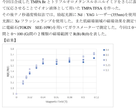
その後ナノ秒過度吸収法では、励起光源に Nd:YAG レーザー(355nm)を使用し、検出 光源に Xe フラッシュランプを使用した。また低磁場領域の磁場効果を測定するため に電磁石(TOKIN SEE-10W)を用いてガウスメーターで測定した。今回は 0~0.12 (T) 間と 0~100 (G)間の 2 種類の磁場範囲で R(B)/R(0)を表した。
【結果】
Fig1 0.4,0.5,1,1.25,1.5 (μs)における TMPA TFSA 中の BP ラジカルアニオンの収量比 磁場範囲は 0~0.12 (T)で測定を行った
収量比は 0.04 T で飽和している。0 T の時に比べて最終的には 1.6~1.7 倍に増加して
いる。
Fig.2 0.75,1,1.25,1.5 (μs)における TMPA TFSA 中の BP ラジカルアニオンの収量比 磁
場範囲は 0~100 (G)で測定を行った。
収量は約 20 G で 0.95 倍になり極小値を示した。それから 100 G まで徐々に増加して いる。
【考察】
Figure.1 の磁場効果は Hyperfine Coupling 機構 (HFC 機構)と緩和機構によるものと解釈 されている。TMPA TFSA 中でラジカルイオン対が TMPA TFSA 分子とクローン相互作 用したことで、ラジカルイオン対の散逸が抑制されたと先行実験で考えられてきた。
一方、Fig.2 では収量比が一時的に減少しており、その後は約 0.4 T まで増加してい る。これは hfc 機構と⊿g 機構による磁場効果と考えることができる。約 20 G までは 核スピンと電子スピンの超微細相互作用が外部磁場よりも大きいため T
0状態以外にも T
±1状態といった三重項状態間で hfc 機構が寄与し、三重項性の BP
*が減少するので BP ラジカルアニオンの収量比の減少として数値に出ていることが予測できる。約 20 G 以 上になると超微細相互作用よりも外部磁場が大きくなることで T
0状態とのスピン変換 の寄与がおおきくなるため三重項性の BP
*の収量が増加したと考えた。また⊿g 機構は T
0にしか寄与しておらず外部磁場が大きくなると⊿g 機構の寄与が大きくなったこと も、収量が増えた要因の一つである。しかし、この磁場効果は有機溶媒でも観察が可 能であるためイオン液体が及ぼす影響については考察できない。
【今後の課題】
実験を繰り返すことでエラーバーを出す
有機溶媒の磁場効果との比較からイオン液体が及ぼす 100 G 以下での磁場効果を検討
平成
30
年度 若狭研究室 冬の研究会三重項増感反応による三重項ゲルミレンの発生に関する検討
M1 若松
郁佳【序論】
14
族元素の一つであるゲルマニ ウムは、最も一般的な同族元素である炭 素と異なる化学的性質を持つことが知 られている。これらの低配位化合物は非 常に不安定で、例えばカルベンという2
価の炭素の化学種は非常に反応活性な ことで知られている。カルベンには一重 項と三重項の2
つの電子スピン状態が存在する。それぞれのスピン状態で反応挙動は異なり、今までも盛んに研究が行われてきた。
ゲルマニウム類縁体であるゲルミレンも同様で、これまで、直接的な光照射による一重項ゲ ルミレンの発生および反応性に関してはいくつか報告がされてきた。一方、光によるエネル ギー移動反応を介した三重項ゲルミレン発生の報告例は未だない。本研究では、出発物質と して
3,4-dimethyl-1,1-diphenyl-germacyclo-pent-3-ene(1)を用いた三重項増感反応により三重項
ゲルミレンを発生させ(Fig 1)、一重項ゲルミレンとの反応性の比較を行うことを目的として いる。これまで、既報にあるような無極性溶媒中での直接光励起による一重項ゲルミレン発生[1]
を再現した。また、増感剤としてチオキサントン(TX)を用いた無極性溶媒中での三重項増感 について実験を行い、三重項エネルギー移動と予想する反応が起こっていることを確認し た。今回、その生成物分析および
4-メトキシベンゾフェノン(4-MeOBP)、フェナントレン (phen)を用いた三重項増感について実験を行ったので、報告する。
【実験】①「1(10.6 mM) + TX(1.20 mM) + 2,3-ジメチル-1,3-ブタジエン(DMB) (103 mM)」「4-
MeOBP(10.5 mM)」
「1(10.8 mM) + 4-MeOBP(10.5 mM)」「phen(151 mM)」「1(10.8 mM) + phen(151mM)」それぞれのシクロヘキサン溶液を調製し、過渡吸収測定を行った。励起光には Nd:YAG
レーザー第
3
高調波、検出光にはキセノンフラッシュランプを用いた。②
1(10.3 mM ) + 4-MeOBP(10.8 mM) + MeOH(60.0 mM)
のシクロヘキサン溶液を調製し、定 常光照射実験を行った。光源にはキセノンアークランプ(USHIO, UXL-500D)を用い、1の直 接励起を防止するために、330 nm以下カットフィルターをはさんだ。30分照射後、試料をGC/MS
にかけて生成物分析を行った。【結果と考察】一重項ゲルミレンおよび三重項ゲルミレン発生において条件を揃えるため、
溶媒には直接光励起の場合と同様にシクロヘキサンを用いた。
?
1
Fig 1.三重項増感反応によるゲルミレンの発生
はじめに、TXを用いた三重項増感の生成物分析を行った。これまで、MeOHを用いた捕 捉実験を行ったが、捕捉生成物と予想するジフェニルゲルマンは観測されなかった。そこで 次に、1,3-ブタジエン類を用いた捕捉実験を行った。一重項ゲルミレンは
1,3-ブタジエンと
反応すると再び五員環のゲルマシクロペンテンに戻る[2]ことから、三重項ゲルミレンでも同 様の実験を行い、生成物の比較を行おうと考えた。しかし、捕捉剤としてDMB
を用いた過 渡吸収測定の結果、TXからDMB
への三重項エネルギー移動が優先的に起こってしまうた め、1,3-ブタジエン類は捕捉剤として適していないと判断した。結果、TX を用いた三重項 増感において、ゲルミレン捕捉生成物は観測されなかった。原因として、増感剤であるTX
の三重項エネルギーが低く、三重項エネルギー移動が効率よく行われなかった結果、発生し たゲルミレンが少なかったためと予想する。そこで、さらに高い三重項エネルギーを持つ4-
MeOBP
を新たな増感剤として用いて、三重項増感を試みた。4-MeOBP
のみでの過渡吸収測定を行った結果、3
4-MeOBP*は無極性溶媒とは反応しづらく、エネルギー移動が可能と言え
る。よって、1
を添加した場合での過渡吸収測定を行った結果、Fig 2
のようなスペクトルが 得られた。4-MeOBPのT-T
吸収波長である530 nm
の減衰曲線を比較した結果(Fig 3)、1添 加により減衰速度が約2.5
倍増加した。また、550 nmの吸収が大きく下駄をはいたことか ら、何らかの反応が起こっている。そこで、捕捉剤としてMeOH
を添加した試料に定常光 を照射し、GC/MS で生成物分析を行ったが、捕捉生成物と予想するジフェニルゲルマンは 観測されなかった。原因として、1
と増感剤との反応により、三重項エネルギー移動ではな く、増感剤のケチルラジカル生成促進が起こったためと考える。この結果から、ケトン類は 増感剤として適していないと言える。そこで、ケトン類以外の新たな増感剤として
phen
を用いた三重項増感を試みた。詳細は 当日議論する。[1] William J. Leigh, Cameron R. Harrington and Ignacio Vargas-Baca, J. Am. Chem. Soc. 2004, 126, 16105-16116.
[2] Lawrence A. Huck and William J. Leigh, Organometallics 2009, 28, 6777–6788.
Fig 2.1 (10.8 mM) + 4-MeOBP(10.5 mM)の
シクロヘキサン溶液の過渡吸収スペクトルFig 3.530 nm
での減衰曲線2019.1.12,13
冬の研究会アントラセンでのトリプレットフュージョンの磁場効果
B4
篠原 優太序論
トリプレットフュージョン(TF)とは、二つの励起三重項状態の分子(T1
)から一つの励起一
重項状態の分子(S1)が生成する光化学過程である(Fig.1)。生成した励起一重項状態の分子が
基底状態(S0)に戻るときに発する蛍光強度は磁場を印加することで変化する。1967
年にMerrifield
らによってこの蛍光強度が低磁場で増加し、高磁場で減少することが観測された(1)。
本研究はトリプレットフュージョンの機構の解明を目指して いる。今回の測定ではトリプレットフュージョンが実際に起こ っているのか確認するため、アントラセンに赤色光を照射し、
0
~1.6 Tまでの磁場を掃引で印加して、蛍光強度の変化を測定し た。
実験
実験の試料は再結晶したアントラセン(Fig.2)を使用した。
励起光は、三重項状態へ直接励起させるため
He-Ne
レーザー(波長 632.8 nm)を照射した。電磁石で 0~1.6 T
の磁場を印加して、アントラセンに
He-Ne
レーザーを照射したときに発する蛍光強度の変化を測定した。測定の際、
He-Ne
レーザーの前にHe-Ne
レーザー用のバンドバスフ ィルターとY52
カラーフィルター、観測部の前にTHORLABS
製FESH500,FESH600
のフィルターをそれぞれ設置した。結果と考察
測定結果を
Fig.3
示す。Fig.3
の横軸は磁場強度を表し、縦軸は各磁場強度での蛍光強度を ゼロ磁場の時の蛍光強度で割った相対蛍光強度である。アントラセンに赤色光を照射した ときの蛍光の強度はFig.3
より約0.034 T
でゼロ磁場の時より約+1.4 %になり、その後、減 少する。蛍光強度は1.6 T
でゼロ磁場の時の約88 %になった。低磁場領域において蛍光強度
が増加するのは、TF の中間体である(T1T
1)のスピン状態のうち一重項の成分がゼロ磁場の
時より増加するためであると考えられ、逆に高磁場領域で蛍光強度の減少は(T1T
1)のスピン
状態が磁場の方向に量子化されて一重項の成分がゼロ磁場の時よりも少なくなるためだと 考えられる。また
Fig.3
の結果は過去のMerrifield
の測定(1)と比べると蛍光強度の増加と減少の度合いFig.1
トリプレットフュージョンの過程Fig.2
アントラセンの構造式が異なっていた。(最大の増加率が+5 %で減少がゼロ磁場の
80 %)これは磁場効果の異方性
が原因だと思われる。磁場がかかる方向が変わることによって(T1T
1)のエネルギーが変化し
て、三重項励起子同士の相互消滅速度が変化するため、蛍光強度の増減の度合いが異なると 考えられる(2)。今後の予定
今回の実験では
Fig.3
のような結果が得られたが、過去のMerrifield
の測定(1)とは異なっ ていた。そのため、今回使用した結晶を用いて、結晶に対して違う方向から磁場を当ててど のように変化するのか測定が必要である。さらに、より高磁場で測定するため、He-Neレーザーを
10 T SCM
に導入し、装置を組ん で10 T
までのTF
の測定を行いたいと思う。また、角度依存性の測定や発光強度を大きくするため、純度の高いアントラセンの単結晶 の作成を行いたいと思う。
参考文献
(1) R. C. Johnson, R. E. Merrifield, P. Avakian, R. B. Flippen. Phys. Rev. Lett. 19, 285 (1967) (2)
井早 康正 編, “励起三重項状態”, p177-185, 南江堂(1975)0.85 0.87 0.89 0.91 0.93 0.95 0.97 0.99 1.01 1.03
0 0.5 1 1.5
相対蛍光強度
[a. u .]
磁場
[T]
Fig.3
アントラセンに赤色光を照射した時に発する蛍光の磁場効果2019.1.13 冬の研究会
イオン液体中の SF 効果
B4知々田優介
【序論】
近年、ホスト媒体にイオン液体を使用する UC の系が論文などで示唆されていて、イオ ン液体は無視できるほど小さな蒸気圧と高い熱安定性を持つ反応場として利用するこ とができます。 ごくわずかな蒸気圧でサンプルを超高真空下で脱ガスすることができ ます。トリプレットクエンチャーとして働きサンプル分解を引き起こす酸素分子の効 率的な除去が可能です。
イオン液体作成の一連の手順の確認を兼ねてイオン液体の作成を行なった。その後イオン 液体中の DABCO とベンゾフェノンに磁場を印加しながら過渡吸収測定を行なった。手順は 以下の様に行なった。
30%トリメチルアミン(150g,0.76mol)水溶液と 1-ブロモプロパン(50g,0.41mol)とエタノール
を混ぜ合わせ40℃に加熱したまま、24
時間攪拌を行なった。その後溶媒を留去して得られ た(TMPABr)の白色固体が得られた。この白色固体をエタノールで再結晶した。ろ液からもう 一度再結晶を行なった。TMPABr(22g,0.12mol) を イ オ ン 交 換 水 (124.7ml) に 溶 か し た 溶 液 と リ チ ウ ム ビ ス イ ミ ド (33.9g)をイオン交換水(22.85ml)に溶かした溶液を混ぜ合わせ室温下で
24
時間撹拌した。撹拌を止めると二層に分離した。その後上層を除去して下層を水
30
回ヘキサンで30
回洗 浄した。その後水を除去してから真空下で約20
時間乾燥させた。この後試料をグローブボ ックス内で保存した。そしてグローブボックス内で過渡吸収セルにイオン液体と DABCO、ベ ンゾフェノンを封緘して、過渡吸収実験を行なった。【実験】
過渡吸収測定の結果は右の 様になった。それぞれの系列 はそれぞれの時間での結果 を表しており単位はμs。
横軸は磁場を表しており単 位は T である。
縦軸は、磁場を印加していな い時の過渡吸収の吸光度を 1とした時の相対的な吸光 度を表す値 R(b)である。グ
ラフから分かる様に低磁場下では相対的な吸光度を表す R(b)の値が飽和していく。
1 1.2 1.4 1.6 1.8
0 0.02 0.04 0.06 0.08 0.1 0.12
低磁場下でのR(b)
0.05 0.1 0.2 0.3 0.4 0.5 1 1.25 1.5
2019.1.13 冬の研究会
この吸光度はイオン液体の磁場効果を表しており、その特性はイオン液体の粘度に起因し ているものであると考えられる。高い粘度によって散逸したラジカルが散逸しきらずに再 結合している。
次にイオン液体を溶媒としてイオン液体中の DPH の過渡吸収測定を行なった。
【結果】
以下に DPH のイオン液体中での過渡吸収スペクトルの結果を示す。
【参考文献】
(1)Yoichi Murakami, Hitomi Kikuchi,and Akio Kawai.Kinetics of Photon Upconversion in Ioni Molecules.J.Phys.Chem.B2013,117,2487-2494
-0.5 0 0.5 1 1.5 2 2.5
530 550 570 590 610 630 650 670
DPH (0.3mmol)の過渡吸収スペクトル
10ns 20ns 30ns 40ns 50ns 70ns 90ns 100ns 150ns
0 0.05 0.1 0.15 0.2 0.25 0.3
600 650 700
Ab s.
波⻑
DPH(0.08mmol )ヘキサン溶液の過渡吸収スペクトル
20ns
30ns
40ns
50ns
60ns
70ns
80ns
90ns
2019
年冬の研究会磁気同位体濃縮のためのラジカル対の寿命の測定
B4
細田敦也【序論】一般的な同位体濃縮は質量差に基づく性質の差を利用するため
,
重原子では濃縮が 困難になる.
そこで核スピンの違い(
磁気同位体効果)
を用いた同位体濃縮法が研究されてき た.
その中で収量検出磁気共鳴(RYDMR)
の原理を応用した,
光反応で生じた三重項ラジカル 対に磁場とマイクロ波を用いてスピン変換速度を選択的に制御するという手法では,
片方の 同位体のみを準位選択的に制御できることが知られている(1)が,
反応最終生成物に対する同 位体濃縮は報告されていない.
本研究室では水野
,
岩見らにより本反応系(Fig.1)
での同位体濃縮の研究(2),(3)が行われて おり,
再結合生成物の単離と原理的に本 反応系により同位体濃縮が可能である ことが報告されているが,
実際に同位体 濃縮された生成物の単離には至ってい ない.
本反応系の磁気同位体濃縮のための課題の一つとし て
,
ラジカル対の寿命が挙げられている.
ラジカル対の寿命の測定を目的として
,
ベンゾフェノン(BP)
のBrij35,Tween20
の各ミセル溶液中での過渡 吸収測定を行ったので報告する.
【実験】
BP 5mM
の各ミセル溶液(Brij35 50mM,Tween20 50mM)
をフローさせながら磁場を印加し
,
過渡吸収測定を行った.
励起光にはNd-YAG
レーザーの第三高調波(355nm)
を使用し,
検出光源にはXe
フラッシュランプを使用した.
【結果と考察】
BP
のBriji35
ミセル溶液中で過渡吸収測定を行うと,530nm
に三重項BP,550nm
にベンゾフェノンケチルラジカルのピークが見られる(Fig.2,3).620
~700nm
での吸光度の減衰速度解析を行うと
,
これは単一成分でフィッティングができ,
三重項BP
のもの と帰属した.
この三重項BP
の減衰速度を用いてベンゾフェノンケチルラジカルの0T
と0.4T
における減衰速度を考察した.
詳細は当日議論する.
↑Fig.
1
本研究で用いる反応系【参考文献】
(1) Okazaki,M;Toriyama,K,J.Phys.Chem,99,489(1995) (2)
水野智久,
修士論文(2018)
(3)
岩見法之,
修士論文(2011)
←Fig.2,3
0T
及び0.4T
におけるBrij35
ミセル溶液中のBP
の過渡吸収 スペクトルMagnetic Field Effect in the Recombination of Short Lifetime Radical Pairs
Magnetic Field Effect in the Recombination of Short Lifetime Radical Pairs
T. Yago
1,a)and M. Wakasa
1Department of Chemistry, Graduate School of Science and Engineering, Saitama University, 255 Shimo-ohkubo, Sakura-ku, Saitama 338-8570 Japan
(Dated: 30 November 2018)
Using the density operator formalism, an analytical model is developed to study magnetic field effect (MFE) induced by the hyperfine interaction in the recombination of radical pairs. Analysis reveals that the MFE curve, which is product yields plotted against magnetic fields, is Lorentzian in long-lived radical pairs. In the radical pair in which the lifetime of radical pairs is shorter than the time for singlet-triplet interconversion, the shape of the MFE curve is affected by the radical pair lifetime and is deviated from the Lorentzian shape. B
1/2, which is the magnetic field at half saturation, is shifted to higher magnetic field when the lifetime of radical pairs becomes shorter.
PACS numbers: 82.50.Hp
Keywords: Magnetic field, Radical Pairs, Hyperfine coupling, Coherence
I. INTRODUCTION
It is well established that the recombination of radical pairs (RPs) can be influenced by magnetic fields.
1,2RPs take either of two spin states; singlet (S) or triplet (T). Magnetic fields can change the ratio between the singlet and triplet RPs. The spin state selective recombination of RPs realizes magnetic field effects (MFEs) on the rate and yield of chemical reac- tions. In organic materials, hyperfine interaction
3–5and spin relaxation
6,7play major role in the generation of MFEs. In the absence of the external magnetic field, S ↔ T interconversion in RPs is driven by hyperfine interaction and spin relaxation.
Application of a magnetic field lifts the degeneracy between S and T states and blocks a part of S ↔ T interconversion in RPs.
The MFE associated with hyperfine interaction and spin re- laxation has been characterized by the saturation value at high magnetic fields and the curvature of the MFE curve, which is relative product yields (R) plotted against magnetic fields (B),
R (B) = Φ (B) −Φ (0)
Φ (0) (1)
where Φ (B) and Φ (0) is a product yield at B T and 0 T, respec- tively. In photochemical reaction systems involving RPs, the curvature of the MFE curve is discussed with the magnetic field B
1/2at which the MFE takes half the saturation value.
The B
1/2value for the MFE induced by the hyperfine inter- action has been estimated from the following equation for the RP consisting radical 1 and 2,
8B
1/2= 2 B
21+ B
22B
1+ B
2(2)
where B
1and B
2are synthetic hyperfine coupling effective for S ↔ T interconversion in radical 1 and 2, respectively.
9In the case that the B
1/2value in an observed MFE curve is close to the calculated B
1/2value, the origin of the MFE is judged to
a)Electronic mail: [email protected]
be the hyperfine interaction. When the observed B
1/2value is larger than the calculated B
1/2value, magnetic field dependent spin relaxation is assumed to contribute to the observed MFE.
In organic semiconductor, an injected electron and hole can form a RP. Luminescence and current flowing circuit of- ten show the MFE associated with the recombination of RPs.
R(B) in organic semiconductor is also referred as to magneto- luminescence or magnetoresistance. MFE curves observed in organic semiconductors are analyzed with the empirical laws (Lorentzian type),
10R(B) ∝ B
2B
2+ B
20(3) and (non-Lorentzian type)
R(B) ∝ ( B
| B | + B
0)
2(4) where B
0is a fitting parameter. B
0is expected to be associated with the hyperfine interaction in RPs. It has been known that B
0depends on molecular system and the voltage applied to organic semiconductor to inject electrons and holes.
10Though MFE curves can be fitted with Eq. (3) or (4) in many organic semiconductors, the physical meaning of B
0is often unclear.
In the present study, an analytical model is developed to study the MFE in short lifetime RPs using the density opera- tor formalism. We focus on the S ↔ T conversion in RPs in- duced by the hyperfine interaction. Our analysis reveals that the lifetime of RPs strongly affects R(B) and B
1/2when the lifetime of RPs is comparable with or shorter than the time for the S ↔ T conversion induced by the hyperfine interaction.
II. HYPERFINE INDUCED COHERENT SPIN DYNAMICS IN RADICAL PAIRS
A. Radical pair model
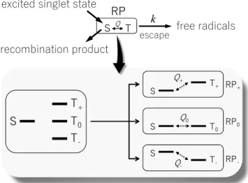
Figure 1 shows a RP model used in the present study. We
employ a photochemical reaction proceeded from an excited
Magnetic Field Effect in the Recombination of Short Lifetime Radical Pairs 2 singlet state. The RPs are born with the singlet state. A part
of the singlet RPs is converted to triplet RPs by the hyperfine interaction (Q). This process is influenced by the magnetic field. The radicals can escape from the singlet and triplet RPs with a rate constant k. In our model, escape rate k determines the lifetime of the RPs. The singlet RPs can recombine to give recombination products. We assume that the recombination reaction is much slower than the escape of radicals from the pair. The yield ( Φ (B)) of the recombination products is thus proportional to the yield ( Φ
S(B)) of the singlet RPs.
Φ (B) of the reocmbination product ∝ Φ
S(B) (5) We calculate Φ
S(B) from the time evolution of the S compo- nent in RPs to obtain the MFE on the recombination products.
The MFE on Φ
S(B) in the RPs is defined as,
R
S(B) = Φ
S(B) − Φ
S(0)
Φ
S(0) (6) To simplify the calculation procedure, we reduce the four- level spin system in the RP to a combination of two-level sys- tems. The RP is divided into the three RPs (RP
+, RP
0, and RP
−) as can be seen in Fig. 1. In RP
+, the S state is inter- acted with the T
+state whereas the S state has no interaction with the T
0and T
−state. In RP
0and RP
−, the S state is only interacted with the T
0or T
−state. We assumed that the S states in the three RP systems are populated equally at the initial state.
6 7
7
7
6 7 N
HVFDSH
IUHHUDGLFDOV 53
UHFRPELQDWLRQSURGXFW H[FLWHGVLQJOHWVWDWH
4
4 4
6 7
6 7
6 7
53
53
53 4
FIG. 1. A radical pair (RP) model used in the present study. The RPs are generated from the excited singlet state. The singlet RPs (S) can recombine and give the recombination products. The singlet RPs can be converted to the triplet RPs (T) by the hyperfine interaction (Q). The radicals escape from the pair with the rate constant of k, which determines the lifetime of the RPs. The RP spin system is divided into the three spin systems to reduce the four-level system into a combination of two-level systems.
B. The spin Hamiltonian
The spin Hamiltonian for the RP consisting of radical 1 and radical 2 and can be written as,
H = g µ
B(S
1· B + S
2· B) + a
1I
1· S
1(7) where S
1and S
2are the electron spin angular momentum op- erators for radical 1 and radical 2, respectively, B is the mag- netic field, a
1represents the hyperfine coupling constant for the nucleus on radical 1 and I
1represents the nuclear angular momentum operator for the nucleus on radical 1. Here only one nucleus is included in the spin Hamiltonian for simplicity.
We also assumed that the g-factors for radical 1 and 2 are the same. As was described in the previous section, the spin sys- tem in the RPs is reduced to S-T
+, S-T
0, and S-T
−systems to calculate the interconversion induced by the hyperfine inter- action. The spin Hamiltonian with the basis of the S and T
+states or the S and T
−states can be expressed as,
| S ⟩ | T
±⟩ H
±=
( 0 Q
±Q
±± g µ
BB
)
(8) where g µ
BB is the Zeeman interaction of the electron spin.
Here we omit the hyperfine coupling term in the diagonal el- ement for simplicity. Q
±is the mixing term for the two states and can be represented with a
1as follows,
Q
±= ∓ a
12 √ 2
√ I (I + 1) − m (m ∓ 1) (9)
where I and m are the spin quantum number and the magnetic quantum number for the nuclei, respectively. In the zero-field, the S and T
±states are degenerated and the Q term induces the S ↔ T
±conversion. In the presence of the magnetic field, the S and T
±states are energitically separated by the Zeeman interaction. Thus the S ↔ T
±conversion is not efficient in the presence of the magnetic field. This magnetic field dependent S ↔ T
±conversion is the source of the MFE.
The spin Hamiltonian in the basis of the S and T
0states can be expressed as,
| S ⟩ | T
0⟩ H
0=
( 0 Q
0Q
00
)
(10) where Q
0is the mixing term between S and T
0states and is represented as,
Q
0= m
2 a
1(11)
The rate the S ↔ T
0conversion is independent of the magnetic field.
C. Density operator formalism
Characterization of the coherent spin dynamics induced by
the hyperfine interaction is conveniently achieved using the
Magnetic Field Effect in the Recombination of Short Lifetime Radical Pairs 3 Liouville-von Neumann equation, which describes the time
evolution of the density matrix ρ (t) under the influence of the Hamiltonian H,
11i¯ h ∂ρ (t)
∂ t = [H, ρ (t)] (12) If H is a time-independent operator, Eq. (12) can be formally integrated to yield,
ρ (t) = exp( − itH/ h) ¯ · ρ (0) · exp(itH/ h) ¯ (13) where ρ (0) denotes the initial condition of the density matrix at time 0. In our reduced spin systems, ρ (0) is represented as,
| S ⟩ | T
n⟩ ρ
n(0) =
( 1/3 0
0 0
)
(14) where n specifies the triplet spin state (+, - or, 0) interacting with each S state. Knowledge of ρ (t) then allows calculations of the S components in the three RPs according to
ρ
SSn(t ) = trace[ ρ
n(t) · S
SS] (15) where S
SSrepresents the spin operator to extract the S compo- nents in the RPs.
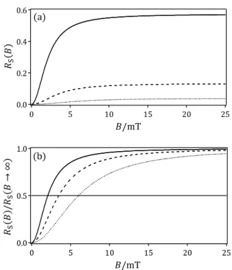
D. Time evolution of the singlet component
ͲǤ͵Ͳ
ͲǤʹͲ
ͲǤͳͲ
ͲǤͲͲ
ͷͲ ͶͲ
͵Ͳ ʹͲ
ͳͲ Ͳ
ߩ
ୗୗାݐ
ݐ Ȁ
FIG. 2. Time dependence of singlet components ( ρ
SS+(t) )
in singlet born RP
+calculated by Eq. (21) using the parameters of Q
+=1 mT and B=0 mT (solid line), B=1 mT (dashed line), and B=25 mT (dotted line), respectively.
The evaluation of ρ (t ) according to Eq. (13) requires diag- onalization of the spin Hamiltonian H. Below we consider the time evolution of the S component in RP
+in which the S state interacts with the T
+state. The matrix of Eq. (8) is readily diagonalized to yield the eigenvalues for S the and T
+basis
ε
S′= g µ
BB 2 − 1
2
√
(g µ
BB)
2+ 4Q
+2(16a) ε
T′+= g µ
BB
2 + 1 2
√
(g µ
BB)
2+4Q
+2(16b)
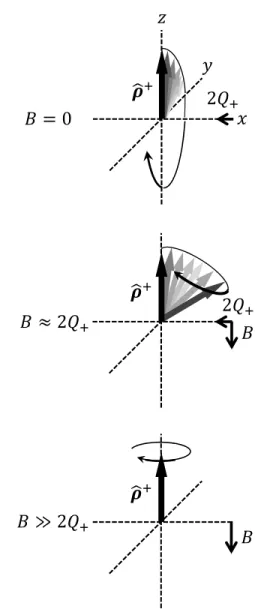
࣋
ෝ ା ݖ
ʹ ܳ ା
ܤ ൌ Ͳ
ʹ ܳ ା
ܤ
࣋
ෝ ା ܤ ൎ ʹ ܳ ା
ܤ
࣋ ෝ ା ܤ ب ʹ ܳ ା
ݔ ݕ
FIG. 3. Vector model for the magnetic field dependence of a singlet component in RP
+, starting from a pure singlet state. Rotation of the vector around the x axis is induced by the hyperfine interaction (2Q
+) while rotation about the z axis is caused by the external mag- netic field (B). The z component of ρ ˆ
+is the population difference ( ρ (t)
+SS− ρ (t)
+TT)
between the singlet and triplet in RP
+.
Using the substitution
tan 2 η = (2Q
+)/(g µ
BB) (17) One obtains the following eigenfunctions:
| S
′⟩ = cos η | S ⟩ + sin η | T
+⟩ (18a)
| T
′+⟩ = − sin η | S ⟩ + cos η | T
+⟩ (18b) In the eigenbasis of | S
′⟩ and | T
′+⟩ of the spin Hamiltonian H
+, the initial condition of the density matrix is given by,
| S
′⟩ | T
′+⟩ ρ
+(0) = 1
3
( cos
2η − sin η cos η
− sin η cos η sin
2η )
(19)
Magnetic Field Effect in the Recombination of Short Lifetime Radical Pairs 4 Similarly, S
SSin Eq. (15) can be represented as,
| S
′⟩ | T
′+⟩ S
SS= 1
3
( cos
2η − sin η cos η
− sin η cos η sin
2η )
(20) We now calculate the time evolution of the S component in the RPs according to Eq. (15).
ρ
SS+(t) = 1 3
{
1 − sin
22 η sin
2( 1
2 ∆ ε
′t /¯ h )}
(21) where
∆ ε
′= ε
T′+− ε
S′=
√
(g µ
BB)
2+4Q
+2(22) and η is defined in Eq. (17). Evidently, the S component os- cillates with respect to the time due to the coherent S-T
+con- version induced by the hyperfine interaction. Figure 2 shows time dependences of ρ
SS+(t) calculated with Eq. (21) using the parameter of Q
+=1 mT. The frequency and the amplitude of the oscillation depends on the hyperfine coupling constant and the magnetic field, causing the MFE. The oscillation ampli- tude decreases with the increase of the magnetic field whereas the oscillation frequency increases with the magnetic field in- creases. This frequency increase is a key to understand the MFE in short-lived RPs.
The magnetic field dependence of the ρ (t)
+oscillation can be rationalized with a vector model,
12which has been em- ployed to explain the generation of chemically induced elec- tron dynamic polarization (CIDEP) in RPs.
13Figure 3 illus- trates the vector model for spin dynamics in the S-T
+system.
In the vector model, spin states are defined with the quanti- zation axis of z, which also corresponds to the direction of the external magnetic field. The z component of the vector corresponds to the quantity of (
ρ (t)
+SS− ρ (t )
+TT) while the x and y components are associated with electron spin coherence and polarization. Details of the vector model are described in Appendix. In the initial state, the vector is aligned with the z axis on the upturn, representing a pure S state. In the ab- sence of the magnetic field, the vector rotates about the x axis by the hyperfine interaction with the frequency of 2Q
+. This rotation represents S ↔ T
+conversion and a part of the initial S state is converted to the T
+state. In the presence of the magnetic field whose magnitude is similar to 2Q
+, the vector rotates about the axis, which is a synthetic vector composed of the Zeeman and the hyperfine interaction. The amplitude of the (
ρ (t)
+SS− ρ (t)
+TT) oscillation is smaller than that in the absence of the magnetic field. However the frequency of the oscillation is increased because of the large magnetic interac- tion. In the presence of the large magnetic field, the ˆ ρ
+vector rotates about the z axis and the S ↔ T
+conversion is ineffi- cient.
A similar result is also obtained for RP
−. The S component also oscillates with time in RP
0. This oscillation is however independent of the magnetic field. These results are described in Appendix.
III. DISCUSSION A. Long-lived radical pairs
We first discuss the MFE in long-lived RPs. Because the S component in the RPs oscillates with respect to the delay time, we calculate Φ
S(B) by time averaging of the S component at the magnetic field of B. Time evolution of the S component is represented with a square of the sine function in each RP.
Time average of the square of the sine function is 0.5. Thus the time averaged S component in each RP is represented as,
ρ
SS+(t) = 1 3
{ (g µ
BB)
2+ 2Q
+2(g µ
BB)
2+ 4Q
+2}
(23a) ρ
SS0(t) = 1
6 (23b)
ρ
SS−(t) = 1 3
{ (g µ
BB)
2+ 2Q
−2(g µ
BB)
2+ 4Q
−2}
(23c) Φ
Sis the sum of the three time-averaged S components,
Φ
S= ρ
SS+(t) + ρ
SS0(t) + ρ
SS−(t) (24) At the zero-field, Φ
S=0.5 while the limit of B →∞ , Φ
S=5/6.
These values are one of the consequences of our model in which the four-level spin system is divided into the three two- level spin systems. R
S(B) is represented as,
R
S(B) = 1 3
{ (g µ
BB)
2(g µ
BB)
2+ 4Q
+2+ (g µ
BB)
2(g µ
BB)
2+ 4Q
−2} (25) R
S(B) is a sum of the two Lorentzian. When we assume Q
+= Q
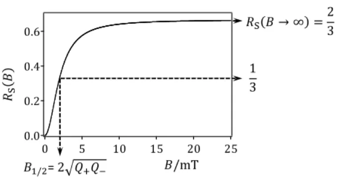
−, Eq. (25) is equivalent with Eq. (3). Thus Eq. (3) may be applied to the RP system where the lifetime of RPs is enough long compared with the period of the S ↔ T oscillation. From Eq. (25), one can readily obtain the B
1/2value as follows,
B
1/2= 2 √
Q
+Q
−(26)
Figure 4 displays an example of R
S(B) for long-lived RPs ac- cording to Eq. (25).
ͲǤ
ͲǤͶ
ͲǤʹ
ͲǤͲ
ʹͷ ʹͲ ͳͷ ͳͲ ͷ Ͳ