INVITED PAPER
Special Section on Recent Progress in Microwave and Millimeter-Wave Photonics TechnologyQuadrature-Phase-Shift-Keying Radio-over-Fiber Transmission for Coherent Optical and Radio Seamless Networks
Atsushi KANNO†a),Member, Pham TIEN DAT†,Nonmember, Toshiaki KURI†, Iwao HOSAKO††, Tetsuya KAWANISHI†,Members, Yoshihiro YASUMURA†††,Student Member, Yuki YOSHIDA†††,Member, andKen-ichi KITAYAMA†††,Fellow
SUMMARY We propose a coherent optical and radio seamless network concept that allows broadband access without deployment of additional op- tical fibers within an optical fiber dead zone while enhancing network re- silience to disasters. Recently developed radio-over-fiber (RoF) and digi- tal coherent detection technologies can seamlessly convert between optical and radio signals. A millimeter-wave radio with a capacity greater than 10 Gb/s and high-speed digital signal processing is feasible for this pur- pose. We provide a preliminary demonstration of a high-speed, W-band (75–110 GHz) radio that is seamlessly connected to an optical RoF trans- mitter using a highly accurate optical modulation technique to stabilize the center frequencies of radio signals. Using a W-band digital receiver with a sensitivity of−37 dBm, we successfully transmitted an 18.6 Gb/s quadrature-phase-shift-keying signal through both air and an optical fiber.
key words: radio over fiber, digital signal processing, coherent detection, millimeter-wave radio
1. Introduction
The construction of directly interconnecting optical and ra- dio networks has been of interest not only for enhancing network resilience but also because the implementation of such networks would help to foster more universal broad- band connectivity. Particularly where passive optical access networks are used in rural areas, the “last-mile” issue be- comes significant to broadband access if optical fibers can- not be deployed owing to geomorphic characteristics such as mountains, valleys, or rivers, or because the initial cost of installing fibers is too high. In such circumstances, high- speed radio connection is an attractive alternative candidate for extending the access area. Even where fixed wireless access solutions have already been installed, the conven- tional radio communication technology used may provide inadequate capacity to support future broadband services such as remote interactive healthcare using real-time, high- resolution video. Therefore, the enhancement of the net- work capacity and the support area of next-generation mo- bile backhauling networks will be necessary owing to the
Manuscript received June 11, 2012.
Manuscript revised September 28, 2012.
†The authors are with Photonic Network Research Institute, National Institute of Information and Communications Technol- ogy, Koganei-shi, 184-8795 Japan.
††The author is with Advanced ICT Research Institute, Na- tional Institute of Information and Communications Technology, Koganei-shi, 184-8795 Japan.
†††The authors are with the Graduate School of Engineering, Osaka University, Suita-shi, 565-0871 Japan.
a) E-mail: [email protected] DOI: 10.1587/transele.E96.C.156
rapid spread of high-speed mobile service. Because of its installation ease and universal broadband connectivity, the use of high-speed radio transmission seamlessly connected to optical fiber access networks represents a promising so- lution to such problems. Furthermore, this technology will likely play an important role in disaster recovery. Follow- ing the 2011 Japanese earthquake and tsunami, conventional networks broke down [1], [2]. In future situations involving the disruption of fiber cables, high-speed radio could be used to quickly restore networks by providing both protection and temporal links to stations.
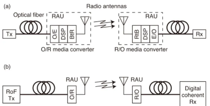
Millimeter-wave radio transmission is more attractive for high-speed radio rather than microwave transmission, as the achievable transmission capacity within the microwave frequency region is less than 5 Gb/s [3], [4]. In terms of atmospheric attenuation, the use of W-band (75–110 GHz) transmission appears to be suitable, as the attenuation within this band tends to be less than 1 dB/km [5]. Elec- tronic transceivers based on the recently developed high- speed, millimeter-wave integrated circuit (MMIC) technol- ogy represent one potential high-speed, high-frequency ra- dio transceiver solution; however, these have increased en- ergy consumption owing to their bandwidth and use of high frequencies. Furthermore, a function of the conver- sion between optical and radio signals, which involves not only modulation format conversion but also the addition of preambles in order to compensate for transmission im- pairments, is indispensable in a radio access unit (RAU) (Fig. 1(a)).
Fig. 1 Conceptual diagrams for (a) conventional optical-radio-optical transmission and (b) the proposed seamless conversion of radio and optical signal using an RoF transmitter and a digital coherent receiver. BtR and RtB indicate a baseband to radio signal converter and a radio to baseband signal converter, respectively.
Copyright c2013 The Institute of Electronics, Information and Communication Engineers
The radio-over-fiber (RoF) technology is a more promising solution for developing combined radio optical- fiber transmission networks. Using a photonic direct up- conversion technique, RoF can directly convert optical sig- nals to radio signals [6]. A high-speed photomixer in the RAU acts as an optical-to-radio (O/R) converter, seamlessly converting high-speed optical signals from RoF transmit- ters (Tx) directly into radio signals [7]–[10]. In a conven- tional conversion system (as shown in Fig. 1(a)), a digital signal processing (DSP) unit is usually installed in a radio- to-optical (R/O) converter to compensate for the degradation of air-transmitted signals as well as in the O/R converter to form the signal form for radio transmission. The use of such a unit may increase the energy consumption of both O/R and R/O converters. On the other hand, the use of optical dig- ital coherent detection techniques at the receiver (Rx) can completely compensate for transmission impairments such as media dispersion, eliminating the need to use DSP units altogether. As it is likely that an optical digital coherent Rx will soon be routinely implemented, the proposed method for seamless conversion between optical and radio signals is feasible for use in near-future optical networks (Fig. 1(b)).
In this study, we demonstrate high-symbol-rate RoF signal transmission, optically over fibers and via radio trans- mission through air. In this method, a quadrature-phase- shift-keying (QPSK) modulation at 10 Gbaud provides a data transmission capacity of nearly 20 Gb/s. In Sect. 2, the details of the proposed coherent optical and radio network concept are discussed and an energy consumption compari- son with a conventional scheme is made. Following this, the experimental setup is described in 3.1, and results, includ- ing discussion of how to extend the transmission distance and how to apply protection links, are presented in Sects. 3.2 and 3.3.
2. Coherent Optical and Radio Seamless Network Con- cept
Figure 2 shows a schematic drawing of a coherent opti- cal/radio seamless network composed of an RoF Tx, several RAUs, and a digital coherent Rx [10], [11]. During normal operation, called the “baseband operational mode,” the RoF Tx transmits a high-speed optical baseband signal to the Rx over an optical fiber (Fig. 2(a)). It is anticipated that the to- tal capacities of around 1 Tb/s or more will be needed in future metro area networks owing to the spread of 40/100 Gigabit Ethernet (GbE) implementation. In this situation, the RoF Tx might play a role as a conventional optical base- band transmitter, while the digital coherent Rx could be used to demodulate optical signals.
If the optical link between the Tx and the Rx is bro- ken through an optical fiber cut, the operational mode of the RoF Tx will change to the “RoF operation mode,” which is suitable for radio transmission (Fig. 2(b)). In the RoF oper- ation mode, the RoF Tx generates an RoF signal consisting of a baseband signal for data modulation and an optical lo- cal oscillator (LO) signal for direct photonic upconversion
Fig. 2 Conceptual schematics for (a) a typical optical fiber network case (i.e., “baseband operation mode”) and (b) a protection link mode (“RoF operation mode”) using high-speed radio at a fiber cut. Schematic spectra are also shown.
[6]. This generated RoF signal is then transmitted to the RAU, which consists of a simple O/R converter such as a photomixer. The RAU converts the received radio signal to an optical signal without changing the signal format, and the optical signal is then transmitted. Thus, this RAU repre- sents an alternative link that can act as the protection link for a cut optical fiber. The use of high-speed radio together with optical fiber transmission will generate protection links for enhancing network resilience. However, because of its wide transmission bandwidth, the total available capacity of an RoF link is not very large; thus, the use of millimeter-wave signals is required for high-capacity transmission.
For “last mile” situation including quick deployment of broadband connection such as a temporal link to tempo- ral stations at a disaster recovery and within an optical fiber dead zone, a radio Rx should be set at these stations with the “RoF operation mode” Tx. This radio Rx is comprised of the RAU and the optical Rx without an optical front end:
receiver antenna, a receiver front end including an analog- to-digital converter (ADC), and a DSP. Because the DSP configuration is a similar to the optical Rx, a number of com- ponents and resulting energy consumption would be reduced rather than that for the protection link. Especially in the op- tical dead zone, an optical fiber may be deployed in future due to the demand of higher capacity connection. To prepare for this, the feature of both the “baseband operation mode”
and the “RoF operation mode” should be implemented for the RoF Tx in advance.
The key feature of the proposed RoF transmitter is its use of frequency-locked, two-tone optical generation in or- der to stabilize the transmitted radio signals’ center frequen- cies within parameters allowed by radio regulations. An ad- vantage of this two-tone generation method, i.e., the “op- tical frequency quadrupler,” stems from its simple and ro- bust configuration, which is based on a single synthesizer, laser, and optical modulator and lacks movable structures [12]–[14]. The quadrupler forms optical two-tone signals
by means of separation of quadruple of the synthesizer’s in- cident frequencies. In testing, the phase noise of the gen- erated signal was observed to follow a theoretical degra- dation curve of 20 logm, wherem is the number of mul- tiplications [12], [15]. The optically synthesized frequency quadrupler is thus considered to be suitable both in terms of its frequency stabilization characteristics and its advanta- geous phase noise degradation curve.
3. Demonstration
To simply verify the proposed concept, a demonstration of combined multi-level and high-speed RoF signal generation, radio transmission, and reception in the W-band was con- ducted, as shown in Fig. 2(b). All the experiments described here were performed in a large-scale anechoic chamber.
3.1 Experimental Setup
Figure 3 shows the experimental setup of the proposed sys- tem [11]. An RoF signal was generated using an opti- cal two-tone generator with a separation of 92.5 GHz [14].
An arrayed waveguide grating (AWG) separated this signal into an upper-sideband (USB) signal for baseband modula- tion and a lower-sideband (LSB) signal for use as an opti- cal reference component that served as an optical LO. The data-modulated USB component signal was then reshaped by an optical bandpass filter (OBPF) with a bandwidth of 50 GHz to suppress unnecessary side lobe components. The LSB component was passed through a polarization con- troller (PC) to maximize parallel polarization relative to the USB. These two components were then re-coupled with an optical 3-dB coupler to form the desired RoF signal. This signal was directed into a 20-km-long standard single-mode fiber (SMF) for optical transmission. At the O/R conversion RAU, the transmitted signal was boosted by means of the EDFA, and the boosted RoF signal was then directed into an OBPF with a 1 nm bandwidth in order to suppress amplified
Fig. 3 Experimental setup for 10-Gbaud W-band QPSK RoF transmission.
spontaneous emission, after which the amplified RoF signal was converted from an optical to a radio signal by means of a uni-traveling carrier photodiode (UTC-PD). The radio sig- nal was amplified using an electrical power amplifier (PA) operating in the W-band and finally transmitted through air over a distance of between 5 and 10 m. The gain of the RAU and Rx antennas was 24 dBi.
The received signal was down-converted using a W- band double-balanced mixer (DBM) with a radio frequency bandwidth of 75–110 GHz, an LO of 75–110 GHz, and an intermediate frequency (IF) of DC–35 GHz. The DBM was connected to a free-running electrical LO operated at a fre- quency of 75 GHz. An electrical power of the LO was fixed about 10 dBm in all the experiments, that is no adaptive power optimization between the LO and the W-band sig- nals. The regenerated IF component was amplified using a pre-amplifier for optimization of the reception range of an ADC. The electrical signal was acquired by means of a real- time oscilloscope working as the ADC with a sampling rate and bandwidth of 80 GSa/s and 30 GHz, respectively. The resulting digitized signal was separated into its in-phase and quadrature (IQ) components by a digital signal processor, and these components were demodulated using phase noise suppression, frequency domain equalization, and symbol decision in a manner similar to the procedure used for off- line optical digital coherent detection. Figure 4 shows the optical spectrum at the input port of the UTC-PD, where a clear 92.5-GHz separation between the optical reference and the 10-Gbaud QPSK baseband components is observed. The small peak structure near the 1550.3 nm wavelength corre- sponds to a residual carrier component from the two-tone generator and the AWG. However, owing to its low peak power and frequency separation of 46.25 GHz from the de- sired optical signals, this component could not affect the converted radio signal and can be filtered out before radi- ating over the air by the bandwidth limitation of amplifier and antenna. It should be noted that these transmissions were performed under far-field transmission conditions; a Fraunhofer distance of 2D2/λ(whereDandλindicate the diameter of the antenna and the wavelength of the radio signal, respectively), which marks the traditional boundary value between near- and far-field, was approximately 0.5 m, which was much smaller than the transmission distances of
Fig. 4 Optical spectrum of the 10-Gbaud 92.5-GHz RoF signal transmitted into the RAU.
Fig. 5 Normalized FFT power spectra of received IF signals at the ADC (a) with a transmitter power amplifier and (b) without the amplifier (for reference).
5–10 m. All the experiments described here were performed in a large-scale anechoic chamber.
3.2 Results
Normalized power spectrum of the received radio signal at a transmitter power of 9 dBm, as estimated using a fast Fourier transform (FFT) of the time-domain signals ac- quired by the ADC, is shown in Fig. 5(a): this is just a periodigram, which is the modulus-squared of the discrete Fourier transform of the time series with the appropriate normalization. The main spectral lobe structure’s center at 17.5 GHz (which corresponds to a radio central frequency of 92.5 GHz at an LO frequency of 75 GHz) is clearly shown, along with some parasitic peaks. These may have been caused by the leakage of clock and LO signals to the ADC and to the receiver components, as no corresponding peaks can be seen in the optical spectrum (Fig. 4). For comparison, the spectrum obtained without the PA is shown in Fig. 5(b);
from this figure, it can be seen that the parasitic peak be- havior appears similar for both spectra. It can also be seen that the frequency response of the PA shows a slight relative power degradation at each IF frequency. It is further ap- parent that the power fluctuation of the PA spectrum shows an additional periodic modulation with a power of approx- imately 5 dB in the main lobe structure. This was possibly caused by interference between the UTC-PD and the PA, as these represented the only difference in the setup between the cases. It should be noted that the vertical axis in the fig- ure were normalized by the parasitic peaks around the center frequency to show the relative power spectra for comparison of the effect with the PA. The PA with a noise figure (NF)
Fig. 6 Constellation map of a received radio signal at a transmitter power of+9 dBm over 10-m transmission.
Fig. 7 Observed bit error rate dependence on transmitter radio power over 5-m (open circles) and 10-m (filled triangles) transmission.
larger than 8 dB and a gain flatness±5 dB around the full W- band could degrade a signal-to-noise ratio (SNR) rather than the signal without the PA, however, the transmitter power about 10 dBm can extend the transmission distance. This issue would be mitigated by the development and improve- ment of the low-NF PA.
Figure 6 shows the observed constellation map of the received radio signal at a transmitter power of approxi- mately 9 dBm. An estimated error vector magnitude (EVM) is about 23%, which corresponds to −12.8 dB. The clear separation and lack of IQ imbalance seem to indicate an error-free transmission. Degradation of the SNR could broaden the symbol mappings in the constellation map. The degradation could be caused by the W-band PA with the large NF and a poor frequency response described above. In addition, nonlinear response of the optical modulator might cause the degradation of an error vector magnitude. This issue can be solved by optimization of the operation condi- tion because a full-swing voltage operation in transmission function of the modulator suppresses optical output signal fluctuation.
The observed bit error rates (BERs) associated with transmissions of 5 and 10 m between the RAU and the Rx are shown in Fig. 7. An observed BER will depend on the transmitter power as measured at the output port of the UTC-PD. Theoretically, the estimated EVM for the
BER of 1×10⁻⁴ is about−11.5 dB, which corresponds to the SNR of 14 dB under the white Gaussian noise assump- tion. [16]. The observed penalty between this value and the obtained EVM of −12.7 is about 1.3 dB. The degra- dation could be caused by the PA described above. Over both transmission distances, the obtained BERs were within a forward error correction (FEC) limit of 2×10⁻³. In- stead of not employing the FEC on the transmission pay- load in these experiments, we try to estimate the net data rate if a practical FEC code would be deployed [17].
In this scenario, we assumed combined Reed-Solomon (RS) and Boss-Chaudhuri-Hocquenghem (BCH) super FEC codes standardized in ITU-T G.975.1 sub-clause I.4 [18].
An RS(1023,1007)/BCH(2047,1952) requiring an overhead about 7% corrects a 2.23×10⁻³ BER before the FEC to a 1×10⁻¹³BER after the FEC with a coding gain of 8.3 dB.
Thus, an 18.6 Gb/s radio transmission with a 7% FEC over- head was successfully performed.
There was a measured power penalty between the two distances of approximately 6 dB, caused by the free-space propagation loss. Using the Friis transmission equation Pr/Pt =GrGt(λ/4πR)2 (where Pr,Pt,Gr,Gt, andRindi- cate the power delivered to a transmitter antenna, the power available at the receiver, the transmitter and receiver antenna gains, and the transmission distance, respectively), an esti- mated difference of propagation losses of 6 dB is obtained at an antenna gain of 24 dBi, which agrees well with the ob- served penalty. This agreement confirms that transmission occurred under far-field conditions. Although attenuation caused by atmospheric oxygen is important, it has a value of approximately 1 dB/km; thus, in this experiment, the total atmospheric attenuation should have been less than 0.1 dB.
3.3 Discussion
The reduction in energy consumption of the proposed RAU based on its utilization of RoF Tx is of interest, since RAUs with low energy consumption should be in high demand in the future. However, there are currently no commercially available media converters for optical and radio conversions within the W-band. Therefore, the energy consumption of the 60-GHz band radio media converters must be approx- imated. Some reports have indicated that the energy con- sumption of a radio transmitter and receiver together would be less than or around 300 mW at a total output power of approximately 1 mW [19], [20]. On the basis of this result, the total converter energy consumption can be estimated to be a several Watts as shown in Fig. 1(a). On the other hand, the energy consumption of a UTC-PD used for O/R conver- sion is approximately 10 mW at an output radio power of about 1 mW [21]. As the DSP unit used at the Rx in the proposed system is the same as that used in a conventional optical link, the total energy consumption will be decreased by using an RoF Tx with a digital coherent Rx.
The interchangeability of the DSP unit with respect to optical and radio signal reception is another important is- sue. In a typical optical coherent receiver, the DSP unit
carries out the functions of carrier frequency offset (CFO) compensation, transmission dispersion compensation, and symbol deciding using a phase noise suppression feature.
From the viewpoint of the radio Rx DSP unit, dispersion compensation and symbol decision blocks should be imple- mented, given that radio signals transmitted over the opti- cal fiber experience a degree of degradation from fiber dis- persion. Using direct photonic upconversion of frequency- stabilized RoF signals, however, a radio carrier frequency can be stabilized, allowing for the exclusion of CFO at the optical coherent receiver’s DSP unit [14]. Thus, the CFO can be excluded from the DSP of the optical coherent re- ceiver. In this manner, additional reduction in DSP energy consumption might be attained.
Receiver sensitivity is a key concern in evaluating the potential to extend the transmission distance. Using the transmission equation, the estimated receiver power is ap- proximately −37 dBm with a BER of 10−3 which corre- sponds to a transmitter power of 6.93 dBm at a transmission distance of 10 m. Therefore, high power amplification at the RAU and use of a high-gain antenna are strongly indicated in order to significantly extend the transmission distance. A Cassegrain-type antenna with a gain greater than 50 dBi is commercially available [22]. In addition, a high-power, W- band amplifier with an output power of 5 W has been report- edly developed [23], [24]. Finally, the use of MMIC devices such as an integrated power amplifier has facilitated trans- mission distances of several kilometers for a 120-GHz on- off-keying radio with a data rate of 10 Gb/s [25]. It therefore seems likely that the antenna and amplifier requirements re- lated to the extension of the transmission distance will be solvable. The amplifier component described above can be used in conjunction with the RAU proposed here. Based on a transmitter power of 10 dBm, an antenna gain of 50 dBi, and the receiver sensitivity observed here, as well as ac- counting for atmospheric attenuation, an estimated trans- mission distance of approximately 3.8 km with a BER of 10−3 is obtained. It should be noted that this receiver sen- sitivity at the Rx is estimated in the absence of a W-band low-noise amplifier. Given that a typical low-noise W-band amplifier has a gain of 20 dB, the use of these would in- crease the sensitivity by 10–20 dB. Furthermore, applying an IQ mixer to the Rx can drastically reduce common-mode noises while increasing the sensitivity. Thus, enhancement of receiver functionality will also extend the transmission distance.
4. Conclusion
In this paper, we proposed a coherent optical and radio seamless network concept based on an RoF transmission system and digital coherent detection technologies. The proposed RoF Tx enables the generation of dual-purpose signals with stabilized central frequencies for conventional optical and radio transmission. The use of a DSP unit at the Rx, instead of at the RAUs, would help to compensate for transmission impairments, thus reducing the total energy
consumption of the system. To demonstrate the concept, 18.6 Gb/s W-band radio transmission following 20-km op- tical fiber transmission was successfully performed using a receiver sensitivity of−37 dBm. Extension of the transmis- sion distance by several kilometers can be achieved by us- ing a high-gain antenna such as a Cassegrain-type antenna and a high-power amplifier at the RAU in conjunction with a low-noise amplifier at the Rx. Such a transmission ex- tension would be sufficient to implement the “last mile” of a broadband access network using radio transmission and would additionally serve as a protection link for critical dis- aster recovery.
Acknowledgments
The authors would like to thank Dr. Katsumi Fujii and Dr. Toshihide Tosaka of the Applied Electromagnetic Re- search Institute at the National Institute of Information and Communications Technology, Japan, for their aid in us- ing a large-scale anechoic chamber. T. Kuri also wishes thank Dr. T. Miyazaki for his encouragement. Y. Yasumura, Y. Yoshida, and K. Kitayama would like to thank for the fi- nancial support by the NICT program “Agile deployment capability of highly resilient optical and radio seamless communication systems.”
References
[1] I. Sugino, “Disaster recovery and the R&D policy in Japan’s telecommunication,” Opt. Fiber Conf., Plenary Talk, Los Angeles, USA, 2012.
[2] “The NTT Group’s response to the Great East Japan Earth- quake,” NTT Group CSR Report 2011, pp.5–12, Dec. 2011.
http://www.ntt.co.jp/csr e/2011report/
[3] IEEE802 LAN/WAN Standards Committee, http://www.ieee802.
org/
[4] ITU-R WP5D. http://www.itu.int/ITU-R/
[5] Rec. ITU-R P.676-5, “Attenuation of atmospheric gases,” 2001.
[6] T. Kuri, Y. Omiya, T. Kawanishi, S. Hara, and K. Kitayama, “Optical transmitter and receiver of 24-GHz ultra-wideband signal by direct photonic conversion techniques,” IEEE Intl. Topic. Meeting Microw.
Photon. (MWP2006), W3-3, Grenoble, France, Oct. 2006.
[7] M. Weiss, A. St¨ohr, F. Lecoche, and B. Charbonnier, “27 Gbit/s pho- tonic wireless 60 GHz transmission system using 16-QAM OFDM,”
IEEE Intl. Topic. Meeting Microw. Photon. (MWP2009), Valencia, Spain, postdeadline, Oct. 2009.
[8] X. Pang, A. Caballero, A. Dogadaev, V. Arlunno, R. Borkowski, J.S.
Pedersen, L. Deng, F. Karinou, F. Roubeau, D. Zibar, X. Yu, and I.T. Monroy, “100 Gbit/s hybrid optical fiber-wireless llink in the W- band (75–110 GHz),” Opt. Express, vol.19, pp.24994–24949, 2011.
[9] A. Kanno, K. Inagaki, I. Morohashi, T. Sakamoto, T. Kuri, I.
Hosako, T. Kawanishi, Y. Yoshida, and K. Kitayama, “20-Gb/s QPSK W-band (75–110 GHz) wireless link in free space using radio- over-fiber technique,” IEICE Electronics Express, vol.8, pp.612–
617, 2011.
[10] A. Kanno, K. Inagaki, I. Morohashi, T. Sakamoto, T. Kuri, I.
Hosako, T. Kawanishi, Y. Yoshida, and K. Kitayama, “40 Gb/s W- band (75–110 GHz) 16-QAM radio-over-fiber signal generation and its wireless transmission,” Opt. Express, vol.19, pp.B56–B63, 2011.
[11] A. Kanno, T. Kuri, I. Hosako, T. Kawanishi, Y. Yoshida, Y.
Yasumura, and K. Kitayama, “High-speed fiber-optic and wire- less transmission with RoF and digital coherent communication
technologies,” Asia-Pacific Microw. Photon. Conf., Th.B-3, Kyoto, Japan, 2012.
[12] H. Kiuchi, T. Kawanishi, M. Yamada, T. Sakamoto, M. Tsuchiya, J.
Amagai, and M. Izutsu, “High extinction ratio Mach-Zehnder mod- ulator applied to highly stable optical signal generator,” Trans. Mi- crow. Theory Tech., vol.55, 1964–1972, 2007.
[13] T. Kawanishi, T. Sakamoto, and M. Izutsu, “High-speed control of lightwave amplitude, phase, and frequency by use of electrooptic effect,” J. Sel. Top. Quantum Electron., vol.13, pp.79–91, 2007.
[14] A. Kanno, K. Inagaki, I. Morohashi, T. Kuri, I. Hosako, and T.
Kawanishi, “Frequency-stabilized W-band two-tone optical signal generation for high-speed RoF and radio transmission,” Proc. IEEE Photon. Conf. (IPC11), TuJ4, Arlington, USA, Oct. 2011.
[15] R. Yamanaka, T. Fujita, H. Sotobayashi, A. Kanno, and T.
Kawanishi, “Analysis of phase noise of frequency quadrupler using dual-drive Mach-Zehnder modulator and two free running lasers,”
Asia-Pacific Microw. Photon. Conf., PA-6, Kyoto, Japan, 2012.
[16] R.A. Shafik, S. Rahman, and AHM Razibul Islam, “On the extended relationships among EVM, BER and SNR as performance metrics,”
Proc. Intl. Conf. Electric. Comp. Engineering, pp.408–411, 2006.
[17] G. Charlet, P. Tran, H. Mardoyan, M. Lefranc¸ois, T. Fauconnier, F. Jorge, and S. Bigo, “151×43 Gb/s transmission over 4,080 km based on return-to-zero differential quadrature phase-shift keying,”
31st Euro. Conf. Optic. Commun, Th 4.1.3, Glasgow, UK, 2005.
[18] Rec. ITU-T G.975.1, “Forward Error Correction for High Bit Rate DWDM Submarine Systems,” Feb. 2004.
[19] D. Dawn, P. Sen, S. Sarkar, B. Perumana, S. Pinel, and J. Laskar,
“60-GHz integrated transmitter development in 90-nm CMOS,”
IEEE Trans. Microw. Theroy Tech., vol.57, no.10, pp.2354–2367, 2009.
[20] K. Okada, K. Kondou, M. Miyahara, M. Shinagawa, H. Asada, R. Minami, T. Yamaguchi, A. Musa, Y. Tsukui, Y. Asaura, S.
Tamonoki, H. Yamagishi, Y. Hino, T. Sato, H. Sakaguchi, N.
Shimasaki, T. Ito, Y. Takeuchi, N. Li, Q. Nu, R. Murakami, K.
Bunsen, K. Matushita, M. Noda, and A. Matsuzawa, “A full 4- channel 6.3 Gb/s 60 GHz direct-conversion transceiver with low- power analog and digital baseband circuitry,” Tech. Dig. IEEE Intl.
Solid-State Circuits Conf., pp.218–219, 2012.
[21] H. Ito, T. Furuta, T. Ito, Y. Muramoto, K. Tsuzuki, K. Yoshino, and T. Ishibashi, “W-band uni-travelling-carrier photodiode module for high-power photonic millimetre-wave generation,” Electron. Lett., vol.38, pp.1376–1377, 2002.
[22] A. Kanno, P.T. Dat, T. Kuri, I. Hosako, T. Kawanishi, Y. Yoshida, Y. Yasumura, and K. Kitayama, “20-Gbaud QPSK optical and radio transmission using high-gain antennas for resilient access networks,”
IEEE Summer Topicals, WB1.3, Seattle, USA, 2012.
[23] M. Micovic, A. Kurdoghlian, H.P. Moyer, P. Hashimoto, M. Hu, M. Antcliffe, P.J. Willadsen, W.S. Wong, R. Bowen, I. Milosavlje- vic, Y. Yoon, A. Schmitz, M. Wetzel, C. McGuire, B. Hughes, and D.H. Chow, “GaN MMIC PAs for E-band (71 GHz–95 GHz) radio,”
Proc. IEEE Compound Semiconductor Integrated Circuits Symp., A.3, Monterey, USA, 2008.
[24] J. Schellenberg, E. Watkins, M. Micovic, B. Kim, and K. Han, “W- band, 5 W solid-state power amplifier/combiner,” Tech. Dig. IEEE Intl. Microw. Symp. (IMS 2010), pp.240–243, 2010.
[25] A. Hirata, R. Yamaguchi, T. Kosugi, H. Takahashi, K. Murata, T.
Nagatsuma, N. Kukutsu, Y. Kado, L. Iai, S. Okabe, S. Kimura, H. Ikegawa, H. Nishikawa, T. Nakayama, and T. Inada, “10-Gbit/s wireless link using InP HEMT MMICs for generating 120-GHz- band millimeter-wave signal,” IEEE Trans. Microw. Theory Tech., vol.57, no.5, pp.1102–1109, 2009.
Atsushi Kanno received B.S., M.S., and Ph.D. degree in science from the University of Tsukuba, Japan, in 1999, 2001, and 2005, re- spectively. In 2005, he was with the Venture Business Laboratory of the Institute of Science and Engineering, University of Tsukuba, where he was engaged in research on electron spin dy- namics in semiconductor quantum dot structures using the optical-polarization-sensitive Kerr ef- fect measurement technique. In 2006, he joined the National Institute of Information and Com- munications Technology Japan. From 2006 to 2007, he was also the mem- ber of the CREST-JST project “Creation of Novel Functional Devices Us- ing Nanoscale Spatial Structures of the Radiation Field.” He is working on microwave/millimeter-wave/terahertz photonics, ultrafast optical com- munication systems, lithium niobate optical modulators, and the study of ultrafast phenomena in semiconductor optical devices. He is a member of the Japan Society of Applied Physics (JSAP), and the Institute of Electrical and Electronic Engineers (IEEE).
Pham Tien Dat received the B.Eng. (Hons.) degree in electronics and telecommunication engineering from Posts and Telecommunica- tions Institute of Technology, Vietnam, in 2003, and the M.Sc. and Ph.D. degrees in science of global information and telecommunication stud- ies from Waseda University, Japan, in 2008 and 2011, respectively. He worked as a Researcher at Research Institute of Posts and Telecommu- nications, Vietnam from 2003 to 2006. In 2011, he joined the National Institute of Information and Communications Technology, Japan. His research interests are in the field of microwave/millimeter-wave photonics, radio over fiber and opti- cal wireless systems. Dr. Pham is a member the Institute of Electrical and Electronic Engineers (IEEE).
Toshiaki Kuri received B.E., M.E., and Ph.D. degrees from Osaka University, Japan, in 1992, 1994, and 1996, respectively. In 1996, he joined Communications Research Laboratory (CRL), Ministry of Posts and Telecommunica- tions (currently National Institute of Informa- tion and Communications Technology [NICT]), Tokyo, Japan, and is mainly engaging in re- search on optical communication systems.
Iwao Hosako received the B.S., M.S., and Ph.D. degrees from the University of Tokyo, Japan, in 1988, 1990, and 1993, respectively.
After two years with NKK Corp’s ULSI Lab- oratory from 1993 to 1994, he joined Commu- nications Research Laboratory (former name of NICT). He is currently Associate Director Gen- eral of Advanced ICT Research Institute at the National Institute of Information and Commu- nications Technology (NICT), Tokyo. His re- search during 1995–1998 focused on cryogenic readout circuits with emphasis on ultralow 1/f-noise transistors for a far- infrared detector system. His research interests include nearly all aspects of terahertz-device technologies such as semiconductor emitters, detectors, and optical thin films. He is serving on several research committees for terahertz technologies.
Tetsuya Kawanishi received the B.E., M.E., and Ph.D. degrees in electronics from Kyoto University, Kyoto, Japan, in 1992, 1994, and 1997, respectively. From 1994 to 1995, he was with the Production Engineering Labora- tory, Matsushita Electric Industrial (Panasonic) Co., Ltd. In 1997, he was with Venture Business Laboratory of Kyoto University, where he was engaged in research on electromagnetic scatter- ing and on near-field optics. He joined the Com- munications Research Laboratory, Ministry of Posts and Telecommunications (now the National Institute of Information and Communications Technology), Koganei, Tokyo, in 1998. In 2004, he was a Visiting Scholar with the Department of Electrical and Computer En- gineering, University of California, San Diego. He is currently a Director with the Photonic Network Research Institute Lightwave Device Labora- tory, the National Institute of Information and Communications Technol- ogy, and is working on high-speed optical modulators and on RF photonics.
Dr. Kawanishi received the URSI Young Scientists Award in 1999.
Yoshihiro Yasumura received the B.E.
from Osaka University, Osaka, Japan, in 2011.
His research interest is a digital signal process- ing for high-speed optical digital coherent detec- tion together with an orthogonal frequency divi- sion multiplexing technique.
Yuki Yoshida eceived the B.E., M.Inf., and Ph.D. degrees from Kyoto University, Kyoto, Japan, 2004, 2006, and 2009, respectively.
Since 2009, he has been an assistant professor in the Department of Electrical, Electronic and In- formation Engineering, Graduate School of En- gineering, Osaka University. His research inter- ests include digital signal processing for com- munications systems.
Ken-ichi Kitayama received the M.E., and Dr. Eng. degrees in communication engi- neering from Osaka University, Osaka, Japan, in 1976 and 1981, respectively. In 1976, he joined the NTT Laboratory. In 1995, he joined the Communications Research Laboratory (cur- rently, NICT), Tokyo, Japan. Since 1999, he has been the Professor with the Department of Elec- trical, Electronic, and Information Engineering, Graduate School of Engineering, Osaka Univer- sity, Osaka, Japan. His research interests are in photonic label switchings, optical signal processings, next-generation OCDMA and OFDMA access systems, and radio-over-fiber communica- tions. He has published over 260 papers in refereed journals, written two book chapters, and translated one book. He holds more than 40 patents.
He currently serves on the Editorial Boards of the J. Lightwave Technol, J.
Optical Communications and Networking as an Associate Editor. He is the Fellow of IEEE.
![Figure 2 shows a schematic drawing of a coherent opti- opti-cal / radio seamless network composed of an RoF Tx, several RAUs, and a digital coherent Rx [10], [11]](https://thumb-ap.123doks.com/thumbv2/123deta/5626421.1500283/2.892.470.811.116.371/figure-schematic-drawing-coherent-seamless-network-composed-coherent.webp)
![Figure 3 shows the experimental setup of the proposed sys- sys-tem [11]. An RoF signal was generated using an opti-cal two-tone generator with a separation of 92.5 GHz [14].](https://thumb-ap.123doks.com/thumbv2/123deta/5626421.1500283/3.892.99.402.814.1081/figure-shows-experimental-proposed-signal-generated-generator-separation.webp)
