10
SETTING UP OF ACOUSTIC DATA COLLECTION SYSTEM
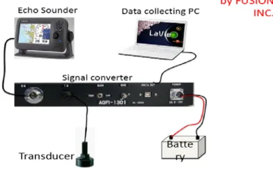
The acoustic data collection system hardware comprises of three main components such as Echo sounder (GP-1670F), Data Collection System (AQFI-1301), and Data Collecting Unit (PC). The set up of the actual acoustic data collection system hardware is shown in Figure 11.
Figure 11. Acoustic data collection system hardware connection layout.
Setting up the acoustic data collection system hardware could be carried out following the procedures below:
1. Power cable connection
Connect the power cable to the power connector of FURUNO GP-1670F and Echo Sounder Data Collection System (AQFI-1301). Connect the leads to the battery (12 or 24 VDC): red to plus (+) terminal and black to minus (-) terminal. Make sure that the shield is safe by connecting it to a ground which is the ship’s ground.
Note: Since the fuse (3A) is not waterproof, wrap the fuse holder with vinyl tape to keep water out from the fuse holder.
Figure 12. Power cable connection.
11 2. Transducer connection
Connect the transducer cable to the XDR port of GP-1670F and ES port of AQFI-1301.
Connect transducer cable, (520-5PSD) to TD port of AQFI-1301.
Figure 13. Transducer connection.
3. CAN bus (GPS Information) connection
Connect FURUNO CAN bus cable of NMEA Data Converter (IF-NMEA2K2) to CAN bus port of GP-1670F. Connect RS232 Serial port (9-pins) of NMEA Data Converter (IF-NMEA2K2) to USB-to-Serial (RS232) Converter. Connect USB of USB-to-Serial (RS232) Converter to computer.
Figure 14. CAN bus (GPS
Information) connection.
4. Data output connection
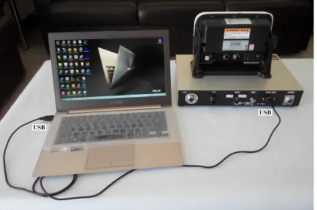
Connect data cable USB type B male to Data Out of Echo Sounder Data Collection System (AQFI-1301) and USB type male A to Computer USB port.
Figure 15. Data output connection.
12
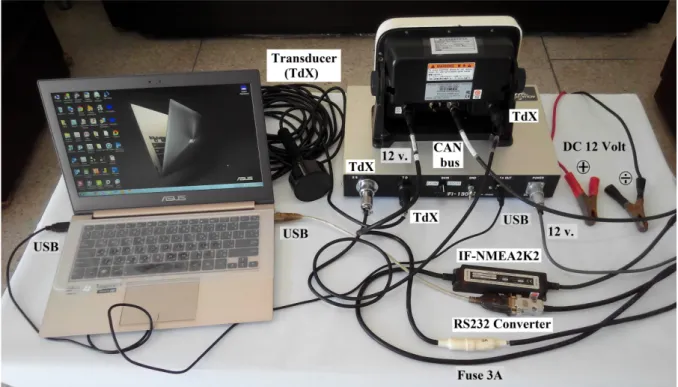
Figure 16. Echo sounder survey data collection system hardware connection.
Mount a Transducer
The thru-hull mount transducer provides the best performance of all, since the transducer protrudes from the hull and the effect of air bubbles and turbulence near the hull skin is reduced.
If the boat has a keel, the transducer should be at least 30 cm away from it.
The performance of fish finder is directly related to the mounting location of the transducer, especially for high-speed cruising. Thus, the installation should be planned in advance, keeping in mind the length of the transducer cable and the following factors:
• Air bubbles and turbulence caused by movement of the boat seriously degrade the sounding capability of the transducer. The transducer should, therefore, be located in a position where water flow is the smoothest. Noise from the propellers also adversely affects performance and the transducer should not be mounted nearby. The lifting strakes are notorious for creating acoustic noise, and these must be avoided by keeping the transducer inboard.
• The transducer must always remain submerged, even when the boat is rolling, pitching or planning (gliding) across water at high speed.
• A practical choice would be to place the transducer somewhere between 1/3 and ½ of the boat’s length from the stern. In the hull, it is generally practical to install or locate the transducer rather far from the boat stern, so that is always in water regardless of the planning attitude of the boat.