Title
Smart Acoustic Room (SAR) System and its Application
Author(s)
Asharif, Mohammad Reza; Chen, Rui
Citation
琉球大学工学部紀要(67): 15-20
Issue Date
2006-03
URL
http://hdl.handle.net/20.500.12000/1491
Bull. Faculty ofEngineering, Univ. ofthe Ryukyus No.67,200S
Smart Acoustic Room (SAR) System and its Application
Mohammad Reza Alsharif* Rui Chen*
'Department of Information Engineering, Faculty of Engineering, University of the Ryukyus, Okinawa, Japan
Emails: asharif@ie.u-rvukvu.ac.jp. kO38656@eve.u-mikyu.ac.jpAbstract
In this paper, the Smart Acoustic Room (SAR) system is presented for partitioning room acoustically. That is, in
different places of the room, one can hear to the desired signal. This is realized by robust estimation algorithm for well control of room acoustic impulse responses. Therefore, unwanted music or speech signal is canceled, while, at the same place, the desired signal (the desired music or speech) could be heard. And also, we apply the SAR system
into the double-talk echo canceling. The computer simulation results support the theoretical findings and verify the
robustness of the proposed algorithms.
Keywords: ANC, AEC, acoustic room impulse response, Smart Acoustic Room (SAR) system, Virtual
microphone, MSE
1. Introduction
Study of the room acoustic is an important topic in all
kinds of speech processing and audio systems. In hand free telephony or in teleconferencing system, acoustic echo canceller (AEC) [1] is used to remove the echo signal from speech. Here, echo is generated due to acoustic couplage between loudspeaker and microphone in a room. The echo degrades the intelligibility of the communication. Therefore, AEC tries to estimate the room acoustic response and make a
replica of the echo signal and remove it. Acoustic noise
control (ANC) [2] system is another example to reduce acoustic noise in a location of the room. Here, the acoustic noise is propagated through room acoustic and ANC tries to estimate this acoustic path to generate an opposite signal similar to noise and reduce it appropriately.
In all kinds of above-mentioned examples, we need to estimate and control the room acoustic response
between two locations. Nevertheless, this control could
be imposed electrically (AEC) or acoustically (ANC), the adaptive digital filter (ADF) is used to perform this job with an appropriate algorithm.
In this paper, we want to introduce a room with
smart acoustic (SAR). That is, the acoustic
response between two (or more) points could be
controlled smartly. By control, we mean to have a well estimation of the acoustic path between two points and then to make the appropriate signal to cancel an unwanted signal or to
emphasis to a desired signal (speech or music).
And also, we apply the SAR system into the double-talk echo canceling. That is, by smartly control the impulse response in the room the signals from the loudspeakers will be cancelled
at the microphone position. This is a new type of
echo canceling,
it is different with the
conventional echo cancellation, which cancels the echo signal in the telephone system electronically.
2. SAR System Model and its Application
Suppose that we want to listen to a Jazz music in one portion of a room and at the same time other fellow
wants to listen to a classic one in the other side of the
room. Also, we do not want to use headphone as it totally isolate the person from surrounding. Other
example is in a conference room or big hall, that we
have two kinds of audiences. In one section, audiences want to listen in Japanese while in other section international audiences are seated and they want to listen to the speech in English. Again we do not want to use headphone as here is very costly to manage the
system for each person and the Hall should be designed
for that or we need transceiver, which is also costly. But if we design the acoustic response such that Japanese loudspeakers cover the desired location while English loudspeakers cover the other part, just by seating in the right place one can hear to desired language. There are much more applications of SAR system. ANC is an especial case of SAR, because in a room we want to reduce the noise source propagation to a location. In more general case, we can define acoustic channels similar as radio or TV channels. Imagine you want to change the channel of TV by using a remote control. The same is possible to be performed for acoustic
channel. But, the difference here is location
dependency of the remote control. That is, depending on place of the remote control, one can push a bottom
to listen to a specific program that be propagated to that place only. If we move the remote control to other
location in the room, we can select another program
and set the acoustic path to listen only to specified
program. Therefore, in SAR we require to change and control acoustic impulse response of the room, as we : 2006 ¥ 1 £ 10 B
17 ¥ 11 M 23 0,
16 ALSHARIF • CHEN : Smart Acoustic Room (SAR) System and its Application
desire.
Of course, sound propagation through acoustic channel from one loudspeaker could cause perturbation for the
other one. This is because in contrast to
electromagnetic propagation and frequency division multiplexing (by using proper modulation technique) is not possible in acoustic wave propagation. Therefore,
by using a powerful algorithm in adaptive digital filter,
one can make the null point (zero point) of an acoustic
source to be set in specific location and/or move it to
any other location. 3. SAR Algorithm
In this paper, we challenge to control the acoustic response between two points as shown in Fig. 1. That is by using two speakers and one microphone to make an acoustic null point at the microphone position. In Fig.2, a SAR model by using the virtual microphone [3], [4], [5] is shown. The source signal x(n) is for instance a record player output or any audio electric signal. This signal usually converted to acoustic signal through an amplifier and a loudspeaker in order to propagate in a room for listening. The acoustic paths from Speaker Sj to the microphone M is wt(n) and the one from Speaker S2 is w2(n). We want to make a null point at the place of microphone M. For this purpose, we put one adaptive filter estimator h(n) in order to predict the acoustic paths and to zero-enforce the signal of M. The signal of
microphone is called the error signal, e(n), and it is
obtained as follows:
«) =x(n)*wl(n)+J<(n)*h(n)*w2(ri)
(1)
Flg.l. Two speakers SAR system
Aside of speakers SI and S2, we imagine that we have two virtual speakers SI and S2 in parallel with SI and S2, respectively. Also, we define two virtual acoustic
paths for Si and §2 as w\(n) and w2(n) from each virtual
speaker to a virtual microphone M_ (see Fig.2). The signal of the virtual microphone is e(n). According to Fig.2, we can write the following relation for the virtual
paths:
If h(n) is adapted perfectly, then the virtual error signal
will be diminished to zero. Therefore, in Z transform
we have:
X(z) * Wx (z) + X(z) * H(z) * W2 (z) = 0
That is:
(3)
From Eq. (1) and (3), we conclude that:
a(z)
(5)
W2(z) Wx{z) W2(z)
Function a(z) describes the relation between the real
and virtual part of the system. Then we can use two
simple LMS adaptive filters to estimate the impulse responses w; and w2. For estimation the wi, the error
signal can be written:
(6) W2(z)
As the same for estimation the w2., the error signal can
be written:
E.Jz)=-E(z)
(7)
SpukuS e(n) Sound source Afcpfot filter Kb)"UsJ'*1^^) *H
Sputa Sf -•'rr'l
■n r" VttuilMcMFig.2. SAR model by using the virtual microphone
That is, the acoustic paths wrfn) and w2(n) can be estimated by using the real error e(n). In order to reduce the computational complexity at this time all the
computation will be done in die frequency domain [6].
First, the FFT of the input signals x(n), y(n) are calculated.
N-\
k-(8)
where W shows complex exponential e Jl2"'N) ,Nis
the impulse response length.
Then, the FFT transform of the error signal is calculated
(10)
*=o
So, the acoustic impulse response can be estimated by
<■■»
The superscript * shows the Hermitian transposition and tr[] means the trace operator. Finally H(z) is calculated by Eq (4) and h(n) can be calculated by using the inverse FFT transform.
4. SAR Algorithm Based on Correlation Function In this section, the SAR algorithm based on the correlation function is presented [7]. The SAR system is shown in Fig.3. The aim of this system is that by control the acoustic impulse responses the signals in the room can be separated. The person can choose the desired signal just by seating at the different position. As shown as in Fig.3, the person who seating at the position A just can hear the desired signals from speakers S3 and SA , because the signals from speakers £, and S2 was cancelled. The same process will be done for the position B. The person who seating at the position B, just can hear the desired signal from the speakers Sl and S7.
v Speakersl
Room
B position \Signal from I
Sl. S2)
/
A position Signal from S3, S4 Speakers4Fig3 Four speakers SAR system
Because the processes for position A and B is same, at here just the process for the position A will be introduced. In the Fig.4, the structure of the proposed
SAR algorithm is shown. The desired signal from
speakers s3 and SA, are assumed as the double-talk signals. Also the proposed algorithm will be implement in the frequency domain.
For the double-talk condition the signal from the microphone will be defined as follows:
First the auto-correlation of the input signal is calculated:
x(j)x(j-k)
(14)
- k) (15) SpttkcrS. Sound sourceFlg.4 Structure ofthe SAR system based on correlation function And then the cross-correlation function is calculated:
J=°
R^ (n,k) =
2 d{j)y{.
/- k)
The fast Fourier transform is shown as below:
p<>Itj0.g
N-l N-l *=0 ntyU)y(J-k)
±JU)*U-k)
'±dU)yU-k)
y=ow»
w»
w»
w»
(17) (18) (19) (20) (21)So the acoustic paths can be updated by:
luFAn. p)F'(n,
p)=JV2(n,p)
F
2
The superscript * shows the Hermitian transposition
and trfj means the trace operator. Finally the h(n)
can be calculated by using the inverse FFT transform from the H(z).
18 ALSHARIF • CHEN : Smart Acoustic Room (SAR) System and its Application
5. Echo Canceller based on SAR System and Correlation Function
In this section, we combine ANC with AEC to improve echo canceller performance. In ANC, as we know the
acoustic noise is supposed to be cancelled by
generating an opposite phase signal that is generated by adaptive filtering of reference (main) noise signal. Now, if we use this ANC structure at near end room in AEC
system, then echo signal will be diminished at the microphone position. That is, a very week feed back
exists between loudspeaker and microphone. In a sense, we cancel echo signal before it enters to microphone, acoustically by using ANC system
In the Fig. 5, the proposed echo canceling system by using the smart acoustic room & correlation function is shown [8]. This algorithm uses two speakers and one microphone; by smartly control the acoustic impulse
responses the speaker signals will be cancelled at the
microphone position locally. That is, the microphone cannot receive any echo signal. For the double-talk, the correlation function in the frequency domain also is used.
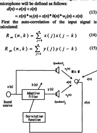
As shown as Fig. 5, x(n) is the input signal from the far-end room. y(n) is the output signal of the adaptive filter. e{n) is the signal from the speakers,
which is called as error signal. d{ri) is the signal picked up by the microphone, including the error signal
and double-talk signal. s{ri) is the double-talk signal from the near-end room.
For the double-talk condition the signal from the microphone will be defined as follows:
d(n)=e(n)+s(n)
= x(«)*w,(«) +x{n) *h(n)*w2(n)+s(n)
As same as the SAR system, which is presented in the previous section, if h(ri) is adapted perfectly, then the error signal e(n) will be diminished to zero. That is, the signal from speakers will be cancelled at the microphone position. The microphone cannot receive any echo signal.
First the auto-correlation of the input signal is calculated:
*„(»,*) = Z x{j)x{j-k)
(25)(26)
And then the cross-correlation function is calculated:
**(«,*) = Z d{j)x{j- k)
(27)
j=o
j- k) (28)
J=Q
The fast Fourier transform of the correlation functions are shown as below:
f-(».p) = Z [z *u)*u -*)V*
*=o|_y=o J(29)
N-X JV-1 tf-l *=0 7=0So the acoustic paths can be updated by:
(30) (31) (32) (33) (34) wi w2 speaker s2 y(n) correlation function adaptive filter x(n) speaker si near-end far-end
Fig.5 Echo canceling base on SAR system and correlation function 6. Simulation results
In this section first we explain the simulation results of the SAR system for partitioning room acoustically, then
we apply the SAR system into the double-talk echo canceling, of course the simulation results will be explained.
In simulation for SAR system, we assume that the person is seating at the position A. we want to cancel
the signals from speakers Sx and S2 • And the signal
from the speakers S3 and S4 will be heard as a desired signal. As shown as in Fig. 4, the signal x(n), y(n) are the input signals of speakers Sl and S2, respectively. The signal s(n) is the output signal from
speakers S3 and S4. At here, the signal s(n) is
assumed as the double-talk signal. The microphone M is set at the position A to pick up the error signal. The
input signal x(n) is a speech signal of woman in English and the double-talk signal s(n) is a speech of
woman in Japanese as shown in Fig. 6-a and 6-b, respectively. The adaptive filter has 32 taps. The step size is 0.01.
The acoustic paths wj (n) and w2 (n) of the room are assumed to have exponential decaying shape that decreases to -60dB after M sample, which are defined as follows:
wu (i) = Rand [cxp( -8/IM )] (35)
where Randn is a normal distributed random number between +1,-1 with zero mean and unit variance, w, 2 are the impulse responses from the speakers Sx and S2 to microphone, respectively.
In Fig. 6-c, the waveform of the error signal at the microphone position is shown. The signals are canceled
at the microphone position locally. In Fig. 6-d, the waveform of the signal, that is, what can be heard by
the person at position A, is shown. Compared with the
waveforms of the double-talk signal and the signal can be heard position A, which are shown in the Fig. 6-b
and 6-d, we can see that there are not much differences
between of the two waveforms. That is, the person who is seating at the position A, can just hear the signals
from the speakers s3 and SA, clearly.
(a) Input sigsnl x<n) (b) Double-talk signal s(n)
mi
fill -
i In
HI1
illik
P
2 3
Iteration (n)
(c) Error sijenl e(n)
S
.10* Iteration (n) (d) The signal otn) .10*
Fig. 6. Waveform ofsignals
The simulation results of the double-talk echo canceling based on the SAR system and correlation function is shown in Fig.7. As same as previous simulation, the input signal x(n) is a speech signal of woman in English and the double-talk signal s(n) is a speech of woman in Japanese as shown in Fig. 7-a and 7-b, respectively. The adaptive filter has 32 taps. The step size is 0.01.
12 3 4 5
Iteration (n) „ ^ q4
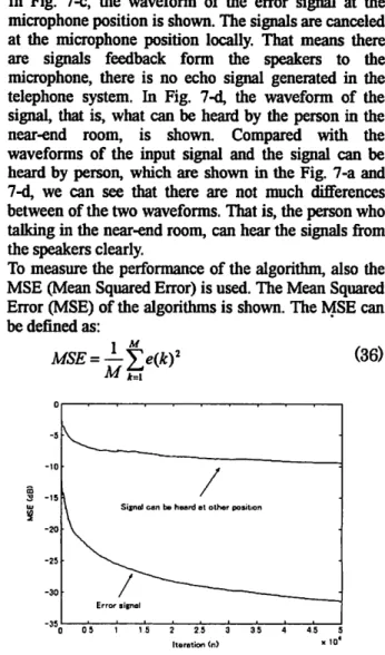
In Fig. 7-c, the waveform of the error signal at the microphone position is shown. The signals are canceled at the microphone position locally. That means there are signals feedback form the speakers to the microphone, there is no echo signal generated in the telephone system. In Fig. 7-d, the waveform of the signal, that is, what can be heard by the person in the near-end room, is shown. Compared with the waveforms of the input signal and the signal can be heard by person, which are shown in the Fig. 7-a and 7-d, we can see that there are not much differences between of the two wavefonns. That is, the person who talking in the near-end room, can hear the signals from the speakers clearly.
To measure the performance of the algorithm, also the MSE (Mean Squared Error) is used. The Mean Squared Error (MSE) of the algorithms is shown. The MSE can be defined as:
1 M
(36)
45
Fig.7 Waveform of signals
0 0 5 1 15 2 2 5 3 3 5
Iteration <n) x '°
FIg.8 The MSE ofthe proposed algorithm in double-talk condition. In the double-talk condition, the proposed algorithm converges to -32 dB of echo cancellation at the microphone and -8db signal can be heard, which is shown in Fig. 8. That is, the echo can be cancelled in microphone position by using the smart acoustic control & correlation function. And also the person who is talking in the near-end room can hear the signal from the speakers clearly.
7. Conclusion
In this paper, the SAR system and a new type echo canceling are presented. First the application of the Smart Acoustic Room system is introduced. Then we present a simple SAR system by using virtual microphone, the aim of this system is to make a null point at the microphone position locally. That means by control the impulse responses we cannot hear anything at the microphone position. The simple SAR system just can be implemented under a simple single-talk condition, it cannot work under a double-talk condition. As a solution, the SAR algorithm based on correlation function is presented for partitioning room acoustically. By smartly control the impulse responses, the signals in the room can be separated. The person can choose the
20 ALSHARIF • CHEN : Smart Acoustic Room (SAR) System and its Application
desired signal just by seating at the different position. Finally we apply the SAR system base on correlation function algorithm into the double-talk echo cancellation. This is a new type echo canceling, it is different with the conventional echo cancellation, which cancels the echo signal in the telephone system
electronically.
The simulation results show that the SAR system by using the virtual microphone can work under the single-talk condition very well, the SAR system based on the correlation function makes the signal separation in the room to become true. The double-talk echo canceling base on SAR system and correlation function has a satisfied convergence rate and speed. And also because this algorithm is implemented in the frequency-domain, the computational complexity is low, it makes the hardware implementation of this algorithm a realistic matter using a fewer chips of DSP, it requires
less LSI area. References
[1] S. Haykin, "Adaptive Filter Theory", Third Edition Prentice, Hall,
1996.
[2] S. M. Kuo, Dennis R. Morgan, "Active Noise Control Systems",
John Wiley & Sons, Inc, 1996.
[3] Y. Ohana, T. Kohna, "Direct Fully Adaptive Active Noise Control Algorithms Without Identification of Secondary Path Dynamics", IEEE International Conference on Control Application, Scotland,
2002.
[4] M. R. Alsharif, R. Higa, R. Chen, "Smart acoustic room", The 2004 autumn meeting of the acoustical society of Japan, pp601-602,
September 2004.
[5] M. R. Alsharif, R. Chen, R. Higa, "Smart Acoustic Room (SAR) System by Using Virtual Microphone", International Symposium on Telecommunications (1ST) 2003, Shiraz, Iran, 2005.
[6] M. R. Alsharif, F. Amano, "Acoustic echo-canceler using the FBAF algorithm," IEEE Trans. Communications, vol42, No. 12,
pp3090-3094, Dec. 1994.
[7] R. Chen, M. R. Alsharif, K. Yamashita, "Smart Acoustic Room (SAR) System", Symposium on Information Theory and its Applications (SITA) conference, pp.913-916, Nov.20-23, 2005, Okinawa, Japan.
[8] R. Chen, M. R. Alsharif,, K. Yamashita, "A New Type Echo Canceling by Using the Smart Acoustic Room (SAR) system & Correlation Function For the Double-Talk Condition", IEEE, EURASIP, 9th International Workshop on Acoustic Echo and Noise Control (IWAENC 2005), pp.29-32, Eindhoven, The Netherlands.