TiO
2
/Si composites synthesized by sol-gel method and
their improved electrode performance as Li-ion battery
anodes
Hiroyuki Usui1,2, Kuniaki Wasada1, Masahiro Shimizu1,2, and Hiroki Sakaguchi1,2,*
1Department of Chemistry and Biotechnology, Graduate School of Engineering, Tottori University
4-101 Minami, Koyama-cho, Tottori 680-8552, Japan
2Center for Research on Green Sustainable Chemistry, Tottori University 4-101 Minami,
Koyama-cho, Tottori 680-8552, Japan
*Corresponding author. Tel./Fax: +81-857-31-5265; e-mail: [email protected]
Keywords: TiO2/Si composite; Li-ion battery anode; Sol-gel method; Gas-deposition; Li-ion
diffusion
Abstract
Composites of rutile-type TiO2 and Si were synthesized by a facile sol-gel method for a
high-performance anode of Li-ion battery. We have investigated anode performance of binder-free thick-film electrodes prepared by a gas-deposition method using the TiO2/Si composites obtained.
The composite electrode exhibited a remarkably improved cyclability and a good high-rate performance: a discharge capacity at the 900th cycle was 710 mA h g–1, and a specific capacity per Si weight was as large as 1870 mA h g(Si)–1 even at a high current rate of 4.8C. It is suggested that a
electrodes. The results offer a utility of rutile TiO2 as a Li-ion conductor in Si-based electrodes for
1. Introduction
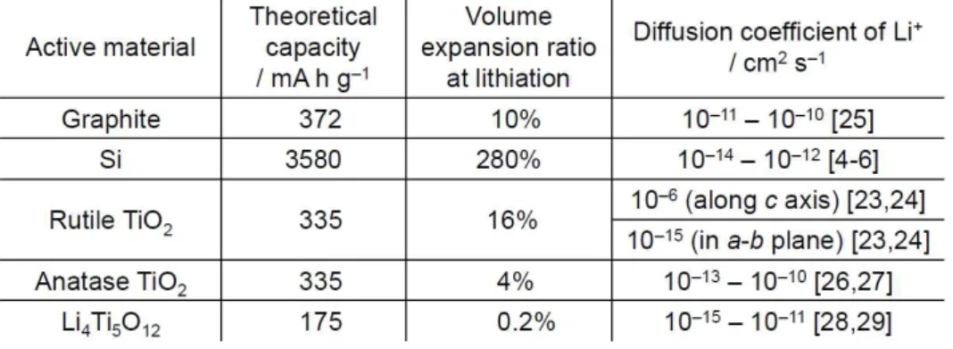
Li-ion battery has been utilized in various portable electronic devices for many years. The battery has a much higher energy density compared with other rechargeable batteries so far, but its performance still lies behind the demands in new applications for electric vehicles and stationary batteries. New electrode materials with high specific capacities are necessary to meet these demands. Silicon offers a huge theoretical capacity of 3580 mA h g−1 by the formation of Li15Si4 phase [1-3],
which is ten times larger than that of graphite in the anode of practically used batteries. A practical application of Si has been, however, hindered by a critical hurdle based on its crucial disadvantages as anode material. Silicon has a low diffusion coefficient of Li+ in it (D
Li+, 10–14–10–12 cm2 s–1 [4-6]),
and a low electronic conductivity. In addition to these, Si undergoes a significant volume expansion up to 280% (difference between original Si and Li15Si4) upon complete lithiation, which results in
generation of stresses as high as 1–2 GPa [7]. The large stresses lead to a severe mechanical damage and a rapid capacity fading for Si electrodes. To overcome this problem, many researchers have investigated various composite electrodes consisted of pure Si and other active materials compensating for the silicon's disadvantages.
We have recently studied various anode materials of intermetallic compounds [8,9], Si-based composites [10-19], and pure Si [20-22]. As a result of these studies, we have revealed that the anode performance is remarkably improved for Si-based electrodes by certain properties of the materials combined with Si. The properties required for the materials can be mainly classified into four factors, as follows:
1. Mechanical softness to relax the stress from Si 2. High electronic conductivity
3. Moderate reactivity with Li+
As for the third factor, a too high reactivity (a large specific capacity) is unfavorable because the large capacity often accompanies significant volume changes of the active material during Li+-insertion/extraction, which leads to a breakup of an electrode and its poor cyclability. We
consider that further improvement in the performance needs not only the moderate reactivity but also fast Li+-diffusion in active material. In this study, we propose a new strategy to enhance the cycling
performance of Si-based electrodes by the fast Li-ion conduction.
Rutile-type TiO2 has a smaller volume expansion ratio of 16% and a moderate theoretical
capacity of 336 mA h g−1. This capacity is a comparable to that of graphite. In some polymorphs of TiO2, rutile-type structure shows a very interesting Li+ diffusion: its diffusion coefficient along the
c-direction is approximately 10–6 cm2 s–1, while it is only 10–15 cm2 s–1 in the ab-plane [23,24]. The diffusion coefficient is extremely higher than that in graphite [25], Si [4-6], anatase-type TiO2
[26,27], and Li4Ti5O12 [28,29] as shown in Table 1. However, three-dimensional Li+ diffusion is
kinetically restricted in micrometer-sized rutile TiO2 because of its highly anisotropic diffusion.
Therefore, we expected that rutile TiO2 nanoparticles with an enough small size are one of the most
appropriate materials combined with Si. Some researchers have recently studied electrodes of TiO2
obtained by a polyol process [23] and sol-gel methods [30-33]. In this study, we chose a sol-gel method because this method is very suitable for a large-scale production and for a structure control of products. To evaluate fundamental electrode reactions, we employed a gas-deposition method [9-22] to prepare binder-free electrodes of TiO2/Si composites, and investigated anode performance
of the composite electrodes obtained.
2. Experimental
A commercial Si powder (Wako Pure Chemical Industries, 99.9%) was received, and was put in a zirconia vessel together with 10-mm-diameter balls. The weight ratio of the balls to the Si powder was 15:1. The vessel used was sealed to keep an atmosphere of dry argon gas. A mechanical milling
was performed using a high-energy planetary ball mill (P-6, Fritsch) for 10 min with a rotation speed of 380 rpm at room temperature. The particle size of the milled Si powder was measured by using a laser diffraction particle size analyzer (SALD-2300, Shimadzu Co. Ltd.), and was ranged from 0.4
µm to 3 µm. We confirmed that the most typical size was 0.5 µm.
Active material powders of TiO2/Si composites were synthesized by the following sol-gel
process: 4 mL of hydrochloric acid (Wako Pure Chemical Industries, 35–37% assay) was diluted with 56 mL of deionized water in a round-bottle flask, and then 2 mL of titanium(IV) tetraisopropoxide (TTIP; Ti(OCH(CH3)2)4, Wako Pure Chemical Industries, 95%) was dripped into
the solution. After a vigorous stirring for one hour at 55oC under 1500 rpm, the mechanically-milled
Si powder was added to the suspension. The stirring was continued for more three hours to promote a hydrolysis reaction of TTIP on Si particle surface. The colloidal suspensions obtained were centrifuged and washed with deionized water for seven times. The washed precipitation was dried in vacuum at 85oC for 24 hours to form TiO
2/Si composite powder as a final product. For comparison, a
powder of TiO2 alone was also synthesized. The synthetic conditions were based on other reports
[34-36], and have been further optimized by our preliminary experiments (see supporting information, Fig.S1 and Fig.S2). All reagents were analytical grade and were used without further purification in the experiment. The crystal structure of the powders was confirmed by using X-ray diffraction (XRD, Ultima IV, Rigaku) to be identified as rutile-type TiO2 structure (Inorganic Crystal
Structure Database, ICSD No.00-021-1276) as shown in Fig. S1. The morphology of the powders was observed by a field emission scanning electron microscope (FE-SEM, JSM-6701F, JEOL Ltd.) equipped with an energy dispersive X-ray spectroscope (EDS, INCAPentaFET-x3, Oxford Instruments).
Thick-film electrodes of TiO2/Si composites were prepared by a gas-deposition (GD) method [9].
We have demonstrated that thick films (a typical thickness of 1–4 µm) consisting of various metal, alloy, and oxide powders can be easily formed by a single deposition without any binder in this
method [9-22]. In this study, we prepared thick-film electrodes consisting of only TiO2 and/or Si.
The GD was carried out by using a nozzle with 0.5 mm in diameter. A current collector of Cu foil substrate with 20 µm in thickness was set at a distance of 10 mm from the nozzle. A helium carrier gas with a purity of 99.9999% was set under a differential pressure of 8.0×10⁵ Pa. After the chamber was evacuated to a base pressure of several ten Pa, an aerosol consisting of the carrier gas and the active material powder was generated in the guide tube, and instantly gushed from the nozzle onto the Cu substrate. Composite electrodes with two kinds of weight ratios of TiO2/Si (43/57, 66/34
wt.%) were prepared, which was analyzed by means of an energy dispersive X-ray fluorescence (XRF) spectrometer (EDX-720 Shimadzu Co. Ltd.). For a control experiment, electrodes of TiO2
alone and Si alone were also prepared by using a commercial rutile-type TiO2 powder (Wako Pure
Chemical Industries, 99%) and the milled Si powder. The active material weights in the electrodes were kept within the range of 30–35 µg. The deposition areas of the active materials were approximately 0.50 cm2.
Electrode performance as Li-ion battery anode was evaluated in beaker-type there-electrode cells. Working electrodes were the thick-film electrodes. We used Li metal sheets (Rare Metallic, 99.90%) as counter and reference electrodes, and LiClO4 dissolved in propylene carbonate (PC; C4H6O3,
Kishida Chemical Co., Ltd.) at a concentration of 1 M as the electrolyte. Galvanostatic charge–discharge tests were carried out using an electrochemical measurement system (HJ-1001 SM8A, Hokuto Denko Co., Ltd.) at 303 K with potential ranges of 0.005–3.000 V vs. Li/Li+ (for
TiO2/Si composite and Si alone) or 1.000–3.000 V vs. Li/Li+ (for TiO2 alone). The current densities
were set to be 3.5 A g–1 for the electrodes of Si and TiO
2/Si (43/57 wt.%) with current rates of 1.0C
and 1.6C, respectively. For the composite electrode of TiO2/Si (66/34 wt.%), the current density was
set to be 2.7 A g–1, corresponding to a current rate of 1.9C. For the TiO
2 electrodes, 0.34 A g–1 (1.0C)
3. Results and discussion
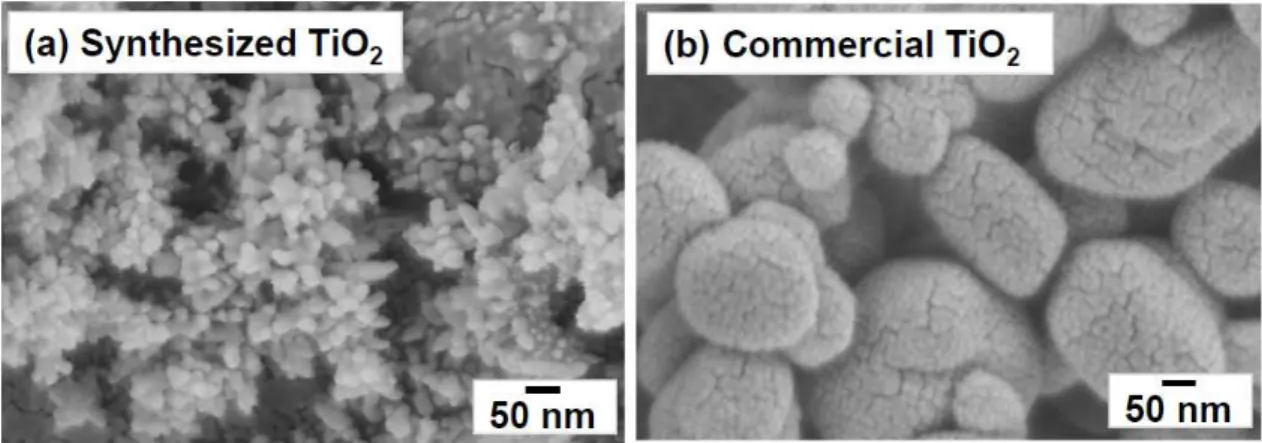
Figure 1 shows FE-SEM images of active material powders of TiO2 alone. We observed
nanoparticles with 10–50 nm in size for TiO2 powder synthesized by a sol-gel method in this study.
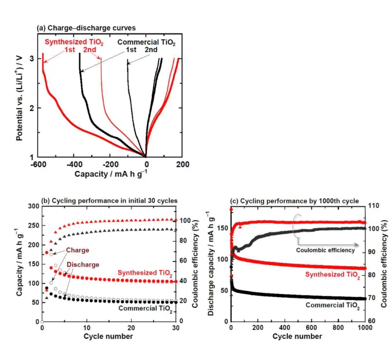
The size is much smaller than that of commercial TiO2 powder. Figure 2(a) shows charge–discharge
(Li+ insertion–extraction) curves at the initial two cycles for the thick-film electrodes prepared by
using rutile-type TiO2 synthesized and commercial one. In the charge processes at the first cycles,
the two TiO2 electrodes exhibited small potential plateaus at around 2.2 V vs. Li/Li+, indicating a
decomposition of the electrolyte. We can recognize more two potential plateaus at 1.4 and 1.2 V vs. Li/Li+. These plateaus are attributed to Li+-insertion into rutile TiO
2 to form LixTiO2, and a partial
phase transformation from TiO2 to hexagonal LiTiO2 [23,32,33], respectively. In the discharge
processes, a potential shoulder appeared at approximately 1.8 V vs. Li/Li+, meaning Li+-extraction
from LixTiO2 [23,32,33]. In the charge process after the second cycle, the plateau at 1.2 V was not
observed because of the irreversible phase transformation to LiTiO2 [23]. The initial Coulombic
efficiencies for the synthesized and commercial TiO2 were 31% and 24%. It is suggested that the low
efficiencies are attributed to the irreversible phase transformation. Figure 2(b) represents dependence of the discharge capacities on cycle number. The capacity of the synthesized TiO2 electrode quickly
reduced within the initial ten cycles, but the electrode exhibited a very stable cycling performance and the discharge capacity of 80–100 mA h g–1 in the subsequent cycles as shown in Fig.2 (c). The capacity is nearly twice larger than that obtained by the electrode of the commercial TiO2. The larger
capacity is probably ascribed to a larger specific surface area of the synthesized TiO2 particles than
the commercial ones. Although the capacity was not so large, the stable performance for a long cycle is very favorable as a material combined with Si.
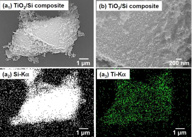
Figure 3 displays an FE-SEM image and the corresponding element mapping results of Si-Kα and Ti-Kα for the TiO2/Si composite powder synthesized by the sol-gel method. These results
Because of the small particle sizes, it is expected that the fast Li-ion diffusion along c-axis of TiO2 is
promoted in the all directions. This probably provides smooth Li+ insertion/extraction of the composite electrodes.
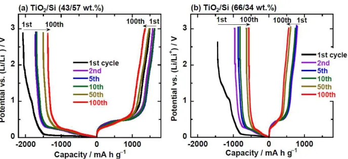
Figures 4(a) and 4(b) show charge–discharge curves in the initial 100 cycles of the TiO2/Si
composite electrodes with weight ratios of 43/57 wt.% and 66/34 wt.%. For every electrode, we clearly observed potential plateaus in the charge and discharge processes at 0.05 V and 0.45 V vs. Li/Li+ at the first cycles. These potential plateaus are attributed to the alloying/dealloying reactions
of Li–Si [1-3,19,22]. After the second cycles, the charge plateaus inclined and rose to 0.1–0.2 V vs. Li/Li+, which has been explained as resulting from amorphization of Si at the first cycle and its
single-phase reaction with Li+ in the subsequent cycles [3].The electrodes behaved very alike until the 100th cycle.
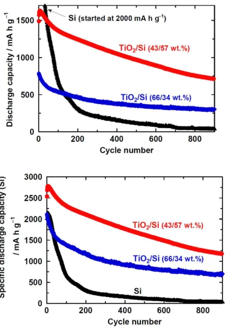
Figure 5(a) presents long-term cycling performance of the TiO2/Si composite electrodes.
Although the Si electrode showed a very large capacity of over 2000 mA h g–1 at the first cycle, a
steep capacity decay was observed by the 100th cycle. The decay is attributed to pulverization and an electrical isolation of the active materials induced by the drastic changes in silicon's volume during Li+-insertion/extraction. On the other hand, the composite electrodes of TiO2/Si (43/57 wt.%)
exhibited an improved performance: a significantly large capacity of 710 mA h g–1 was maintained
even at the 900th cycle. This performance has been much improved in comparison with that of the Si electrode showing only 40 mA h g–1 at the 900th cycle. Furthermore, it is a noteworthy that the
capacity is about two times larger than the theoretical capacity (372 mA h g–1) of practical graphite anode. We consider that the improved performance can be achieved by the fast Li-ion diffusion in TiO2 in the composite electrode. The performance in this study is much better than that of other
composite electrodes of TiO2/Si [37] and TiO2/SiO [38]. The composite electrodes of TiO2/Si (66/34
the theoretical capacity because its initial capacity remained at 790 mA h g–1 owing to the smaller
amount of Si contained in the composite.
To elucidate Li-insertion/extraction properties of Si in the composites, the discharge capacities were converted to capacities per mass of Si on the assumption that TiO2 in the composites shows a
constant capacity of 100 mA h g(TiO2)–1. Figure 5(b) shows that the TiO2/Si electrodes of 43/57
wt.% and 66/34 wt.% exhibited the initial discharge capacities per Si of 2500 and 2100 mA h g(Si)–1. The smaller capacity for the TiO2-rich composite electrode indicates that an excessive TiO2 lowers
an electronic conductivity of composite electrode and thus suppresses alloying/dealloying reactions of Li–Si. On the other hand, at the 4–7th cycles, the composite electrode with 43 wt.% TiO2 showed
a maximum capacity of 2770 mA h g(Si)–1. This value is as high as 77% of the silicon's theoretical capacity (3580 mA h g−1). The high utilization ratio of the electrode, even without any binder or
electronic conductive additive, proves that the fast Li+-diffusion by rutile TiO2 is very important to
enhance a performance of Si-based anode.
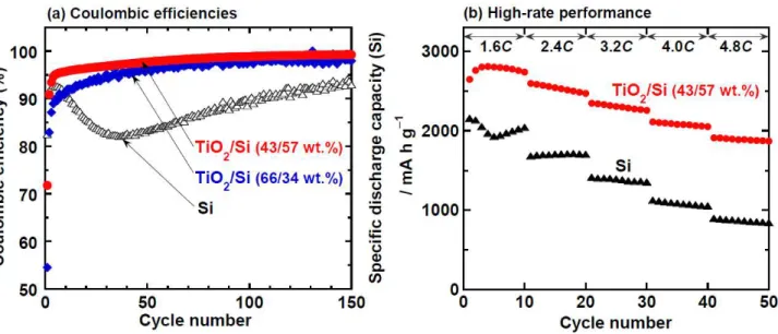
Figure 6(a) compares changes in Coulombic efficiencies of these electrodes. A significant decrease in the efficiency was observed for the Si electrode during the initial 30 cycles. In general, a decreased efficiency of Si-based anode is attributed to a cathodic decomposition of electrolyte and/or pulverization of active material. In this study, we have never observed any obvious potential shoulder of charge-discharge curves for the Si electrode (see Fig. S4). The decrease indicates that the active material layer showed a breakup by the pulverization of Si and was electrically isolated. At the first cycle, the composite electrodes with TiO2 ratios of 43 wt.% and 66 wt.%, respectively, exhibited
lower efficiencies of 72% and 56% compared with the Si electrode (83%). The efficiencies of the composite electrodes, however, monotonically rose with increasing cycle number. In particular, TiO2/Si (43/57 wt.%) electrode maintained improved efficiency of over 98% from the 60th cycle. In
fact, FE-SEM observations of the electrodes revealed that many cracks were observed for the Si electrode surface after charge–discharge cycles, whereas the breakup of active material layer was
relatively suppressed in case of the TiO2/Si electrode (Fig. S3). We suggested that
alloying/dealloying reactions occur only near the surface of Si electrode because of slow Li-ion diffusion in Si, thereby causing a stress accumulation near the surface based on silicon's volume changes. In contrast, fast Li-ion diffusion in TiO2 presumably enables efficient electrode reactions in
the whole active material layer.
A diffusion depth from the electrode surface is here discussed by estimating a root-mean-square displacement of Li+ diffusion. In case of one-dimensional diffusion, the root-mean-square
displacement L can be estimated by the diffusion time t and an equation of L = (2 DLi+ t )1/2.
In the experiment for the Si electrode, the first charge process time was 2520 s under the current density of 3.5 A g–1 (1.0C). By using the DLi+ of 10–12 cm2 s–1, the equation gives L = 0.7 µm for Si.
If we assume that the Si thick-film has a fully dense structure and a typical thickness of 2 µm, Li ions can diffuse by the depth of about half of the film thickness. This estimation suggests that only a part of Si near the surface is lithiated owing to the kinetic restriction of Li+ diffusion though there are actually many interspaces in the electrode because the GD thick-films consist of cohesive aggregates of the powder [9,22]. In contrast, when we assume that randomly oriented rutile TiO2 shows DLi+ of
10–6 cm2 s–1, L = 700 µm can be obtained. This value is three orders of magnitude larger than that of Si. We can consequently expect that Li ions can reach whole active material layer in the TiO2/Si
composite electrodes. The composite electrode, therefore, could relatively avoid the stress accumulation near the surface. These results indicate that the existence of TiO2 is very effective to
exert the high theoretical capacity of Si.
Figure 6(b) represents an improved high-rate performance of the TiO2/Si composite electrode. In
this figure, discharge capacities of the composite were converted to capacities per mass of Si. The composite electrode maintained a very large capacity of over 1870 mA h g(Si)–1 even at a high rate of 4.8C. It is clearly demonstrated that the smooth Li-ion transfer in the composite electrode can
considerably enhance the discharge capacity at high-rate charge–discharge. Consequently, we revealed that the composite of rutile-type TiO2 and Si is a very promising anode material for the
next-generation Li-ion battery with a good high-rate performance as well as with a high discharge capacity. Note that even in the absence of any buffer material or electronic conductive material, the TiO2/Si composite electrodes perform the improved anode properties. It is well known that TiO2 is
very hard material: the Mohs hardness of 6.0–6.5 in rutile TiO2 is as high as that of 7.0 in Si. In
addition, TiO2 has a high electrical resistivity. Nevertheless, the binder-free TiO2/Si composite
electrode exhibited the improved performance, which makes us strongly expect that the performance can be further improved by using suitable buffer material and electronic conductive material.
4. Conclusions
We synthesized TiO2/Si composite powders for Li-ion battery anode by the sol-gel method, and
evaluated the electrochemical properties of the thick-film electrodes prepared by GD using the composites. The Si surface of the composites was uniformly covered by rutile TiO2 nanoparticles
with 10–50 nm in size. The remarkably improved performance was obtained for the composite electrodes of TiO2/Si (43/57 wt.%): the discharge capacity of 710 mA h g–1 could be achieved even
at the 900th cycle. It is notable result that the discharge capacity after such long cycles is about two times larger than the theoretical capacity of the graphite anode. In addition, the electrode showed the remarkable high-rate performance: the large capacity of over 1870 mA h g(Si)–1 was maintained even at a high rate of 4.8C. We consider that the fast Li-ion diffusion in rutile TiO2 improves Li-ion
transfer in the composite electrode, resulting in a significant enhancement of the anode performance.
This work was partially supported by a Grant-in-Aid for Scientific Research from the Ministry of Education, Culture, Sports, Science and Technology (MEXT) of Japan. A part of this work was supported by a research grant from the Murata Science Foundation, and from the Japan Association for Chemical Innovation (JACI).
References
[1] T. D. Hatchard and J. R. Dahn, J. Electrochem. Soc., 151 (2004) A838.
[2] M. N. Obrovac and L. Christensen, Electrochem. Solid-State Lett., 7 (2004) A93.
[3] M. N. Obrovac and L. J. Krause, J. Electrochem. Soc., 154 (2007) A103.
[4] N. Ding, J. Xu, Y. X. Yao, G. Wegner, X. Fang, C. H. Chen, I. Lieberwirth, Solid State Ionics,
180 (2009) 222.
[5] J. Xie, N. Imanishi, T. Zhang, A. Hirano, Y. Takeda, O. Yamamoto, Mater. Chem. Phys., 120 (2010) 421.
[6] G. Zhao, Y. Meng, N. Zhang, K. Sun, Mater. Lett., 76 (2012) 55.
[7] V. A. Sethuraman, M. J. Chon, M. Shimshak, V. Srinivasan, P. R. Guduru, J. Power Sources,
195 (2010) 5062.
[8] H. Sakaguchi, H. Honda, Y. Akasaka, T. Esaka, J. Power Sources, 119–121 (2003) 50.
[9] H. Sakaguchi, T. Toda, Y. Nagao, T. Esaka, Electrochem. Solid-State Lett., 10 (2007) J146.
[10] T. Iida, T. Hirono, N. Shibamura, H. Sakaguchi, Electrochemistry, 76 (2008) 644.
[11] H. Sakaguchi, T. Iida, M. Itoh, N. Shibamura, T. Hirono, IOP Conf. Series: Mater. Sci. Eng., 1 (2009) 012030.
[12] H. Usui, Y. Kashiwa, T. Iida, H. Sakaguchi, J. Power Sources, 195 (2010) 3649.
[13] H. Usui, H. Nishinami, T. Iida, H. Sakaguchi, Electrochemistry, 78 (2010) 329.
[14] H. Usui, M. Shibata, K. Nakai, H. Sakaguchi, J. Power Sources, 196 (2011) 2143.
[16] H. Usui, N. Uchida, H. Sakaguchi, J. Power Sources, 196 (2011) 10244.
[17] H. Usui, T. Kono, H. Sakaguchi, Int. J. Electrochem. Sci., 7 (2012) 4322.
[18] H. Usui, N. Uchida, H. Sakaguchi, Electrochemistry, 80 (2012) 737.
[19] H. Usui, M. Shimizu, H. Sakaguchi, J. Power Sources, 235 (2013) 29.
[20] H. Usui, Y. Yamamoto, K. Yoshiyama, T. Itoh, and H. Sakaguchi, J. Power Sources, 196 (2011) 3911.
[21] H. Usui, T. Masuda, H. Sakaguchi, Chem. Lett., 41 (2012) 521.
[22] H. Usui, Y. Kiri, H. Sakaguchi, Thin Solid Films, 520 (2012) 7006.
[23] Y.-S. Hu, L. Kienle, Y.-G. Guo, J. Maier, Adv. Mater., 18 (2006) 1421.
[24] D. Deng, M. G. Kim, J. Y. Lee, J. Cho, Energy Environ. Sci., 2 (2009) 818.
[25] P. Yu, B. N. Popov, J. A. Ritter, R. E. White, J. Electrochem. Soc., 146 (1999) 8.
[26] L. Kavan, M. Grätzel, S. E. Gilbert, C. Klemenz, H. J. Scheel, J. Am. Chem. Soc., 118 (1996) 6716.
[27] A. A. Belak, Y. Wang, A. V. Ven, Chem. Mater., 24 (2012) 2894.
[28] F. Wunde, F. Berkemeier, G. Schmitz, J. Power Sources, 215 (2012) 109.
[29] T.-F. Yi, H. Liu, Y.-R. Zhu, L.-J. Jiang, Y. Xie, R.-S. Zhu, J. Power Sources, 215 (2012) 258.
[30] M. A. Reddy, M. S. Kishore, V. Pralong, V. Caignaert, U. V. Varadaraju, B. Raveau, Electrochem. Commun., 8 (2006) 1299.
[32] E. Baudrin, S. Cassaignon, M. Koelsch, J.-P. Jolivet, L. Dupont, J.-M. Tarascon, Electrochem. Commun., 9 (2007) 337.
[33] M. Marinaro, M. Pfanzelt, P. Kubiaka, R. Marassi, M. Wohlfahrt-Mehrens, J. Power Sources,
196 (2011) 9825.
[34] C.-C. Wang and J. Y. Ying, Chem. Mater., 11 (1999) 3113.
[35] T. Sasamoto, S. Enomoto, Z. Shimoda, Y. Saeki, J. Ceramic Soc. Jpn., 101 (1993) 230.
[36] Y. Wang, L. Zhang, K. Deng, X. Chen, Z. Zou, J. Phys. Chem. C, 111 (2007) 2709.
[37] Z. Y. Zeng, J. P. Tu, X. H. Huang, X. L. Wang, X. B. Zhao, K. F. Li, Electrochem. Solid-State Lett., 11 (2008) A105.
Table 1. Electrochemical properties of some candidates for the next-generation anode materials: their theoretical capacity, volume expansion ratio at lithiation, and diffusion coefficient of Li+.
Figure 1. FE-SEM images of active material powders of TiO2 alone before GD: (a) TiO2 powder
Figure 2. Electrochemical properties for thick-film electrodes prepared by using synthesized TiO2
and commercial TiO2 as Li-ion battery anode. (a) Charge–discharge potential profiles at initial two
cycles. (b) Charge capacities, discharge capacities, and Coulombic efficiencies in initial 30 cycles. Charge capacity of synthesized TiO2 at the first cycle was 570 mA h g–1, which is not shown in this
Figure 3. (a1) FE-SEM image of TiO2/Si composite powder synthesized by sol-del method.
Elemental mapping results of the corresponding TiO2/Si composite for (a2) Si-Kα and (a3) Ti-Kα.
Figure 4. Charge–discharge curves of TiO2/Si composite electrodes in initial 100 cycles. Weight
Figure 5. (a) Long-term cycling performance of TiO2/Si composite electrodes. For comparison,
cyclability of Si electrode was also shown in the figure. (b) Variation in discharge capacities converted to capacities per mass of Si in TiO2/Si composites.
Figure 6. (a) Changes in Coulombic efficiencies of TiO2/Si composite electrodes. (b) High-rate
charge–discharge performance of TiO2/Si composite electrode and Si electrode at current rate
between 1.6C and 4.8C. Note that discharge capacities of composite electrode were converted to capacities per mass of Si.
Figure captions
Table 1. Electrochemical properties of some candidates for the next-generation anode materials: their theoretical capacity, volume expansion ratio at lithiation, and diffusion coefficient of Li+.
Figure 1. FE-SEM images of active material powders of TiO2 alone before GD: (a) TiO2 powder
synthesized by sol-gel method, (b) commercial TiO2 powder.
Figure 2. Electrochemical properties for thick-film electrodes prepared by using synthesized TiO2
and commercial TiO2 as Li-ion battery anode. (a) Charge–discharge potential profiles at initial two
cycles. (b) Charge capacities, discharge capacities, and Coulombic efficiencies in initial 30 cycles. Charge capacity of synthesized TiO2 at the first cycle was 570 mA h g–1, which is not shown in this
figure. (c) Variation in discharge (Li+-extraction) capacity vs. cycle number for 1000 cycles.
Figure 3. (a1) FE-SEM image of TiO2/Si composite powder synthesized by sol-del method.
Elemental mapping results of the corresponding TiO2/Si composite for (a2) Si-Kα and (a3) Ti-Kα.
(b) Corresponding higher magnification image.
Figure 4. Charge–discharge curves of TiO2/Si composite electrodes in initial 100 cycles. Weight
Figure 5. (a) Long-term cycling performance of TiO2/Si composite electrodes. For comparison,
cyclability of Si electrode was also shown in the figure. (b) Variation in discharge capacities converted to capacities per mass of Si in TiO2/Si composites.
Figure 6. (a) Changes in Coulombic efficiencies of TiO2/Si composite electrodes. (b) High-rate
charge–discharge performance of TiO2/Si composite electrode and Si electrode at current rate
between 1.6C and 4.8C. Note that discharge capacities of composite electrode were converted to capacities per mass of Si.