1
Enhancement in Boiling Heat Transfer for Water Using a Polished Plate
Surface
Masahiro KATOH1, Norimasa YOSHIDA2, Naoto YAMADA2, Daiki MINE2, Kenji OHNISHI3,
Daisuke YONEKURA4, and Shigeru SUGIYAMA1
1Department of Applied Chemistry, Graduate School of Technology, Industrial and Social Sciences, Tokushima University, 2-1 Minamijosanjima-cho, Tokushima-shi, Tokushima 770-8506, Japan 2Department of Chemical Science and Technology, Tokushima University, 2-1 Minamijosanjima-cho, Tokushima-shi, Tokushima 770-8506, Japan
3Daikatech Co. LTD., 9-1 Yonezu, Kawauchi-cho, Tokushima-shi, Tokushima 771-0139, Japan 4Department of Mechanical Engineering, Graduate School of Technology, Industrial and Social Sciences, Tokushima University, 2-1 Minamijosanjima-cho, Tokushima-shi, Tokushima 770-8506, Japan
Keywords: Boiling Heat Transfer Enhancement, Water, Plate Heat Transfer, Polished Plate Surface
The thermal characteristic of a plate evaporator for boiling water have been experimentally investigated. Stainless-steel plates with five kinds of surface roughness (a mirror-polished surface and four kinds of polished plate surface, F2, F0, F-1, and F-2 polishing) were used for the investigation. The roughness order is F-2 > F-1 > F0 > F2 > mirror. The local boiling heat transfers were measured on the evaporator surface using ten thermocouples inside the evaporator. For a comparison of the heat transfer characteristic of the evaporator, the local boiling heat transfer coefficient was measured when the polishing direction was perpendicular or parallel to the water flow at a range of pressures (0.3–0.4 MPa) and flow rates (20–60 mL/min). The results indicate that the local heat transfer coefficient increased with increasing vapor quality at all surface conditions. For F0 polishing, the heat transfer coefficient on the surface with perpendicular polishing was much larger than that on the surfaces with parallel and mirror polishing. In particular, the heat transfer coefficient of the perpendicularly polished surface (F2 and F0 polishing) was increased six-fold in comparison with that of the mirror surface at a vapor quality of 0.35. However, for the F-1 and F-2 perpendicularly polishing plates, the heat transfer coefficients were smaller than those of the F0 and F2 perpendicularly polishing plates. For the F2 perpendicularly polished plate, heat transfer enhancement was confirmed, along with an increase in the number of bubbling points, on increasing the system pressure. For the polished surface, the heat transfer coefficient increased with increasing flow rate. This indicates that the bubble formation cycle was promoted by an increased flow rate.
Introduction
In many industries, plate heat exchangers are used because of their high efficiency, easy maintenance, and small size (Li et
al., 2010). However, further reduction in the energy requirement
is necessary. Use of an uneven plate surface is an easy way to enhance heat transfer by increasing the heat transfer area and generating a swirling current (Wang et al., 2003; Turk et al., 2016). Recently, many studies on millimeter-order uneven heat plates have been reported. Piper et al. (2016) reported the numerical investigation of turbulent forced convection heat transfer in pillow plates.
However, studies of micro- or nanoscale fine fabricated heat plates are scarce. Okamoto et al. (2010) reported the local heat transfer coefficient of a micro-grooved surface was remarkably larger (10–40%) than that of a flat surface. In their study, the depth of flutes for plates was 30 µm, and the width of the protrusions was 100 µm.
Received on XXXXXX; Accepted on XXXXXX DOI:
Corresponding concerning this article should be addressed to M. Katoh (E-mail address: [email protected]).
We have focused on our unique fabricated technique, so-called “F polishing” (Katoh et al., 2008; Yonekura et al., 2010; Yonekura et al., 2011). As we have previously reported, an anti-adhesion effect of particles is observed on these uniquely fabricated steel plates. In this study, we have aimed to enhance heat transfer by applying this technology to the heat transfer surface of a plate heat exchanger.
1. Experimental
In this study, SUS 304 stainless steel was used. The surface of the plate was mirror polished using waterproof abrasive papers (#180–#2000) and alumina powders (particle diameter: 0.3 µm). The F-polished surfaces were unidirectionally polished using four kinds of polishing material on the mirror surface (Katoh et al., 2008). Hereafter, the four polishing conditions are denoted F2, F0, F-1, and F-2. The difference is only the grain size of the polishing materials used. The roughness was measured using a Surface Profiler (Dektak, Veeco Instruments Inc.). The root mean square roughness of the five types of polished SUS surfaces are shown in Table 1. Scanning electron microscopy (SEM) and atomic force microscopy (AFM) images of the polished SUS surface were obtained using a SEM
(TM-2
1000, Hitachi High-Technologies Corp.) and an AFM (Nano Wizard II, JPK Instruments AG), respectively. Figures 1 and 2 show SEM and AFM images of the five kinds of polishing SUS surface. Heat transfer plates with four kinds of F polishing surfaces were used, in order of surface roughness, these are F-2, F-1, F0, and F2. A mirror-polished plate was also prepared for comparison. Polishing mirror F2 F0 F-1 F-2 Surface roughness Rq [nm] 6 71 206 552 655Figure 3 shows the experimental setup, which consists of a
heat transfer test plate, a pre-heater, an oil bath, a feed pump, and coolers (Koyama et al., 2014). Figure 4 shows the heat transfer test plate. The plate consists of microfabricated SUS304 heat transfer plate and aluminum heater block. Figure 4 also shows the location of thermocouples in the plate. Ten thermocouples were embedded in the plate, and five of them are located close to the passage. Pairs of thermocouples were set every 59 mm along the working fluid flow direction. Figure 5 shows the detailed configuration of a pair of thermocouples; each pair is separated by 40-mm intervals to allow the measurement of the temperature distribution in the test plate. The experimental procedure was as follows. First, distilled water (the working
fluid) was circulated through the setup at an arbitrary flow rate. Then, the fluid was heated by the pre-heater and the heater attached to the heat transfer test plate. After the desired experimental conditions had been obtained and a steady state had been reached, the temperatures of the test plates were measured. In this study, the effects on the heat transfer performance of the test plates were investigated by changing the flow rate of the working fluid, the system pressure, and the heater output. The experimental conditions in this study are shown in Table 2.
2. Data Reduction
The local heat transfer coefficient and vapor quality were
Parameter Range
Flow rate of the working
fluid [mL/min] 20, 40, 60
System pressure [MPa] 0.3, 0.4, 0.45, 0.5 Heater output [W] 360, 640, 1000 Outlet temperature of
pre-heater [℃] 60–138.7
Fig. 3 Schmatic diagram of the experimental setup.
Table 2 Experimental conditions. Fig. 4 Configration of the heat transfer plate in the
experimental setup.
Table 1 The root mean square roughness (Rq) of the five
kinds of polished SUS surfaces.
Fig. 5 Configration of a pair of thermocouples.
Fig. 1 SEM images of the five kinds of polished SUS
surfaces: (a) mirror, (b) F2, (c) F0, (d) F-1, and (e) F-2.
Fig. 2 AFM images of the five kinds of polished SUS
surfaces: (a) mirror, (b) F2, (c) F0, (d) F-1, and (e) F-2.
3
calculated in this study (Koyama et al., 2014). The local heat flux, q, was obtained using Eq. (1) and the data from the five pairs of thermocouples, as shown in Figure 4. Eq. (1) is derived from the one-dimensional heat conduction equation𝑞𝑞 = 𝑘𝑘sus𝑇𝑇1−𝑇𝑇𝑙𝑙12 (1)
The Plate surface temperature Twall, is calculated by
extrapolation:
𝑇𝑇𝑤𝑤𝑤𝑤𝑙𝑙𝑙𝑙= 𝑇𝑇2−𝑘𝑘𝑞𝑞𝑙𝑙𝑠𝑠𝑠𝑠𝑠𝑠2 (2)
Then, the local heat transfer coefficient h, is obtained: ℎ =𝑇𝑇 𝑞𝑞
𝑤𝑤𝑤𝑤𝑤𝑤𝑤𝑤−𝑇𝑇𝑠𝑠𝑤𝑤𝑠𝑠 (3)
The local vapor quality is obtained using Eq. 4: x𝑛𝑛=𝑖𝑖test,n𝑖𝑖−𝑖𝑖𝑓𝑓𝑓𝑓𝑠𝑠𝑤𝑤𝑠𝑠,𝑤𝑤𝑙𝑙𝑙𝑙 (𝑛𝑛 = 1– 5) (4)
First, the specific enthalpy at the heat test plate entrance (itest,in) was calculated using Eq. 5.
𝑖𝑖𝑡𝑡𝑡𝑡𝑡𝑡𝑡𝑡,𝑖𝑖𝑛𝑛= 𝑖𝑖𝑡𝑡𝑤𝑤𝑡𝑡.𝑙𝑙𝑖𝑖𝑞𝑞− 𝑐𝑐(𝑇𝑇𝑡𝑡𝑤𝑤𝑡𝑡− 𝑇𝑇𝑖𝑖𝑛𝑛) (5)
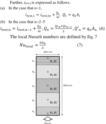
Next, the local specific enthalpy (itest,n) at temperature measuring
point n, as shown in Figure 6, was calculated by adding the increase in the specific enthalpy at the plate entrance (Arima et
al., 2010).
Further, itest,n is expressed as follows.
(a) In the case that n=1,
𝑖𝑖𝑡𝑡𝑡𝑡𝑡𝑡𝑡𝑡,1= 𝑖𝑖𝑡𝑡𝑡𝑡𝑡𝑡𝑡𝑡,𝑖𝑖𝑛𝑛+𝑄𝑄𝑚𝑚1, 𝑄𝑄1= 𝑞𝑞1𝐴𝐴1
(b) In the case that n=2–5
𝑖𝑖𝑡𝑡𝑡𝑡𝑡𝑡𝑡𝑡,𝑛𝑛= 𝑖𝑖𝑡𝑡𝑡𝑡𝑡𝑡𝑡𝑡,𝑛𝑛−1+𝑄𝑄𝑚𝑚𝑛𝑛, 𝑄𝑄𝑛𝑛=𝑄𝑄′𝑛𝑛+𝑄𝑄′2 𝑛𝑛−1, 𝑄𝑄′𝑛𝑛= 𝑞𝑞𝑛𝑛𝐴𝐴𝑛𝑛 (6) The local Nusselt numbers are defined by Eq. 7
𝑁𝑁𝑁𝑁𝑙𝑙𝑙𝑙𝑙𝑙𝑤𝑤𝑙𝑙=ℎ𝐷𝐷𝜆𝜆ℎ (7)
3. Results and Discussion
The thermal characteristics of boiling water flow in a plate evaporator were experimentally investigated. The effects of the type of F-polishing, pressure, and flow rate on the local heat transfer coefficient are discussed.
3.1 Effect of polishing direction
Figure 7 shows the local heat transfer coefficient (h) for
F0 and F-2-polished surfaces polished in two different directions (perpendicular or parallel) with respect to the direction of water flow, as well as that of a mirror surface. The figure shows the changes in the local heat transfer coefficient with vapor quality at the set operating conditions (flow rate: 40 mL/min, heater output: 1000 W, system pressure: 0.3 MPa). According to Figure 7, for a parallel polished plate, the local heat transfer coefficient increased slightly with increasing vapor quality. The coefficients for F0 and F-2 polished plates were almost the same as that of the mirror-polished plate, and the coefficient was independent of the surface roughness. On the other hand, for the perpendicularly polished plates, the coefficient increased sharply with increasing vapor quality. The coefficient of the F0-polished plate was higher than that of F-2-polished plate. Furthermore, the perpendicularly F-2-polished plates showed better heat transfer characteristics than the parallel and mirror-polished plates.These results indicate that perpendicular F polishing was effective under boiling conditions with nuclear boiling. An enhancement in the heat transfer was obtained when using perpendicular F polishing. In the case of perpendicular polishing, the flow is continuously subjected to a rough surface, resulting in vortex flow. The vortex flow separates the superheated liquid layer from the heat transfer surface and accelerates the bubble formation cycle. Thus, the vortex flow contributes to the enhancement of heat transfer performance. On the other hand, in the case of parallel polishing, the roughness that causes vortex flow is not in the flow direction, and the vortex flow does not occur. The valued of h for F0 and F-2 parallel-polished surfaces are very similar that of mirror surface. Thus, all polishing was carried out perpendicular to the water flow direction.
3.2 Effect of pressure drop
Figure 8 shows the pressure drops for three kinds of plate
surfaces (F0, F-2, and mirror polished). The results showed pressure drop increased with increasing heater output (a) and flow rate (b). Concerning heater output (a), the heat quantity provided to a heat transfer plate from the heater increased with increasing heater output. As a result, the temperature difference between the temperature of the working fluid and the saturated temperature increased with increasing plate surface temperature. By increasing the temperature difference, nucleate boiling was promoted, the vapor quality in the flow channel increased and
Fig. 7 Comparison of local heat transfer coefficient versus
vapor quality for F0 and F-2-polished plates and perpendicular or parallel polishing directions, as well as that for a mirror-polished plate
Fig. 6 Schematic diagram of the effective heat transfer
4
the pressure drop increased. On the other hand, concerning the flow rate (b), it is thought that the influence of forced convection was dominant. Because the area of flow channel exit was small, pressure drop increased with increasing flow rate. However, these tendencies were not dependent on the polishing surface.3.3 Effect of polishing the surface
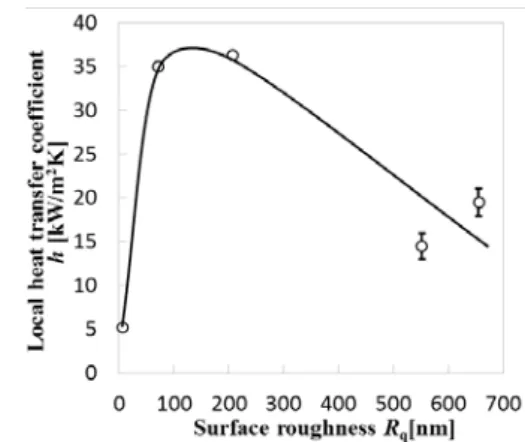
Figure 9 shows the local heat transfer coefficient (h) for
the five types of plate surfaces. The figure shows the changes in
h with vapor quality for the different operating conditions (flow
rate: 40 mL/min, heater output: 1000 W, system pressure: 0.3 MPa). As shown in Figure 9, h decreased in the order F0 > F2 > F-2 > F-1 > mirror; in addition, h is dependent on the differences in the roughness of the F2 and F0-polished plates at a vapor quality of around 0.2. We believe that the difference depends on the flow-pattern (Arima et al., 2010). The difference is remarkable from nuclear boiling to slug flow at a vapor quality of ca. 0.2, but the difference is negligible in annular flow at a vapor quality of 0.35. In the vapor quality range of 0.3 to 0.4, values of h approximately six-times that of the mirror-polished plate were observed for the F0- and F2-polished plates. However, for the F-1 and F-2-polishing plate, the heat transfer coefficients were smaller than those of F0 and F2-polished plates, and the local heat transfer coefficient was approximately three times that of the mirror-polished plate. The local heat transfer coefficient at a vapor quality of 0.35 of the different types of polished surface are summarized in Figure 10.
Based on these results, a significant heat transfer enhancement was confirmed with F-polished plates for heat transfer in boiling water. Possibly, many cavities were formed, which could yield bubbling points in the case of boiling induced by F polishing. Because the F-1 and F-2-polished surfaces have
large surface roughness values, the individual cavities were larger than those of the F0 and F2-polished surfaces. As a result, the number of possible bubbling points decreased. In the studied experimental range, we found that the number and frequency of cavities contributed significantly more to the improvement of thermal conductivity than the size of the cavities.
3.4 Effect of system pressure
Figure 11 shows the heat transfer coefficients for two
kinds of plate surfaces (F2 and F0). The figure shows the changes in local heat transfer coefficient with vapor quality at set operating conditions (flow rate: 40 mL/min, heater output: 1000 W, system pressure: 0.3 or 0.4 MPa). Although the coefficient is independent of the pressure on the F0-polished plate, the coefficient increased with increasing pressure above a vapor quality of 0.3 for the F2-polished surface. This result indicates that there was a heat transfer enhancement and an increase in the number of bubbling points with increasing pressure for the low-roughness F2 plate because the number of active cavities on the plate surface increased with increasing pressure (Jpn. Soc. Mech. Eng. 2005). That is, under low pressure, larger active cavities only are used as bubbling points. However, at high pressure, water can enter the smaller active cavities and boil at the boiling points.
3.5 Effect of flow rate
Figure 12 shows the heat transfer coefficients for three
kinds of plate surfaces (F2, F0, and F-2).The figure shows the changes in the local heat transfer coefficient with vapor quality at different operating conditions (flow rate: 20, 40 and 60 mL/min, heater output: 1000 W, system pressure: 0.3 MPa). For all polishing conditions, the coefficient increased with
Fig. 9 Comparison of the local heat transfer coefficient
versus vapor quality for different polished plates.
Fig. 10 Relationship of local heat transfer coefficient and
surface rooughness.
Fig. 11 The relationship between vapor quality and the
local heat transfer coefficient on each plate at different pressures: (a) F2 and (b) F0.
Fig. 8 Comparison of the pressure drop at F0, F-2, and
mirror polished plates with (a) heater output and (b) flow rate.
5
increasing flow rate because the bubble formation cycle in the boiling water was promoted by the increasing flow rate.Figure 13 shows the Nusselt numbers (Nu) for three kinds
of plate surfaces (F2, F0, and F-2) at a vapor quality of 0.2. Nu increased with increasing flow rate for all polishing conditions. The difference in Nu with polishing condition became significant as the flow rate increased. The results indicate that the local heat transfer coefficient increases with increasing flow rate.
Conclusions
In this study, the effects of polishing SUS surface on boiling water heat transfer were investigated, and the following conclusions were drawn.
1. An enhancement in heat transfer on the F-polished plates was confirmed under various operating conditions. 2. For the F0 or F-2-polished surfaces, the heat transfer
coefficient on the surfaces polished perpendicularly to the water flow direction was much larger than that on the surfaces with parallel and mirror polishing.
3. For the F0 and F2 perpendicularly polished plates, a heat transfer enhancement of ca. six-times that of the mirror-polished plate was obtained at vapor qualities of 0.3 to 0.4. However, for the F-1 and F-2 perpendicularly polished plates, the heat transfer coefficients were smaller than those of the F0 and F2-polished plates.
4. In the studied experimental range, the number and frequency of the cavities contributed more significantly to the improvement in thermal conductivity than the size of the cavities.
Acknowledgement
The authors gratefully acknowledge Dr. Yanagiya (Graduate School of Technology, Industrial and Social Sciences, Tokushima University) for his technical support with AFM measurements.
Nomenclature
An = local heat transfer area [m2]
C =specific heat [J/kg・K]
Dh = heated equivalent diameter [m]
h = heat transfer coefficient [W/m2K] itest,in = specific enthalpy at the heat transfer test plate entrance
[J/kg]
itest,n = local specific enthalpy in test plate [J/kg]
ifg = latent heat of evaporation [J/kg]
isat,liq = specific enthalpy of saturated liquid [J/kg]
ksus = thermal conductivity of the heat transfer plate
[W/m・K]
l1 = distance between a pair of the heat transfer surface and
the working fluid side of the thermocouple [m]
l2 = distance between a pair of thermocouples [m]
m = mass flow rate [kg/s]
N = segment number [—]
Nu = Nusselt number [—]
Qn = local heat flow [W]
q = heat flux [w/m2]
qn = local heat flux [W/m2]
T1 = plate temperature of heater side [℃]
T2 = plate temperature of flow channel side [℃]
Tin = temperature at the heat transfer test plate entrance [℃]
Tsat = saturation temperature [℃]
Twall = surface temperature of the heat transfer plate [℃]
χ = vapor quality [—]
λ = water thermal conductivity [W/m・K]
Literature Cited
Arima, H., J. H. Kim, A. Okamoto, and Y. Ikegami, “Local Boiling Heat Transfer Characteristics of Ammonia in a Vertical Evaporator,” Int. J. Refrigeration, 33, 359-370(2010)
Jpn. Soc. Mech. Eng.; Heat Transfer, pp.131-132, Showa Information Process Co. Ltd., Tokyo, Japan (2005) Katoh, M., D. Yonekura, and K. Ohnishi, “Powder Handling
Machine and Steel Plate for Powder Handling Machine,” Japanese Patent 4064438(2008)
Koyama, K., H. Chiyoda, H. Arima, and Y. Ikegami, “Experimental Study on Thermal Characteristics of Ammonia Flow Boiling in a Plate Evaporator at low Mass Flux,” Int. J. Refrigeration, 38, 227-235(2014)
Li, X-W., J-A. Meng, and Z-X. Li, “An experimental study of the flow and heat transfer between enhanced heat transfer plates for PHEs,” Exp. Thermal Fluid Sci., 34, 1194-1204 (2010)
Okamoto, A., H. Arima, and Y. Ikegami, “Boiling Heat Transfer Enhancement for Ammonia Using Micro-Grooved Surface on Titanium Plate Evaporator,” KOBE STEEL
ENGINEERING REPORTS, 60, 60-65 (2010)
Piper, M., A. Zibart, J. M. Tran, and E. Y. Kenig, “Numerical Investigation of Turbulent Forced Convection Heat Transfer in Pillow Plates,” Int. J. Heat. Mass Trans., 94, 516-527 (2016)
Turk, C., S. Aradag, and S. Kakac, “Experimental Analysis of a Mixed-Plate Gasketed Plate Heat Exchanger and Artificial Neural Net Estimations of the Performance as an Alternative to Classical Correlations,” Int. J. Therm. Sci.,
109, 263-269 (2016) Fig. 12 The relationship between vapor quality and local
heat transfer coefficient on each plate at different flow rate: (a) F2, (b) F0, and (c) F-2.
Fig. 13 Relationship between flow rate and Nusselt
6
Wang, L., B. Sunden, and R. M. Manglik, “Plate HeatExchangers: Design, Applications and Performance (Development in Heat Transfer),” Wit Press / Computational Mechanics Publications(2003)
Yonekura, D., M. Takahashi, R. Murakami, M. Katoh, and K. Ohnishi, “Influence of Surface Polishing of Steel Plate on Adhesion/Heap Behavior of Silica Powder,” Trans., Japan
Soc. Mechanical Eng., (C), 76, 1838-1843 (2010)
Yonekura, D., M. Takahashi, R. Murakami, M. Katoh, and K. Ohnishi, “Influence of Particle Size on Anti-Adhesion Effect of Surface Polished Steel Plate,” Trans., Japan Soc.