3D Modeling of Wide Area Outdoor Environments by Integrating Omnidirectional Range and Color Images
2
0
0
全文
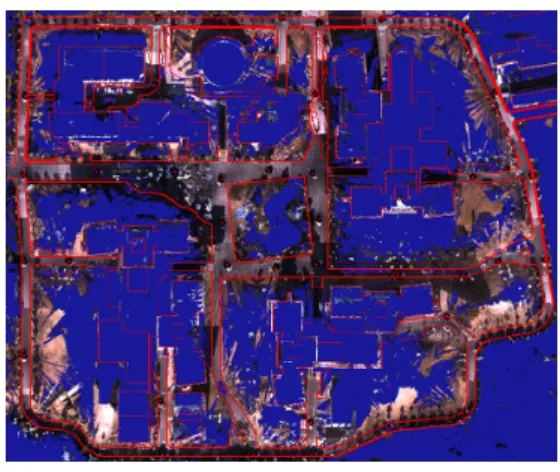
(2) ISMAR 2004. distance by rotating the laser scan, thus the spatial density of data points depends on the distance; that is, close objects are measured densely and far objects are measured sparsely. This causes a problem in registering range data obtained at different positions. In order to overcome this problem, we define an error by computing the distance between a point in one data set and a plane determined by adjacent points in the other data set. Whole model is generated by sequentially registering a pair of range data whose acquired positions adjoin each other.. 2.3. Integrating Range and Color Images The 3D shape obtained in the previous section is texture-mapped by omnidirectional color images. The position and orientation of OMS are also simultaneously estimated by registering range images because geometrical relationship between the rangefinder and the OMS is fixed and aligned. Each triangular patch on the 3D shape is colored by the texture from the image which gives the highest resolution. However, this strategy fails when an occlusion occurs. The occlusion is detected when the whole 3D shape intersects with a triangular pyramid determined by triangular patch vertexes and the projection center of camera. In such a case, the second highest resolution image is selected.. This paper has proposed a 3D modeling method which is based on integrating omnidirectional range and color images for wide area outdoor environments. In experiments, a 3D model is actually generated from omnidirectional range and color images acquired at 50 points in our campus. Moreover, we can move viewpoint and look around the model freely.. 3. Experiments. Reference. Fig.2 2D CAD data and a generated model. Examples of rendering the generated model are shown in Fig. 3.. 4. Conclusion. We have carried out experiments of reconstructing our campus. In experiments, the range and color images are acquired at 50 points in our campus (about 200m x 300m). The resolution of each range image is 904 x 450. The transformation matrix between rangefinder and OMS coordinates is estimated by pairing corresponding points in a range and a color image manually. The antenna of the RTK-GPS is installed in a site measurable from the rangefinder. The number of polygons of the generated 3D model is 2,930,462. Fig. 2 illustrates a 2D CAD data of our campus with the generated model data. We confirm that the generated model has no large distortion.. [1] C. Früh and A. Zakhor: “Constructing 3D city models by merging aerial and ground views,” IEEE Computer Graphics and Applications, Vol. 23, pp. 52-61, 2003. [2] T. Sato, M. Kanbara, N. Yokoya, and H. Takemura: “Dense 3-D reconstruction of an outdoor scene by hundreds-baseline stereo using a hand-held video camera”, International Jour. of Computer Vision, Vol. 47, No. 1-3, pp. 119-129, 2002. [3] S. Ikeda, T. Sato, and N. Yokoya: “Panoramic movie generation using an omnidirectional multi-camera system for telepresence,” Proc. 13th Scandinavian Conf. on Image Analysis, pp. 1074-1081, 2003. [4] P. J. Besl and N. D. Mckay: “A method for registration of 3D shapes,” IEEE Trans. on Pattern Analysis and Machine Intelligence, Vol. 14 No. 2, pp. 239-256, 1992.. Fig. 3 Generated 3D model. 2.
(3)
図
関連したドキュメント
In section 7, some visual graphical figures depicting the convergence for different initial points in a wide basins of attraction for the proposed eighth order method in comparison
The answer, I think, must be, the principle or law, called usually the Law of Least Action; suggested by questionable views, but established on the widest induction, and embracing
This study consisted of two phases: the analysis of load-contact area relationship by FEM (Finite Element Method), and that of contact area-resistance relationship
Abstract: In this paper, sine, cosine, hyperbolic sine and hyperbolic cosine trav- elling wave solutions for a class of linear partial difference equations modeling
[14.] It must, however, be remembered, as a part of such development, that although, when this condition (232) or (235) or (236) is satisfied, the three auxiliary problems above
Then the change of variables, or area formula holds for f provided removing from counting into the multiplicity function the set where f is not approximately H¨ older continuous1.
Recently, Velin [44, 45], employing the fibering method, proved the existence of multiple positive solutions for a class of (p, q)-gradient elliptic systems including systems
For a given complex square matrix A, we develop, implement and test a fast geometric algorithm to find a unit vector that generates a given point in the complex plane if this point
