Indoor Positioning System Based on Chest Mounted IMU
6
0
0
全文
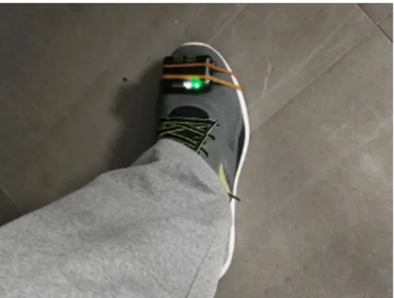
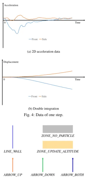
(2) Vol.2018-MBL-89 No.11 Vol.2018-ITS-75 No.11 2018/11/16. IPSJ SIG Technical Report. Fig. 2: Mount IMU on chest. Table 1: Specifications of our IMU. accelerometer gyroscope barometer size weight. range ±16g ±2000◦ /s 30 ∼ 110kPa. resolution 490µg 0.06◦ /s 0.18Pa 56 × 39 × 18mm 46g. sampling rate 400Hz 400Hz 25Hz. where the IMU is mounted and apply proper processes [6], [23]. In these body parts, the chest has fewest unexpected movements. In PDR based positioning systems, unexpected movements can introduce errors, decrease positioning accuracy and are difficult to handle. Therefore, the movement of chest is most simple and stable. In this paper, we propose an indoor positioning system with map matching using a chest mounted IMU. Our motivation is to create a body suit to support the work in multi-floor buildings. Since the movement of human chest is most simple and stable, we decided to mount the IMU on chest. The input data of our system is acceleration, angular velocity and barometric pressure. The specifications of our IMU*1 is listed in Table 1. To reduce the error accumulation on position and heading, we designed an efficient map matching algorithm based on particle filter. The components of our map are carefully designed, which can represent the building floor information clearly. With proposed algorithm implemented, our navigation system got second place in the IPIN 2018 Competition*2 Track 2, achieving mean error 5.2 meters after a 800 meters walking.. 2.. Related Work. Generally, a positioning system consists of three parts, step detection, step length estimation and map matching. In this section, we review the past works on these therr parts. The input data is a sequence of acceleration and angular velocity. Owing to the sensor noise, the computed displacement contains error. To avoid the error accumulation, step detection was proposed. For foot mounted IMU, Ojeda et al. proposed two empirical rules to separate steps [13], [14]. Madgwick et al. proposed a step detection algorithm based on filtering and thresh*1 *2. http://x-io.co.uk/ngimu/ http://ipin2018.ifsttar.fr/competition/about/. c 2018 Information Processing Society of Japan. olding, which only requires the norm of acceleration [4], [10]. For hand hold IMU, since the hand motion is complex and various, step detection is more difficult. To deal with this problem, Susi et al. proposed an adaptive algorithm which first recognize the motion type, then apply proper methods [19]. For head or chest mounted IMU, as implemented by Zhang et al., filtering and thresholding based algorithm is still a good choice [25]. Step length estimation is the process to compute the displacement of each step. The displacement consists of two parts, length and direction. Therefore, this process can be classified into two classes, computing the length and direction separately or not. Using a fixed step length works well in most situations. However, in some cases, this method may fail. To improve the accuracy, Weinberg et al. proposed an empirical equation to compute the step length for upper body mounted IMU [20]. The step direction can be computed from IMU pose. For foot mounted IMU, double integration can compute the length and direction together. However, simply applying double integration can not fit all motions. To settle this problem, Shin et al. proposed an adaptive step length estimation algorithm [18]. For hand hold IMU, Renaudin et al. proposed an adaptive algorithm based on motion mode classification [15]. Yan et al. proposed a regression model to compute the step displacement [23]. Utilizing the step detection and step length estimation can reduce the error on each step. However, the error on position still accumulates over time. Moreover, these processes cannot reduce the error on orientation. To solve these problems, particle filter based map matching algorithm has been proposed [16], [17], [22]. The particle filter is particularly good for dealing with non-linear and non-Gaussian estimation problems [2]. By implementing the particle filter based map matching algorithm to the navigation system, the positioning accuracy can be improved significantly. Davidson et al. showed how the particle filter improve the performance of indoor navigation [5]. By combining the backtracking particle filter with different level of 2D building plan detail, Widyawan et al. achieved high accuracy indoor navigation [9]. Bojja et al. proposed a 3D map matching algorithm in order to navigate in the 3D space [3].. 3.. Method. 3.1 Step Detection As shown in Figure 3, we use the filtering and thresholding to detect steps. First, as shown in Figure 3a, we compute the norm of 3D acceleration. To remove the noise, we apply a low pass filter to the norm. We define the interval from a peek to next peek as one step. The peek of norm corresponds to the moment that the foot hits ground, where the acceleration is maximum. The result of step detection is shown in Figure 3c. 3.2 Step Length Estimation To compute current position, we first transform the 3D acceleration data from sensor frame to the world frame. The transformation matrix is computed from the IMU pose. In our system, the IMU pose is updated by Madgwick’s algorithm [10]. In experiment, we found the displacement of one step can be computed by: 2.
(3) Vol.2018-MBL-89 No.11 Vol.2018-ITS-75 No.11 2018/11/16. IPSJ SIG Technical Report. Acceleration. Acceleration. 0. Time. Front. 0. Time. Side. (a) 2D acceleration data. (a) Norm of 3D acceleration Displacement Acceleration. 0. Time. Front. Side. (b) Double integration 0. Time. Fig. 4: Data of one step.. (b) Apply low pass filter Acceleration. ZONE_NO_PARTICLE. LINE_WALL. ZONE_UPDATE_ALTITUDE. 1 Step 0. ARROW_UP. Time. (c) Detected steps. ARROW_DOWN. ARROW_BOTH. Fig. 5: The components of our map.. Fig. 3: Process of step detection. " D=K·. a(t) dt dt. (1). where a(t) is the 3D acceleration of that step, K is a parameter which needs to be calibrated for each user. In this approach, the length and direction of one step can be computed at the same time. The 2D acceleration data (removed the up direction) of one step (moving forward) is shown in Figure 4a. By analyzing the data, we found that in one step, the decelerating phase is much more obvious than accelerating phase. Therefore, as shown in Figure 4b, the vector computed by double integrating the 2D acceleration is opposite to the forward direction. To transform it to correct direction and length, user parameter K is required. In our experiment, parameter K is in the range [−5.0, −3.0]. After calibration, the error on step length is in 10%. Note that the displacement on side is not zero. In normal, the steps are made by left foot and right foot alternately. Therefore, the upper body tends to left and right alternately. This is the reason that there is a side displacement in the step. Since the step made by left/right foot is usually followed with a step made by the other foot, the overall movement is forward. For the PDR systems based on upper body mounted IMU, the. c 2018 Information Processing Society of Japan. step direction is usually difficult to compute. Most systems requires the step direction keep the same with IMU heading, which makes the systems inconvenient to use. In our approach, since the step displacement is computed from transformed acceleration, it does not depend on IMU heading. Therefore, our system has no restriction on the step direction or IMU heading, which is more user-friendly. However, there is a drawback. In experiment, we found that using this approach can not update the altitude correctly. Thence, we decide to use the barometer instead. 3.3 Map Matching Our map matching algorithm is based on particle filter [16]. As shown in Figure 5, there are six components in our map. LINE WALL corresponds to the wall, which can not be crossed. In ZONE NO PART ICLE, the particles will be deleted. Also, new particles can not be produced in ZONE NO PART ICLE. Only in ZONE UPDAT E ALT IT UDE, the altitude will be updated. In our map, the stair, escalator and elevator correspond to the same component, ARROW. ARROW UP connects to upper floor, ARROW DOWN connects to lower floor, ARROW BOT H connects to both. Each particle has three parameters, current position Pi , current 3.
(4) Vol.2018-MBL-89 No.11 Vol.2018-ITS-75 No.11 2018/11/16. IPSJ SIG Technical Report. heading hi and scale si . Scale si is a scalar randomized from range [0.9, 1.1]. As discussed in Section 3.2, the error on step length is in 10%. Using this scale can cover the error of step length estimation. Final position P and heading h are computed by: P =. h=. n 1 X Pi · n i=1 n 1 X hi · n i=1. (2). (3). (a) Randomly selected particle. (b) Propose new particles. (c) Apply backtracking test. (d) Result. where n is the number of particles. For each particle, current position Pi is updated by: Pit+1 = Pit + R(D t · si , hi ). (4). where D t is the 2D displacement of current step, R(X, y) is a function which rotates vector X angle y. Hereafter, our system apply the collision detection to the particles. If the line from Pit to Pit+1 hits the LINE WALLs, the ith particle will be deleted. At last, our system produce new particles and wait for next step. The process of producing new particles is shown in Algorithm 1. The position of NewParticle is randomized from the circle with center Particle and radius Radius. The heading of NewParticle is randomized around the final heading h. The scale of NewParticle is randomized in the range [0.9, 1.1]. Fig. 6: Process of backtracking test. Blue arrows are recent steps. correct current position and restore the system. As discussed in Section 3.2, we use the barometer to update the altitude. Delta altitude ∆a can be computed by: ∆a = ∆p · −0.09m/Pa. Algorithm 1 Produce new particles ParticleNumberMax = 256 T ryT imeMax = 8 Radius = 3.0 ParticleNumber = n while ParticleNumber ≤ ParticleNumberMax: Particle = S electRandomParticle() T ryT ime = 1 while T ryT ime ≤ T ryT imeMax: NewParticle = ProposeNewParticle(Particle, Radius) if BacktrackingT est(NewParticle) == PAS S : AppendParticle(NewParticle) ParticleNumber = ParticleNumber + 1 break T ryT ime = T ryT ime + 1. When producing new particles, one problem is that the particles may be produced in impossible positions. This problem decreases the positioning accuracy, sometimes even crashes the map matching module. Inspired by the backtracking particle filter proposed by Widyawan et al. [9], we apply a backtracking test to new particles. In Figure 6, blue arrows corresponds to recent steps. First, new particles are randomly proposed around a randomly selected particle. As shown in Figure 6c, new particles go back recent steps and apply the collision detection. If the particle hits the walls, it will be deleted. As shown in Figure 6d, only particles passed this test are left. By applying the backtracking test, most new particles are produced around the correct position. This helps our system achieve higher accuracy. Moreover, this algorithm could also be used when the map matching failed to track the user. By applying the backtracking test to the randomly selected points around last estimated position, it is possible to find. c 2018 Information Processing Society of Japan. (5). where ∆p is the delta pressure. Even in indoor situation, the barometric pressure varies over time. To update the altitude correctly, we introduce ZONE UPDAT E ALT IT UDE to the map. Only in this zone, the altitude can be updated. Also, all ARROWs are defined in this zone. Since the user does not stay in this zone for a long time, this approach usually works well. When the delta altitude ∆a is closed to the floor height, our system will match current position to the export of the nearest ARROW and produce new particles. Every time the floor changes, the positioning error of our system can be reduced.. 4.. Evaluation. In this section, we present quantitative experiment results of our system. Basically, we followed the evaluation approach in IPIN 2018 Track 2. In each experiment, the user is asked to walk along a given route. Several key-points are set in the route before the experiment, the position of these key-points is known. The user is asked to stop at each key-point and record the estimated position output by our system. Error ei of the i-th key-point is defined by following equation: ei = D xy (Pgi , Pei ) + Dz (Pgi , Pei ) q D xy (Pgi , Pei ) = (Pgi .x − Pei .x)2 + (Pgi .y − Pei .y)2. (6). D xy (Pgi , Pei ) = |Pgi .z − Pei .z| · pz. (8). (7). where Pgi is the real position and Pei is the estimated position. Position P i has three elements, x, y and z. Element x and y are in meters, whereas element z is a scalar which represents current floor. pz is the penalty on floor, which is set to 15. 4.
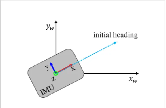
(5) Vol.2018-MBL-89 No.11 Vol.2018-ITS-75 No.11 2018/11/16. IPSJ SIG Technical Report. ݕ௪ initial heading. ݔ௪. Fig. 7: Calibrate the IMU pose with initial heading.. (a) Experiment route. Table 2: Experiment 1: the distribution of error travelled distance: 432.22m key-point number: 25 our system mean 0.78m median 0.51m 75th percent 0.76m standard deviation 0.92m. Table 3: Experiment 2: the distribution of error travelled distance: 792.49m key-point number: 70 our system mean 5.2m median 3.6m 75th percent 5.7m standard deviation 5.0m. In the experiment, initial position and heading are given to setup the system. The process of setup is: 1. open the IMU and launch our system software; 2. connect the IMU to the computer; 3. calibrate the IMU pose with initial heading (as shown in Figure 7); 4. attache the IMU on the user’s chest; 5. start tracking. In first experiment, we evaluate our system in the campus building with different configurations. As shown in Figure 8a, the user is asked to start at the pink point, go along the orange arrows, walk around the green route for three times and walk back to start point along the blue arrows. There is no open space in the route, the width of corridors is 2 − 3 meters. Therefore, we use 256 particles in this experiment. The travelled distance is 432.22 meters. The red points represent to key-points. The estimated routes of our system are shown as Figure 8c and Figure 8d. At the beginning of the route, the system without map matching still works well. However, the drift on heading is getting larger over time. Therefore, the result becomes worse. In our system with map matching, since the estimated position and heading are calibrated dynamically, the result is much more accurate and stable. The detailed results are shown in Figure 9 and Table 2. We also evaluated our system in the IPIN 2018 Competition Track 2. The competition is hold in a huge shopping mall which contains several open spaces. The evaluation route crosses three floors, consists of indoor and outdoor spaces. In indoor spaces, the width of corridors is 10 − 20 meters. Therefore, we use 512 particles in this experiment. During the competition, the shopping mall is crowded by customers. Our result is shown in Figure 10. In outdoor spaces, since the map matching can not work, our re-. c 2018 Information Processing Society of Japan. (b) Input map. (c) Result of our system, without map matching. (d) Result of our system, with map matching. Fig. 8: Experiment 1: evaluation on our system with different configurations. sult is not so good. When we went indoor, the result became acceptable, where error is generally less than 5 meters. As shown in Table 3, the mean error of our system is 5.2 meters. The IPIN competition evaluates the 75th percent error. Therefore, our final score is 5.7 meters, which is 0.2 meters worse than the champion. In 10 teams who participated in this track, we got the second place. The detail of the competition and our result can be found at http://ipin2018.ifsttar.fr/competition/about/. 5.
(6) Vol.2018-MBL-89 No.11 Vol.2018-ITS-75 No.11 2018/11/16. IPSJ SIG Technical Report. Error (m). [2]. 5 4.5 4. [3]. 3.5 3. [4]. 2.5 2 1.5 1. [5]. 0.5 0 1 2 3 4 5 6 7 8 9 10 11 12 13 14 15 16 17 18 19 20 21 22 23 24 25. Key ID. [6]. Fig. 9: Experiment 1: the error on each key-point. [7] Error (m) 25. [8] 20. [9]. 15. 10. [10]. 5. [11] 0 1 4 7 10 13 16 19 22 25 28 31 34 37 40 43 46 49 52 55 58 61 64 67 70. Key ID. [12]. Fig. 10: Experiment 2: the error on each key-point. [13]. 5.. Conclusion. In this paper, we proposed a novel indoor positioning system with map matching. In our system, the IMU is mounted on chest where the movement is most simple and stable. To reduce the error accumulation on position and heading, we designed an efficient map matching algorithm based on particle filter. Different from most existing algorithms, our map matching algorithm is designed for 3D navigation, which can be used in multi-floor buildings. With carefully designed components (wall, stair, escalator, elevator), our map can represent the building floor information clearly. With proposed algorithm implemented, our navigation system got second place in the IPIN 2018 Competition Track 2, achieving mean error 5.2 meters after a 800 meters walking. In our future work, we are improving the accuracy of the step length estimation. Also, as mentioned in our motivation, we are designing a body suit to support indoor work.. [14]. [15] [16] [17] [18] [19] [20] [21]. Acknowledgement A part of this work was supported by JSPS KAKENHI Grant Number JP18055433.. [22]. [23]. References [1]. Antigny, N., Servi`eres, M. and Renaudin, V.: Pedestrian Track Estimation with Handheld Monocular Camera and Inertial-Magnetic Sensor for Urban Augmented Reality, 2017 INTERNATIONAL CONFERENCE ON INDOOR POSITIONING AND INDOOR NAVIGATION. c 2018 Information Processing Society of Japan. [24] [25]. (2017). Arulampalam, M. S., Maskell, S., Gordon, N. and Clapp, T.: A tutorial on particle filters for online nonlinear/non-Gaussian Bayesian tracking, IEEE Transactions on signal processing, Vol. 50, No. 2, pp. 174–188 (2002). Bojja, J., Kirkko-Jaakkola, M., Collin, J. and Takala, J.: Indoor localization methods using dead reckoning and 3D map matching, Journal of Signal Processing Systems, Vol. 76, No. 3, pp. 301–312 (2014). Carberry, J., Hinchly, G., Buckerfield, J., Tayler, E., Burton, T., Madgwick, S. and Vaidyanathan, R.: Parametric design of an active ankle foot orthosis with passive compliance, Computer-Based Medical Systems (CBMS), 2011 24th International Symposium on, IEEE, pp. 1–6 (2011). Davidson, P., Collin, J. and Takala, J.: Application of particle filters for indoor positioning using floor plans, Ubiquitous Positioning Indoor Navigation and Location Based Service (UPINLBS), 2010, IEEE, pp. 1–4 (2010). Elhoushi, M., Georgy, J., Korenberg, M. and Noureldin, A.: Robust motion mode recognition for portable navigation independent on device usage, Position, Location and Navigation Symposium-PLANS 2014, 2014 IEEE/ION, IEEE, pp. 158–163 (2014). Finkenzeller, K.: RFID handbook: fundamentals and applications in contactless smart cards, radio frequency identification and near-field communication, John Wiley & Sons (2010). Jimenez, A. R., Seco, F., Prieto, C. and Guevara, J.: A comparison of pedestrian dead-reckoning algorithms using a low-cost MEMS IMU, Intelligent Signal Processing, 2009. WISP 2009. IEEE International Symposium on, IEEE, pp. 37–42 (2009). Klepal, M., Beauregard, S. et al.: A backtracking particle filter for fusing building plans with PDR displacement estimates, Positioning, Navigation and Communication, 2008. WPNC 2008. 5th Workshop on, IEEE, pp. 207–212 (2008). Madgwick, S. O., Harrison, A. J. and Vaidyanathan, R.: Estimation of IMU and MARG orientation using a gradient descent algorithm, Rehabilitation Robotics (ICORR), 2011 IEEE International Conference on, IEEE, pp. 1–7 (2011). Newman, N.: Apple iBeacon technology briefing, Journal of Direct, Data and Digital Marketing Practice, Vol. 15, No. 3, pp. 222–225 (2014). Ni, L. M., Liu, Y., Lau, Y. C. and Patil, A. P.: LANDMARC: indoor location sensing using active RFID, Pervasive Computing and Communications, 2003.(PerCom 2003). Proceedings of the First IEEE International Conference on, IEEE, pp. 407–415 (2003). Ojeda, L. and Borenstein, J.: Non-GPS navigation for security personnel and first responders, The Journal of Navigation, Vol. 60, No. 3, pp. 391–407 (2007). Ojeda, L. and Borenstein, J.: Personal dead-reckoning system for GPS-denied environments, Safety, Security and Rescue Robotics, 2007. SSRR 2007. IEEE International Workshop on, IEEE, pp. 1–6 (2007). Renaudin, V., Susi, M. and Lachapelle, G.: Step length estimation using handheld inertial sensors, Sensors, Vol. 12, No. 7, pp. 8507–8525 (2012). Ristic, B., Arulampalam, S. and Gordon, N.: Beyond the Kalman filter: Particle filters for tracking applications, Artech house (2003). Shin, S. H., Park, C. G. and Choi, S.: New Map-Matching Algorithm Using Virtual Track for Pedestrian Dead Reckoning, ETRI journal, Vol. 32, No. 6, pp. 891–900 (2010). Shin, S., Park, C., Kim, J., Hong, H. and Lee, J.: Adaptive step length estimation algorithm using low-cost MEMS inertial sensors, Sensors Applications Symposium, 2007. SAS’07. IEEE, IEEE, pp. 1–5 (2007). Susi, M., Renaudin, V. and Lachapelle, G.: Motion mode recognition and step detection algorithms for mobile phone users, Sensors, Vol. 13, No. 2, pp. 1539–1562 (2013). Weinberg, H.: Using the ADXL202 in pedometer and personal navigation applications, Analog Devices AN-602 application note, Vol. 2, No. 2, pp. 1–6 (2002). Woo, S., Jeong, S., Mok, E., Xia, L., Choi, C., Pyeon, M. and Heo, J.: Application of WiFi-based indoor positioning system for labor tracking at construction sites: A case study in Guangzhou MTR, Automation in Construction, Vol. 20, No. 1, pp. 3–13 (2011). Xiao, Z., Wen, H., Markham, A. and Trigoni, N.: Lightweight map matching for indoor localisation using conditional random fields, Proceedings of the 13th international symposium on Information processing in sensor networks, IEEE Press, pp. 131–142 (2014). Yan, H., Shan, Q. and Furukawa, Y.: RIDI: Robust IMU Double Integration, arXiv preprint arXiv:1712.09004 (2017). Yang, C. and Shao, H.-R.: WiFi-based indoor positioning, IEEE Communications Magazine, Vol. 53, No. 3, pp. 150–157 (2015). Zhang, Y., Hu, W., Xu, W., Wen, H. and Chou, C. T.: NaviGlass: Indoor Localisation Using Smart Glasses., EWSN, pp. 205–216 (2016).. 6.
(7)
図

+3

関連したドキュメント
Comparing the Gauss-Jordan-based algorithm and the algorithm presented in [5], which is based on the LU factorization of the Laplacian matrix, we note that despite the fact that
We start with some introductory materials to the over-relaxed η- proximal point algorithm based on the notion of maximal η-monotonicity, and recall some investigations on
By an inverse problem we mean the problem of parameter identification, that means we try to determine some of the unknown values of the model parameters according to measurements in
We proposed an additive Schwarz method based on an overlapping domain decomposition for total variation minimization.. Contrary to the existing work [10], we showed that our method
These authors make the following objection to the classical Cahn-Hilliard theory: it does not seem to arise from an exact macroscopic description of microscopic models of
These authors make the following objection to the classical Cahn-Hilliard theory: it does not seem to arise from an exact macroscopic description of microscopic models of
The aim of this work is to prove the uniform boundedness and the existence of global solutions for Gierer-Meinhardt model of three substance described by reaction-diffusion
Here general is with respect to the real analytic Zariski topology and the dimension of a fiber is well-defined since the fiber is covered by a countable union of real analytic
