Kansai Photon Science Institute
Quantum Beam Science Research Directorate National Institutes for
Quantum and Radiological Science and Technology
ANNUAL REPORT 2018
QST-M-20
Contents
Preface 1
Activities of KPSI 3
User Facilities 7
Research Highlights 13
Publication List 55
The Kids’ Science Museum of Photons 65
Appendix 79
はじめに
本年報では、関西光科学研究所(以下、関西研)において 2018 年度に実施した研究開発の主だった成果を紹 介しています。関西研は国立研究開発法人量子科学技術研究開発機構(以下、量研)の研究開発拠点であり、
けいはんな学研都市にある京都府木津地区と兵庫県播磨地区の2か所に研究サイトを持っています。そこでは、研究 系職員約 80 名及びそれを支える技術系・事務系スタッフを含めて総勢約 150 名のスタッフが、量研における関西研の ミッションである「レーザーや放射光による光科学技術の研究開発」を推進しています。木津地区では、世界トップレベル の高強度レーザー技術を基盤としたレーザー加速やX線発生等のレーザー駆動の新しい放射線源開発、レーザーの短 パルス性を活かした超高速計測技術開発、そして放射線影響や創薬に資する量子生命科学の最先端の研究開発を 実施しています。また、播磨地区では、大型放射光施設 SPring-8 の 2 本の専用ビームラインと計算機シミュレーション を活用することで、新しい放射光X線利用技術開発と物質材料科学の最先端研究を展開しています。
量研関西研として3年が経ち、新しい組織の中で優れた研究成果が生まれ始めています。木津地区のレーザー科学 分野においては、J-KAREN レーザーの光学素子の配置を見直すことによるパルスコントラストの改善や、レーザー加速に よる GeV 級の準単色電子ビーム生成やプラズマからの高次高調波を用いた極短パルスX線発生に成功するなどの成 果を挙げるとともに、生命科学分野においては、遺伝子の転写制御メカニズムにおける DNA の物理化学的な役割を解 明する等の新たな知見が生まれています。また、播磨地区においても、放射光X線を用いた鉱物マガダイトの機能発現 機構の解明やX線自由電子レーザーSACLA を用いた世界最短波長の超蛍光の観測など、数多くの優れた成果を挙 げています。さらに、光技術の社会実装の観点からは、非侵襲血糖値測定技術やレーザーによるトンネル検査技術の 実用化に向けた取組を引き続き行っています。
関西研は、「光」を通じた我が国の量子科学技術の発展とイノベーション戦略に貢献する開かれた研究拠点としての 役割を果たすべく、今後とも職員一同、より一層努力してまいります。皆様のご理解・ご協力を宜しくお願い申し上げま す。
2019 年 4 月 8 日 関西光科学研究所 所長 河内 哲哉
Preface
This annual report from Kansai Photon Science Institute (KPSI) provides highlights of the scientific and technical researches that were conducted over the 2018 fiscal year.
KPSI was reconstituted in April 2016 as one of the research and development (R&D) bases of National Institutes for Quantum and Radiological Science and Technology (QST). At KPSI's two R&D sites, the Kizu site in Keihanna Science City in Kyoto Prefecture and the Harima site in Hyogo Prefecture, there are about 150 staff, comprising around 80 researchers and the technical and administrative staff who support them. We promote the R&D of optical science and technology using lasers and synchrotron-radiation X-rays, which is the mission of KPSI in QST. At the Kizu site, we are conducting state-of-the-art research for developing new-type laser-driven radiation sources such as laser accelerated particle beam and ultrashort X-rays based upon world-leading top-class high-intensity laser technology, ultrafast measurement methodology using ultrashort pulse technology, and quantum life science that helps us understand radiation effects and develop new medicines. At the Harima site, using two contract beamlines of SPring-8 and computer simulation, we are developing new technology to utilize synchrotron radiation X-rays and carrying out state-of-the-art research in material science.
Three years have passed since the restart of KPSI in QST, and several outstanding results are being produced.
In the laser science field at the Kizu site, the pulse contrast of the J-KAREN laser is substantially improved by reviewing the arrangement of the optical elements, and we have succeeded in generating GeV class quasi-monochromatic electron beam by laser acceleration and ultrashort X-rays generation using higher-order harmonics from relativistic plasma. In the field of the life science, new findings emerged such as elucidating the physicochemical role of DNA in the transcriptional controle mechanism of genes. At the Harima site, we also obtained several excellent results such as discovering the functional expression mechanism of mineral magadiite using synchrotron radiation X-rays and the observation of the shortest wavelength super fluorescence using the X-ray free electron laser SACLA. In addition, regarding the social implementation of optical technology, we are making efforts toward practical application of non-invasive blood glucose measurement and laser based tunnel inspection technology.
KPSI will continue to fulfill our role as an open research center of "science of light" and will contribute to quantum science and technology and the strategy for innovation in Japan. We appreciate your understanding and cooperation.
8
thApril, 2019
Director General of KPSI
Tetsuya KAWACHI
Activities of KPSI
関西光科学研究所の主な動き
シンポジウム・研究会等の開催
5
月8
日~9日 「光・量子ビーム科学合同シンポジウム2018」
関西研多目的ホール棟(京都府木津川市) 大阪大学と量研との間 で締結された包括協定に基づき、関西研と大阪大学レーザー科学 研究所の連携協力体制をより強固なものにし、光・量子ビーム科学 分野の研究開発を加速することを目的として、合同シンポジウム を開催しました。
6
月6
日~8日 「第34
回化学反応討論会」 関西研多 目的ホール棟(京都府木津川市) 化学反応速度論および動 力学に関連する幅広い分野の研究者が一堂に会し、励起状態 の生成と緩和を含む化学反応に関する新しい知見、それらの 応用研究に関する最先端の実験および理論について討論を 行いました。招待講演、口頭発表、ポスター発表を通して、3
日間に渡り討論を行い、展示企業9
社を含む約150
名の 方々が参加しました。11
月26
日~29日 「The 8thAsian Summer School &
Symposium on Laser Plasma Acceleration and Radiation
(ASSS-8)」関西研多目的ホール棟(京都府木津川市)
、奈良春日野国際フォーラム“甍”(奈良県奈良市)
ASSS
は51
名(講師10
名含む。中国、韓国、ネパール、日本、スペイ ン、イギリス、ロシア、チェコ、ドイツ、米国)の参加者で の開催となりました。3日目、4日目は第2
回QST
国際シ ンポジウムと合同で行いました。11
月27
日 「ドイツHZDR・阪大 ILE・KPSI-QST
第2
回ワークショップ」関西研木津地区(京都府木津川市)HZDR
(ドイツ)および大阪大学レーザー科学研究所(阪大ILE)と合同で高エネルギー密度科学や高強度レーザーに関
するワークショップを開催し、情報交換を行いました。11
月28
日~29日 「第2
回QST
国際シンポジウム」奈良春日野国際フォーラム“甍”(奈良県奈良 市) 高強度レーザーが切り拓く新たな光・量子科学技術をテーマに、第2
回QST
国際シンポジウムを 開催し、251
名の参加者が集いました。高強度レーザー開発とその応用に関わる幅広い研究分野で活躍し ている国内外の研究者を招待し、高強度レーザーが切り拓く光・量子科学技術の最先端研究に係るQST
国際シンポジウムを開催したことで、世界の潮流をとらえるとともに、QST
のプレゼンスを高めること ができました。12
月6
日~7日 「レーザー応用技術産学官連携成果報告会」福井大学附属国際原子力工学研究所(福 井県敦賀市) 原子力機構と量研の間で平成28
年度に締結された「レーザー技術の開発及び普及の推進」に関する覚書に基づき、レーザー応用技術・産学官連携成果に関する報告会を開催しました。
3
月1
日 「QST放射光科学シンポジウム2019/微細構造解析プラットフォーム第 3
回放射光利用研 究セミナー」大型放射光施設SPring-8 放射光普及棟大会議室(兵庫県佐用町) 関西研放射光科学研
究センター、文部科学省ナノテクノロジープラットフォームQST
微細構造解析プラットフォームの主催 で、QST放射光科学シンポジウムを開催しました。センターの職員のみならず、外部の第一線の共同研 究者も交えて、先端的放射光利用技術の開発、物質・材料の研究、次世代放射光施設で期待される軟X
線 放射光を利用した研究などについての講演が行なわれ、ナノテクノロジープラットフォーム事業の推進 に資する講演会となりました。SPring-8 のイベント
4
月29
日に第26
回SPring-8&SACLA
施設公開が開催さ れ、関西研は専用ビームライン(BL11XUとBL14B1)を公開
し、講義授業及び展示実験等を行いました。今年は絶好の好天 に恵まれ、理研の広報も行き届き、過去最高記録を大幅に更新する
10,672
名もの参加者がありました。7
月8
日~11日に第18
回SPring-8
夏の学校が開催され、関 西研は11
の主催団体の一つとして貢献しました。次世代の放 射光利用研究者の発掘と育成を目的として、関西研では、主と してビームライン14B1
における実習(放射光を利用した高温 高圧合成)を実施しました。関西光科学研究所(木津地区)施設公開
10
月28
日に関西光科学研究所(木津地区)の施設公開を開 催しました。昨年度は台風の影響でやむを得ず中止となりまし たが、今年度は天候にも恵まれ1,104
名もの方々にお越しいた だきました。世界トップクラスの高強度レーザー施設の見学 や、光の実験ショー、工作教室などに加え、高崎量子応用研究 所からのブース出展もあり、ご来場いただいた皆様にはご好評 をいただきました。レーザー打音検査装置の社会実装試験
内閣府が主導する戦略的イノベーションプログラム(SIP)の支 援を受けて、トンネルコンクリートの内側の欠陥を遠隔・高速に検 査する技術の共同開発の一環として、社会実装試験を行いました。
今年度は、学研都市推進機構からのご紹介で、
5
月に奈良市、6
月 に大阪府の道路トンネルを試験場として提供して頂き、実際のト ンネル現場での実証試験を行いました。また12
月には、関西研から
400km
離れた静岡県の尾崎トンネルまで自走で移動しての実証試験に成功しました。梅雨の最中の日々刻々と変化する天候の中で装置を稼働させた経験や、遠距離 移動を伴うレーザー打音検査装置の運用試験を実施できたことは、実用化への大きな自信となりました。
木津地区の主な出展イベント
2018
年度も積極的にアウトリーチ活動を実施しました。きっづ光 科学館ふぉとんの年間来場者は昨年度を上回り48,000
人を達成しま した。4
月8
日「第41
回花と緑の見学会」出展 高崎量子応用研究所(群 馬県高崎市)7
月28
日~29日「青少年のための科学の祭典2018
全国大会」出展 科学技術館(東京都千代田区)8
月2
日~3日「夏休み2018
宿題自由研究大作戦」出展 インテッ クス大阪(大阪府大阪市住之江区)10
月4
日~5日「京都スマートシティエキスポ2018」出展 けい
はんなオープンイノベーションセンター(京都府相楽郡精華町)10
月4
日~5日「第13
回けいはんなビジネスメッセ2018」出展
けいはんなプラザ(京都府相楽郡精華町)10
月25
日~27日「けいはんな情報通信フェア2018」出展 けい
はんなプラザ(京都府相楽郡精華町)受賞ラッシュ
平成
30
年春の褒章 「紫綬褒章」 小池雅人客員研究員(光量子科学研究部)平成
30
年秋の叙勲 「瑞宝中綬章」 加藤義章先生(元関西研所長)2018
年ノーベル物理学賞CPA(チャープドパルス増幅)技術 関西研設立に際しご助言頂くなど
関西研と関わりの深いGérard Mourou(ジェラルド
ムルー)先生2018
年チャンドラセカール賞 田島俊樹先生(元関西研所長)アメリカ物理学会
2019
年 Robert R. Wilson賞 田島俊樹先生(元関西研所長)User Facilities
主要な施設・装置
木津地区
〇J-KARENレーザー装置
【装置概要】
世界トップクラスの極短パルス超高強度レーザーです。30J のレー ザーエネルギーを
30
フェムト秒(1フェムトは1000
兆分の1)の時
間に閉じ込めることにより1000
兆ワットの超高強度を実現します。(右の写真は強力な励起レーザーの光で緑色に光っています。)
【装置性能】
・照射エネルギー:30 J/pulse
・コントラスト比:10-12
・波長:800 nm
・繰り返し:0.1 Hz
・パルス幅:30 フェムト秒
・集光強度:1022
W/cm
2【主要な研究課題】
レーザーの高度化技術の開発、イオンおよび電子のレーザー加速技術の開発、高エネルギーコヒーレ ント
X
線の発生等〇X線レーザー実験装置
【装置概要】
強力なレーザーで作ったプラズマを使って発振する
X
線のレーザー です。目に見える光に比べて発振波長が短く、さらにほんの一瞬の短 い間しか光らないという特徴を生かして、固体表面で起こる物性現象 の変化の様子の観察等に利用しています。【装置性能】
・照射エネルギー:1 μJ/pulse
・波長:13.9 nm
・繰り返し:0.1 Hz
・パルス幅:約
10
ピコ秒【主要な研究課題】
軟
X
線光学素子の評価、フェムト秒レーザーアブレーションの機構解明〇QUADRA-Tレーザーシステム
【装置概要】
1
秒間に1000
発のレーザーパルスが繰り出せる高平均出力ピコ秒パル スレーザーです。中心周波数0.3THz
の高強度テラヘルツパルスを発生 することが可能です。【装置性能】
・照射エネルギー:10 mJ/pulse
・波長:1030 nm
・繰り返し:1 kHz
・パルス幅:約
1
ピコ秒【主要な研究課題】
高繰り返し高出力レーザー(パラメトリック増幅器等)の開発、高強度テラヘルツ光源の開発
播磨地区
播磨地区では大型放射光施設
SPring-8
に2
本のQST
専用ビームラインを設置しているほか、日本原 子力研究開発機構(JAEA)の専用ビームラインにも複数の放射光専用実験装置を常設しています。一方 で、QST専用ビームラインにも、JAEAの専用実験装置が常設されています。〇BL11XU(QST極限量子ダイナミクスⅠビームライン)
【装置概要】
SPring-8
標準の真空封止アンジュレータを光源とし、マルチ結晶交換システムを装備することで、広範囲のエネルギー領域の高輝度放射光
X
線を高効率に利用できるビームラインです。【装置性能】
・光源:真空封止アンジュレータ
・エネルギー領域:6~70 keV
・分光結晶:Si(111)、Si(311)
・実験装置:放射光メスバウアー分光装置、共鳴非弾性
X
線散乱装置、及び表面X
線回折計1.
放射光メスバウアー分光装置57
Fe、
61Ni
等のメスバウアー核種を対象とした放射光メスバウアー分光が 可能で、物質の電子、磁気状態から格子振動状態に関する情報などを得るこ とができます。2.
共鳴非弾性X
線散乱装置2m
長アームに搭載した球面湾曲型集光式アナライザー結晶による背面反 射を用いることで、高分解能のX
線分光を行い、散乱光の方位や入射光との エネルギー差から、運動量移行を伴う固体内素励起が観察できます。3.
表面X
線回折計分子線エピタキシー(MBE)チェンバーを搭載した表面構造解析用装置 で、窒化物を含む半導体結晶などの成長過程を、
X
線回折法を用いてその場 観察・リアルタイム観察することができます。【主要な研究課題】
金属薄膜の原子層単位での磁性探査、白金系燃料電池触媒の電子状態解析、半 導体量子ドットや半導体多層膜の成長過程のリアルタイム解析
〇BL14B1(QST極限量子ダイナミクスⅡビームライン)
【装置概要】
偏向電磁石を光源とすることで、連続スペクトルを持つ白色
X
線や高エネルギーの単色X
線が利用 可能なビームラインです。全反射ミラーや分光結晶の曲げ機構によって、試料位置への集光が可能とな っています。【装置性能】
・光源:偏向電磁石
・エネルギー領域:白色
X
線(5~150 keV)、単色X
線(5~90 keV)・実験装置:高温高圧プレス装置、分散型
XAFS
測定装置(JAEA)及びκ(カッパー)型回折計(JAEA)1.
高温高圧プレス装置高温高圧の条件下にある試料を、白色
X
線を用いたエネルギー分散型X
線回折 法やラジオグラフィー法、単色X
線を用いたXAFS(X
線吸収微細構造)法や角度 分散型X
線回折法によって調べることができます。【主要な研究課題】
高圧下での金属水素化物形成過程のその場観察
〇BL22XU(JAEA専用ビームライン)における放射光専用実験装置
1.
単色X
線実験用高温高圧プレス装置(JAEABL22XU)
高温高圧下(到達圧力
10 GPa(10
万気圧)、到達温度2000 K 程度)
の
X
線回折測定やX
線吸収法を用いた密度測定、室温、1 MPa
未満の水素 ガス雰囲気中でのその場X
線回折観察、時分割X
線回折測定が可能な装置 です。2.
ダイヤモンドアンビルセル回折計(JAEABL22XU)
大型イメージングプレート検出器と高エネルギーX 線を利用することに より、高圧下での単結晶
X
線回折及び粉末X
線回折実験、X線全散乱測定 及び原子二体分布関数(PDF)解析が可能な装置です。3.
大型X
線回折計共鳴
X
線散乱による電子軌道状態の観測、スペックル回折によるドメイ ン構造の研究、応力・歪み分布測定などの回折マッピングなど多目的に利 用する四軸回折計です。【主要な研究課題】
水素貯蔵合金の水素吸蔵過程の時分割その場
X
線回折測定、負の熱膨張材料、超伝導体、f
電子系化 合物、コヒーレントX
線を利用したスペックル散乱によるナノドメイン観察。応力・歪みの3
次元分 布測定、等施設の稼働実績
〇木津地区
実施課題件数
装置名称 独自研究 受託研究 共同研究 施設共用
J-KAREN
レーザー装置2 2 0 2
X
線レーザー実験装置0 1 5 1
QUADRA-T
レーザーシステム1 0 0 0
kHz
チタンサファイアレーザー3 0 4 0
X
線回折装置1 0 1 0
軟
X
線平面結像型回折格子0 0 1 0
〇播磨地区
2018
年度のSPring-8
蓄積リングの運転時間は約5230
時間で、放射光利用時間はそのうちの約4600
時間でした。量研、原子力機構とも専用ビームラインでは
10~20%弱程度の調整時間を除き、放射光利
用時間で独自研究や受託研究、外部利用者への施設共用と研究支援を行っています。実施課題件数
ビームライン 独自研究 受託研究 共同研究 施設共用
BL11XU 8 0 11 20
BL14B1 12 0 1 7
BL22XU 5 0 5 12
利用日数
ビームライン 独自研究 受託研究 共同研究 施設共用
BL11XU 79 0 78 53
BL14B1 56 0 3 19
BL22XU 35 0 34 32
施設の利用状況
〇木津地区
〇播磨地区
J-KAREN
レーザー装置(合計ビームタイム:
1612
時間)その他装置(木津地区)
(合計ビームタイム:1565時間)
QUADRA-T
レーザー装置(合計ビームタイム:178時間)
X
線レーザー実験装置(合計ビームタイム:
1597
時間)内部利用, 67%
メンテナンス, 28%
内部利用, 36%
内部利用, 68%
内部利用, 100%
メンテナンス, 31%
メンテナンス, 4%
共同研究, 30%
共同研究, 28%
施設共用, 5% 施設共用, 3%
Research Highlights
R & D for Advanced Photon Research Kiminori Kondo (Director)
Department of Advanced Photon Research
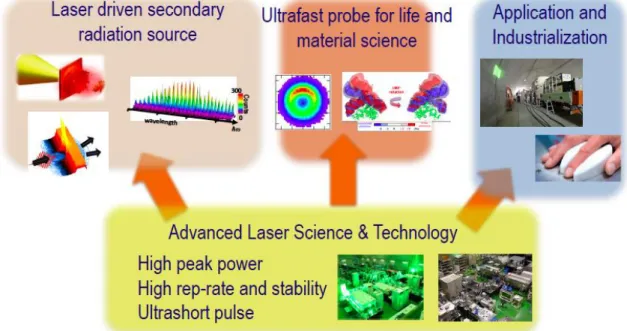
In the department of Advanced Photon Research, the base of the research is the science and technology of advanced lasers. In particular, high-peak-power laser technology, high-repetition- rate and high-stability laser technology, and ultrashort-pulse technology are the most important. We develop these technologies in-house and apply them to various objects. The largest laser system in KPSI is the Petawatt (PW)-class high- peak-power laser J-KAREN-P. This system has been upgraded since obtaining the supplementary budget in FY2012. The long commissioning operation term was completed in the last fiscal year. Therefore, from this fiscal year, not only internal users in KPSI, but external users have also started to use the system in PW-class operation mode. The restart of the external user mode for J-KAREN-P should be emphasized here. The extreme focused intensity of 10
22W/cm
2on target with extremely high-contrast suppression of the proceeding optical component to the main pulse is now available. This extreme status of our high-power laser infrastructure is maintained by the laser facility operation office, advanced laser group, and high-intensity laser science group. In particular, the advanced laser group not only maintains J-KAREN-P to deliver the laser pulse with the best condition, but also develops and introduces new technology to maintain the condition of J-KAREN-P as world-leading class. High-intensity laser science group mainly studies laser-driven ion acceleration, laser electron acceleration, and relativistic high-order harmonic generation with J-KAREN-P in KPSI.
One of the most important applications is the development of a laser-driven secondary radiation source. An extremely high optical filed can be formed with focusing extremely high peak
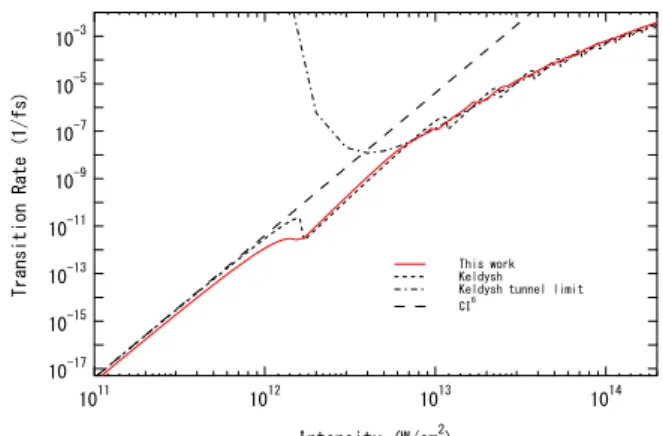
power to an ultimately small spot size. Atoms and molecules exposed to this extremely high field are immediately ionized by field ionization. Actually, the corresponding optical intensity to the atomic unit is only 3 × 10
16W/cm
2, which is much lower than that to be generated with J-KAREN-P. The generated free electrons move along the extremely high optical filed, then the ultra-relativistic quiver motion is induced. These energetic quivering electrons induce the generation of various secondary radiations. This means that there is a possibility of a compact energetic quantum beam source without conventional accelerator technology. If this technology is established and applied to various fields, a type of destructive innovation could occur. For example, one of the most important applications of a laser-driven secondary radiation source is the application to Quantum Scalpel, which is a new-generation heavy-ion cancer therapy machine planned to be developed by 8 years from now. Quantum Scalpel is the one of the main projects in QST. The injector part of Quantum Scalpel is based on the laser-driven carbon accelerator.
The JST-MIRAI R & D program (large-scale type) started in Nov.
2017. The aim of this program is show a proof of concept. Not only ion accelerator, but laser plasma electron accelerator is also under development in KPSI, with this MIRAI program by JST and ImPACT program by the cabinet. Moreover, not only charged particle acceleration, but X-rays are also generated with ultrashort high-peak-power lasers. Burst intensification by singularity emitting radiation (BISER) is the new laser-driven coherent X- ray generation scheme, which has been invented by KPSI.
Usually high-order harmonics are generated from the outermost bound electrons in atomic and molecular systems in a sufficiently high optical field. Therefore, the quiver energy is limited even
Fig. 1 Research and development of department of Advanced Photon Research
with using an IR pump laser for taking higher quiver energy in the same interaction intensity. However, BISER is emitted by the oscillation of a high-density electron bunch formed by a laser wakefield. Then, in principle, there is no limit on the quiver energy of electron bunch oscillation. There is a possibility of a keV-scale coherent X-ray source without using a gigantic linac like such as SACLA. These secondary radiation sources driven by ultrashort high-peak-power lasers are under research mainly by the high-intensity laser science group and the advanced laser group.
The next important application of our advanced laser science and technology is an ultrafast probe for life and material science.
In particular, for material science, not only an ultrashort probe, but THz radiation is also developed, mainly in the ultrafast dynamics group. Until the last fiscal year, the C-Phost project has been performed by the ultrafast dynamics group. Strong THz radiation is generated with a kHz 10-mJ ps laser system, QUADRA-T. These radiation and laser systems are used for various ultrafast dynamics research. For life science applications, a bright and stable short pulse laser system has been developed and applied to the two-photon microscope for observing the neuron dynamics in mouse brain at NIRS. This research began to demonstrate one of the featured results by the unification of NIRS and JAEA two years ago. In this fiscal year, a deeper part was successfully obtained with the developed bright laser system than that with the commercially based system. Recently, the ultrashort probe could be upgraded to the attosecond regime to start attosecond science in KPSI. Not only attosecond science, but the related study of CPS laser fabrication also has been started. These studies are supported by the Q-LEAP program, which has started from this fiscal year and could continue for 10 years. This project will be studied by the ultrafast dynamics group and X-ray laser group. The X-ray laser group studies the interaction between intense X-rays and solid materials with the laser–plasma-based X-ray laser at KPSI and SXFEL at SACLA. The intense X-ray fabrication technology is an important fine structure fabrication technology, which has advanced to current laser fabrication technology. The repetition rate of the present X-ray laser system in KPSI is only 0.1 Hz, whereas it is 60 Hz in SACLA. Then, the X-ray laser group will shut down the present X-ray laser system and will upgrade it to a 10 to 100-Hz system based on a Ti:sapphire laser technique in the near future.
In a sense, the most important application of our advanced laser science and technology is industrialization. In fact, this fiscal year is the final fiscal year for the SIP program by the cabinet for the development of nondestructive tunnel inspection technology. This technology is tried to apply to commercial technology for making the venture company. One of the key technologies of the nondestructive tunnel inspection technology is the high-average-power high-repetition-rate intense laser technology. This technology is used for hitting the inner surface of the concrete tunnel to induce an acoustic wave inside the wall.
To induce an acoustic wave of sufficient amplitude, a 5-J per pulse with 50-Hz repetition rate system has been developed and successfully loaded on an inspection vehicle. This system has been successfully demonstrated in a real tunnel. The impression of the general people was very high, and there was much press coverage related to this technology in this fiscal year. This technology is closely related to the development of high-average- power high-peak-power laser systems, which could be used in the laser-driven carbon ion injector in Quantum Scalpel.
In this annual report, some topical studies are introduced from recent results published in several journals. From the high- intensity laser science group, the physics related to the flying
mirror are shown by Dr. Koga. Dr. Kai reports on a unique diagnostic study on electron bunches in a laser wakefield. This study is performed under the ImPACT program which will finish within this fiscal year. From the advanced laser group, Dr.
Sagisaka reports on high-order harmonics and proton generation from a thin foil irradiated by an extremely high optical field. Dr.
Fukuda shows his unique laser acceleration study of pure proton
acceleration using a hydrogen cluster target. From the X-ray laser
group, Dr. Imazono reports a flat-field grating spectrometer for
the tender X-ray region. Dr. Ishino discusses the damage
generation with intense picosecond X-rays. From the ultrafast
dynamics group, Dr. Otobe shows an analytical model of electron
excitation in dielectrics in high field. Dr. Itakura explains his
unique ultrafast measurement scheme using plasma reflection.
Relativistic Flying Mirrors Generating Upshifted Higher Harmonic Generation
James K. Koga
High-Intensity Laser Science Group, Department of Advanced Photon Research
Horseshoe bats use echolocation to determine their position and because their emitters (nose) and receivers (ears) are both moving, they experience the double Doppler effect [1]. Figure 1 shows a schematic of this. They also dynamically lower their emitting frequency to keep the reflected signal within a frequency
range [1]. This double Doppler effect can also occur with light.
In his paper on special relativity, Einstein described the upshift of electromagnetic radiation from a relativistically moving mirror [2]. However, a large amount of energy is necessary to accelerate a macroscopic object to relativistic velocities, such as shown in the NASA starlight program [3]. Because lasers propagating in plasma at nearly the speed of light can generate plasma waves, it was proposed to use breaking plasma waves as relativistic mirrors to reflect, compress, and upshift laser light [4]. This concept has been shown to work theoretically [4], numerically [5], and experimentally [6–9] (see also review [10]). However, until now the laser pulse reflecting off the relativistic mirror has been chosen to be of sufficiently low intensity that the energy of the reflected pulse is far below the energy stored in the wake wave, such that the mirror is not significantly perturbed [11]. In this work we considered strong laser pulses and how they would reflect off of relativistically moving plasma waves [12]. We were motivated by the fact that obtaining and using high-intensity light with high frequencies and short wavelengths is of interest not only for applications, but also from a fundamental point of view [13,14].
In order to investigate the possibility of using strong laser pulses reflecting off relativistic flying mirrors, we performed numerical calculations via one-dimensional particle-in-cell (PIC) simulations using the code EPOCH [15]. The simulations consisted of two counter-propagating laser pulses colliding in an underdense plasma. One high-intensity laser was used to generate
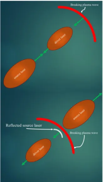
the breaking plasma wave (driver) and the other laser was used to reflect off of the relativistic flying mirror (source). Owing to the large upshift factor, the source laser had a wavelength longer than the driver pulse to allow resolution of the expected short wavelength reflected radiation within reasonable simulation sizes [12]. We found that source pulses with intensities even near the relativistic regime could be reflected off the relativistic flying mirrors [12]. In the best case of the considered simulations, harmonics of the upshifted source pulse were observed and wavelengths up to ~160 times shorter than the original source pulse were generated [12]. Figure 2 shows a schematic of the interaction, in which the driver laser and source laser collide in an underdense plasma and a portion of the source pulse is reflected, upshifted, and compressed by the breaking plasma wave, i.e., the relativistic flying mirror. The details can be found in [12].
In the future, with higher-dimensional scenarios, we will investigate the focusing of the reflected source pulses and will consider using them for electron–positron pair creation with several focused laser pulses [16].
Acknowledgments
This work was performed with Sergei V. Bulanov, Timur Zh.
Esirkepov, Masaki Kando, Stepan S. Bulanov, and Alexander S.
Pirozhkov. This work was supported by JSPS KAKENHI Grant Number JP16K05639 and by the project High Field Initiative (CZ.02.1.01/0.0/0.0/15_003/0000449) from the European Regional Development Fund. SSB acknowledges support from the Office of Science of the US DOE under Contract No. DE- AC02-05CH11231. The simulations were performed on the “SGI ICE X” supercomputer at the Tokai Research and Development Center of the Japan Atomic Energy Agency.
References
1. Biophysics, edited by W. Hoppe, W. Lohmann, H. Markl, and H. Ziegler, Springer-Verlag, Berlin 1983.
2. A. Einstein, Ann. Phys., Lpz. 322 891 (1905).
3. N. Kulkarni, P. Lubin, and Q. Zhang, The Astronomical Journal 155, 155 (2018).
4. S. V. Bulanov, I. N. Inovenkov, V. I. Kirsanov, N. M.
Naumova and A. S. Sakharov, Sov. Phys.—Lebedev Inst. Rep.
6, 9 (1991).
5. S. V. Bulanov, T. Zh. Esirkepov and T. Tajima, Phys. Rev. Lett.
91, 085001 (2003).
6. M. Kando, et al., Phys. Rev. Lett. 99, 135001 (2007).
7. A. S. Pirozhkov, et al., Phys. Plasmas 14, 123106 (2007).
8. M. Kando, et al., Phys. Rev. Lett. 103, 235003 (2009).
9. A. S. Pirozhkov, et al., AIP Conf. Proc. 1153, 274 (2009).
10. S. V. Bulanov, T. Zh. Esirkepov, M. Kando, A. S. Pirozhkov and N. N. Rosanov, Phys. Usp. 56, 429 (2013).
11. A. S. Pirozhkov, S. V. Bulanov, T. Zh. Esirkepov, A. Sagisaka,
T. Tajima and H. Daido, Intensity Scalings of Attosecond
Figure 1. Bat using the double Doppler effect
Pulse Generation by the Relativistic-irradiance Laser Pulses, in Ultrafast Optics V (Berlin: Springer) 265 (2007).
12. J. K. Koga, S. V. Bulanov, T. Zh. Esirkepov, M. Kando, S. S.
Bulanov and A. S. Pirozhkov, Plasma Phys. Control. Fusion 60, 074007 (2018).
13. T. Yamaji, et al., Phys. Lett. B 763, 454 (2016).
14. J. K. Koga and T. Hayakawa, Phys. Rev. Lett. 118, 20480 (2017).
15. T. D. Arber, et al., Plasma Phys. Control. Fusion 57 113001 (2015).
16. S. V. Bulanov, et al., Nucl. Instrum. Methods Phys. Res. A 660, 31 (2011).
Figure 2. Driver laser creating breaking plasma wave,
relativistic flying mirror, and counter-propagating source
laser in a background underdense plasma (upper figure). Part
of the source laser is reflected off the breaking plasma wave
(relativistic flying mirror), upshifted, and compressed (lower
figure).
Introducing the electro-optic spatial decoding technique into laser wakefield acceleration
Kai Huang and Masaki Kando
High Intensity Laser Science Group, Department of Advanced Photon Research
Laser wakefield acceleration (LWFA) [1] has been studied intensively owing to its inherent ultrashort and ultrahigh- acceleration gradient characteristics. By using an ultrashort and ultra-intense laser pulse (10
18W/cm
2) from chirped pulse amplification (CPA) [2], a large-amplitude plasma wave can be produced in underdense plasma, allowing the electron bunch to be accelerated to GeV range over centimeter-scale distances.
Secondary X-ray sources from such electron bunches by undulators [3] or betatron [4] oscillations are considered to have potential applications in the ultrafast X-ray pump–probe studies.
Because X-ray photons are emitted by electron bunches, the emission timing and pulse durations of the X-ray sources are directly determined by the temporal characteristics of the electron bunches. The electrons from LWFA are always assumed to be injected into the first bucket just after the drive laser pulse. Thus,
“jitter-free” or relatively small jitter were always considered to be the merits of LWFA. Yet, the emission timings of the electrons have to date never been experimentally measured. For a plasma wave in linear mode, the ambient electrons could be trapped randomly into a certain wave bucket. The possibility that electron bunches could have jitter cannot be ignored.
The durations of the electron bunches from LWFA have been determined by the analyzing the coherent transition radiation [5]
produced when an electron passes through a metal foil or plasma boundary. A bunch duration of 1.7 fs (rms) has been reported in the literature. However, those detections either lack single-shot capabilities or sacrifice electron bunch quality for lateral applications. What’s more, they didn’t show the capabilities to real-time observing the emission timings of the electron bunches.
For single-shot nondestructive detection of the electron temporal profiles, we choose to introduce the electro-optic (EO) spatial decoding technique into LWFA. When an electron bunch passes by an EO crystal, the Coulomb field of the electron bunch induces birefringence to the probe laser that is simultaneously incident through the EO crystal. By setting an angle 𝜃
𝑝between the probe laser and electron beam propagation directions, the longitudinal profiles of the electron bunches are encoded transversely to the probe laser profile with a temporal mapping relationship: 𝑐Δ𝜏 = Δ𝜉 tan 𝜃
𝑝[6], where 𝑐 is the speed of light, Δ𝜏 is the timing difference, and Δ𝜉 is the signal displacement observed on the CCD. Such a relationship is simply achieved by considering that the Coulomb field of a relativistic electron is compressed along the direction perpendicular to its direction of motion in free space.
An experiment has been performed using the JLITE-X laser in Kansai Photon Science Institute. The laser pulse in the interaction chamber has a duration of 40 fs (FWHM) and power
< 10 TW. The laser was focused by an F/20 off-axis-parabola (OAP) to a supersonic gas jet for relativistic electron beam generation. Initially, we positioned the EO crystal 1.5 m away to avoid damage to the crystal by the transmitted drive laser.
Unfortunately, owing to the divergence, pointing fluctuation, and longitudinal elongation of the electron beams, we did not observe the EO signal at such positions. This problem was solved by
setting the crystal very close to the gas nozzle and outside of the drive laser emission cone, as shown in Fig. 1. The detection point is at (2.2 mm, 1.5 mm) from the exit of the nozzle. At this detection position, we succeeded in observing the EO signal of the electron bunches.
Figure 1: Experimental setup. “P” and “A” denote a pair of polarizers with polarization directions orthogonal to each other.
A GaP crystal of thickness 50 μm was used in the detection with the [−1,1,0] crystal axis perpendicular to the electron path. The probe laser has an incident angle of 𝜃
𝑝= 44°.
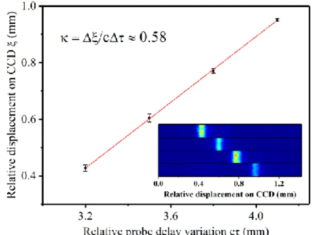
Figure 2: Temporal mapping relationship measurement. Insets are the single-shot EO signals with four different probe delay settings.
Error bars denote the deviations of 20 consecutive shots.
Soon after observing the EO signals, we examined the temporal mapping relationship by checking the EO signals at four different probe settings with fixed plasma density. To our surprise, the fitted relationship was different from the widely used model, as illustrated in Fig. 2. The fitted slope was 0.58, which was much smaller than 1/ tan 𝜃
𝑝≈1.03. This inconsistency suggested that the relative angle between the Coulomb field front and the electron propagation direction was larger than 𝜃
𝑝. The assumed model in which the Coulomb field is compressed orthogonally to the electron propagation direction is not applicable in our case.
In the case of LWFA, the electrons are emitted from plasma,
where electromagnetic components with frequencies smaller than
the plasma eigenfrequency are shielded. When we set the EO crystal very close to the plasma source, the free space condition would not be valid anymore. An analysis on the Liénard–
Wiechert potential shows that because the electromagnetic field propagates with the speed of 𝑐, the wavefront of the Coulomb field of the electron is spherical, as shown Fig. 3(a). Because the electron propagates with a speed smaller than c, when the electron is very close to the source position, the front of the field is attached to the electron. However, when the electron propagates for a long distance, the “free-space” condition becomes valid and the Coulomb field becomes perpendicular to the electron propagation direction, as shown in Fig. 3(c).
Figure 3: Static electric field analysis. The ln |𝐸
𝑦| distribution of a 30-MeV electron at propagation time of 3.3 ps (a), 3.3 ns (b), and 33 ns (c). X is the electron propagation direction and Y is the transverse direction.
Figure 4: Geometry for the calculation of a new temporal mapping relationship. The red straight lines and brown curved lines denote the wavefront of the probe laser and the THz signal field, respectively. The THz field incident angle on the EO crystal surface at transverse position 𝑦 and longitudinal distance of 𝐿 from the source position is 𝜃
𝑠0= arctan(𝑦/𝐿) . The probe incident angle is 𝜃
𝑝.
With the knowledge of the Coulomb field structure, we deduced a new temporal mapping relationship for the application of this method in LWFA. As illustrated in Fig. 4, the probe laser encounters a first line in the THz field at position 𝐴 and time 𝑡
𝐴and a second line in the THz field at position B and time 𝑡
𝐵. The two lines in the signal have a timing difference of Δ𝜏 and the recorded displacement on the CCD is Δ𝜉 = 𝜉
𝐵− 𝜉
𝐴. For a signal with a spherical wavefront, a new temporal mapping relationship is expressed in a nonlinear form as [7]:
𝑐Δ𝜏 = ∆𝜉 tan 𝜃
𝑝+
𝐿cos 𝜃𝑠0
−
𝐿
cos 𝜃𝑠0
√1 −
2 sin 𝜃cos 𝜃𝑠0cos 𝜃𝑠0𝑝
∆𝜉
𝐿
+
coscos22𝜃𝜃𝑠0𝑝
∆𝜉2 𝐿2
(1) Because the problem we investigate has a very small time scale, that is, Δ𝜉 ≪ 𝐿 , Eq (1) can be simplified as 𝑐Δ𝜏 = (1 +
sin 𝜃𝑐𝑜𝑠𝜃𝑠0𝑝
) tan 𝜃
𝑝∆𝜉 −
coscos 𝜃2𝜃𝑠0𝑝
∆𝜉2
2𝐿
. Ignoring the higher-order component, we have:
𝑐Δ𝜏 = (1 +
sin 𝜃sin 𝜃𝑠0𝑝
) tan 𝜃
𝑝∆𝜉 (2) Eq (2) describes the case in which the THz signal is a plane
wave and obliquely incident on the crystal at an angle of 𝜃
𝑠0. We note that when setting 𝜃
𝑠0= 0, Eq (2) returns to the widely used model: 𝑐Δ𝜏 = Δ𝜉 tan 𝜃
𝑝. In the experimental setup, the EO detection point corresponds to an angle of 𝜃
𝑠0= 34.3°. Using the fitted slope value in Fig. 2 and Eq (2), the average signal incident angle is calculated to be 𝜃
𝑠= 33.1°. This coincidence demonstrates that the Coulomb fields of the electron bunches near the source point have spherical wavefronts and Eq (2) is applicable for this method in LWFA.
In summary, we introduced, for the first time, the EO spatial decoding technique into LWFA. The temporal signals of the electron bunches have been nondestructively detected in single- shot mode. By setting the EO crystal very close to the plasma exit, we discovered that the Coulomb fields of the electron bunches have spherical wavefronts. A new temporal mapping relationship has been deduced to determine the real timing difference during the decoding process. We believe this study is of significance for the application of EO spatial decoding as a real-time electron bunch timing monitor in LWFA.
Acknowledgments
We acknowledge Prof. A. Zigler, Prof. P. Bolton, and Dr. A.
Pirozhkov for fruitful discussions, and Prof. Hosokai and Dr.
Sano for their encouragement. We thank H. Kotaki, M. Mori, Y.
Hayashi, and N. Nakanii for help with the experiment. We are grateful for the theoretical support from T. Esirkepov, J. K. Koga, and S. V. Bulanov. This work was funded by the ImPACT Program of the Council for Science, Technology and Innovation (Cabinet Office, Government of Japan).
References
1. T. Tajima and J. M. Dawson, Phys. Rev. Lett. 43, 267 (1979).
2. D. Strickland and G. Mourou. Opt. Commun. 55, 447 (1985).
3. M. Fuchs et al., Nat. Phys. 5, 826 (2009).
4. A. Rousse et al., Phys. Rev. Lett. 93, 135003 (2004).
5. J. van Tilborg et al., Phys. Rev. Lett. 96, 014801 (2006); O.
Lundh et al., Nat. Phys. 7, 219 (2011); A. D. Debus et al., Phys.
Rev. Lett. 104, 084802 (2010).
6. B. Stefen. No. DESY-THESIS-2007-020. DESY, (2007).
7. K. Huang et al., Sci. Rep. 8, 2938 (2018).
UV harmonics and proton generation from a thin-foil target with the J-KAREN laser
Akito Sagisaka, Alexander S. Pirozhkov, and Hiromitsu Kiriyama
Advanced Laser Group, Department of Advanced Photon Research
High-intensity laser and plasma interactions produce particle beams and electromagnetic waves such as high-energy electrons, high-energy ions, and high-order harmonics [1–5].
High-order harmonics have been observed in the relativistic regime with gas [6–8] and solid targets [9–12]. In a gas target, burst intensification by singularity emitting radiation (BISER) is observed [6–8]. In the case of a solid density target, the models of harmonic generation in the relativistic regime include the relativistic oscillating mirror model [3,13,14] and the sliding mirror model [15,16]. In these models, the laser pulse reflected from an oscillating or sliding overdense layer of plasma electrons is modulated and its spectrum contains high-order harmonics. High-energy protons have been observed at the rear side of the thin-foil target [4,5]. In this experiment, UV harmonics in the relativistic regime with protons using an aluminum (Al) foil target irradiated with the J-KAREN laser are observed.
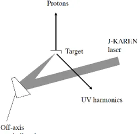
The J-KAREN laser system [17,18] is used as a high-intensity laser. The pulse duration of the laser in this experiment is ~35 fs (FWHM). A schematic of the experimental setup is shown in Figure 1. A p-polarized laser pulse is focused with an off-axis parabolic mirror onto a target at an angle of incidence of 45˚. The estimated peak intensity is up to
~10
21W/cm
2with the effective pulse duration and effective spot size [19]. The protons are measured with a stack of RCF and CR-39 detectors [20–22]. The reflected UV harmonics are measured with a fiber spectrometer [22,23]. The harmonic radiation is scattered from a PTFE sheet [24,25] and passes through a fiber. A UV harmonic spectrum obtained with a 2-µm-thick Al target is shown in Figure 2 [22]. The sharp peaks
are from hard X-rays generated by the laser–plasma interaction.
The third- and fourth-order harmonic peaks are broadened and shifted on some shots. The red shift and broadening of the harmonic spectrum can be caused by the Doppler shift at the critical density [26–29] and the relativistic self-phase modulation of the laser as it passes through the preformed plasma [30,31]. The preformed plasma generation at the target front side is considered from the spectral shift and broadening.
The observation of UV harmonics in the relativistic regime is useful for the diagnostics of the laser and thin-foil interaction.
High-energy protons are observed with a thinner target.
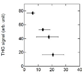
The maximum proton energy is ~39 MeV for a 0.8-µm-thick Al target. The third- and fourth-order harmonics are measured for this shot. The integrated third-order harmonic signal as a function of the deflection angle of the proton beam with energies of from around 34 MeV to around 36 MeV obtained from separate laser shots with various fluctuations is shown in Figure 3 [22]. Vertical bars are error bars. Horizontal bars are widths of the proton beam pattern. The deflection angle is taken to be the angle between the proton beam toward the laser beam direction and the target normal direction. The third-order harmonic signal decreases with the deflection angle of the proton beam rather than the proton energy, suggesting that the target rear side deformation from the laser prepulse is likely the relevant reason. This assumes that the UV harmonic intensity decreases as the target front side preformed plasma and target rear side deformation increase, considering that the change in the preformed plasma is related to the fluctuation of the prepulse condition.
Simultaneous generation of UV harmonics and high-energy protons from a thin-foil target are observed in the relativistic regime with the J-KAREN laser.
Fig. 2 UV harmonic spectrum with an Al foil target.
Reprinted with permission from [22].
Fig. 1 Schematic view of the experimental setup.
Acknowledgments
We thank K. Ogura, M. Nishiuchi, H. Sakaki, T. Zh Esirkepov, M.
Kando, A. Ya. Faenov, T. A. Pikuz, S. V. Bulanov, and K. Kondo for their contributions.
References
1. G. A. Mourou et al., Rev. Mod. Phys. 78, 309 (2006).
2. U. Teubner and P. Gibbon, Rev. Mod. Phys. 81, 445 (2009).
3. S. V. Bulanov et al., Phys. Usp. 56, 429(2013).
4. H. Daido et al., Rep. Prog. Phys. 75, 056401 (2012).
5. A. Macchi et al., Rev. Mod. Phys. 85, 751 (2013).
6. A. S. Pirozhkov et al., Phys. Rev. Lett. 108, 135004 (2012).
7. A. S. Pirozhkov et al., New J. Phys. 16, 093003 (2014).
8. A. S. Pirozhkov et al., Scientific Reports 7, 17968 (2017).
9. B. Dromey et al., Nature Phys. 2, 456 (2006).
10. B. Dromey et al., Phys. Rev. Lett. 99, 085001 (2007).
11. C. Thaury et al., Nature Phys. 3, 424 (2007).
12. A. Tarasevitch et al., Phys. Rev. Lett. 98, 103902 (2007).
13. S. V. Bulanov et al., Phys. Plasmas: 1, 745 (1994).
14. R. Lichters et al., Phys. Plasmas 3, 3425 (1996).
15. A. S. Pirozhkov et al., Phys. Plasmas 13, 013107 (2006).
16. A. S. Pirozhkov et al., Phys. Lett. A 349, 256 (2006).
17. H. Kiriyama et al., Opt. Lett. 35, 1497 (2010).
18. H. Kiriyama et al., IEEE Sel. Topics J. Quantum Electron, 21, 1601118 (2015).
19. A. S. Pirozhkov et al., Opt. Express 25, 20486 (2017).
20. K. Ogura et al., Opt. Lett. 37, 2868 (2012).
21. M. Nishiuchi et al., Phys. Plasmas 22, 033107 (2015).
22. A. Sagisaka et al., The Review of Laser Engineering, 46, 148 (2018).
23. I. W. Choi et al., Appl. Phys. Lett. 99, 181501 (2011).
24. A. S. Pirozhkov et al., Appl. Phys. Lett. 94, 241102 (2009).
25. A. S. Pirozhkov et al., in 2nd Int. Symp. Laser-Driven Relativistic
Plasmas Applied to Science, Industry and Medicine, AIP Conf. Proc.1153, 7 (2009).
26. M. Zepf et al., Phys. Plasmas 3, 3242 (1996).
27. M. P. Kalashnikov et al., Phys. Rev. Lett. 73, 260 (1994).
28. S. C. Wilks et al., Phys. Rev. Lett. 69, 1383 (1992).
29. W. L. Kruer et al., Phys. Rev, Lett. 35, 1076 (1975).
30. C. A. Coverdale et al., Fiz. Plazmy,
22, 685 (1996) [Plasma Phys.Rep. 22, 617 (1996)].
31. I. Watts et al., Phys. Rev. E 66, 036409 (2002).
Fig. 3 Integrated third-order harmonic signal as a function
of the deflection angle of the proton beam. THG stands
for third-order harmonic generation. Reprinted with
permission from [22].
High-repetition, multi-MeV, pure proton source via Coulomb explosion of micron-scale hydrogen cluster targets
Yuji Fukuda, Ryutaro Matsui and Hiromitsu Kiriyama
Advanced Laser Group, Department of Advanced Photon Research
Laser-driven ion acceleration has been one of the most active areas of research over approximately the past decade, because accelerated multi-MeV ion beams have unique properties that can be employed in a broad range of applications, including nuclear science, hadron cancer therapy, and fast ignition for inertial confinement fusion. Recent advancements in laser-driven ion acceleration techniques using thin-foil targets allow maximum proton energies close to 100 MeV. From the perspective of practical applications, high-purity proton beams with high reproducibility are quite advantageous. In experiments using thin-foil targets, however, protons from surface contaminants along with high-z component materials are accelerated together, making the production of impurity-free proton beams unrealistic.
Here, we introduce a micron-scale hydrogen cluster, composed of 10
8–10hydrogen molecules, as a target to generate impurity-free, highly reproducible, and robust multi-MeV proton beams [1,2]. Because of the recent progress in intense laser technology, advanced PW-class lasers can now achieve intense laser fields of approximately 10
22W/cm
2. With such fields, all the electrons inside a micron-scale hydrogen cluster up to 3.0 μm in diameter can be fully stripped off, resulting in a pure Coulomb explosion with a pronounced increase in the maximum accelerated proton energies, scaled as E
max= 276( d/2)
2MeV, where d is the cluster diameter. For example, 100-MeV protons
could be produced via the Coulomb explosion of a 1.2-μm- diameter hydrogen cluster under irradiation by a laser pulse with a peak intensity of 1.6 × 10
21W/cm
2[2]. The robust nature of the Coulomb explosion mechanism offers an additional advantage for practical applications.
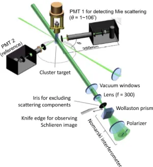
Hydrogen clusters with diameters in the few-micrometer range have been produced for the first time in an expansion of supercooled, high-pressure hydrogen gas into a vacuum through a conical nozzle connected to a cryogenic pulsed solenoid valve [1,2]. The size distribution of the clusters has been evaluated by measuring the angular distribution of laser light scattered from them (see Fig. 1). The data were analyzed based on the Mie scattering theory combined with the Tikhonov regularization method, including instrumental functions, the validity of which was assessed by performing a calibration study using a reference target consisting of standard microparticles with two different sizes. The size distribution of the clusters was found to show discrete peaks at 0.33 ± 0.03, 0.65 ± 0.05, 0.81 ± 0.06, 1.40 ± 0.06, and 2.00 ± 0.13 μm in diameter, as shown in Fig. 2.
Fig. 1 Schematic of experimental setup for the cluster size measurement using Mie scattering and for the gas phase density measurement using a Nomarski interferometer.
Fig. 2 Size distributions of hydrogen clusters measured using the Mie scattering method at the pulsed valve temperature of 25 K and the hydrogen gas pressure of 6 MPa.
Fig. 3 Schematic of experimental setup for laser-driven proton acceleration using the micron-scale hydrogen clusters.
57.4
MCP with p-plate CCD
Thomson parabola Cooled pulsed valve
Laser 1 1020W/cm2
~10 J, 40 fs, 0.1 Hz
RCF/CR-39 Nuclearemulsion
Fluorescent nuclear track detector Hydrogen clusters
0.3-2.0 um in dia. (25 K)
Experimental setup: Multi-MeV Pure Proton Beam
5