CATALOG
No.17
本社・工場 Head office/Factory/
〒947-0042 新潟県小千谷市平沢2丁目11番19号 2-11-19 HIRASAWA OJIYA-CITY, NIIGATA-PREF., 947-0042 JAPAN TEL.0258-82-3331 FAX.0258-81-1288 営業部 Sales division/
TEL.0258-81-1277 FAX.0258-83-4002 E-mail: [email protected]
東京営業所 Tokyo office/
〒101-0034 東京都千代田区神田東紺屋町28番地 那智ビル7F 28 KANDA HIGASHI KONYA-CHO, CHIYODA-KU, TOKYO, 101-0034 JAPAN TEL.03-5207-7211 FAX.03-3252-1160
E-mail: [email protected]
本カタログに掲載された製品は、改良のため予告なく仕様変更を行うことがあります。
The products and specifications on this catalogue are subject to change without prior notice for improvement.
http://www.ojiyas.co.jp
CATALOG No.17 OJIYASEIKI CO.,LTD.
OJIYA SEIKI CO., LTD.
OJIYA
(小千谷)
TOKYO新潟県の鑑賞魚「 錦鯉 」。一般的には
「観賞魚」と表記しますが錦鯉は美術的な 価値があるという意味を含めて「鑑賞」
の文字を使用しています。
Nishikigoi(Colored carp) is a specified fish in Niigata prefecture.
空気マイクロメータ用測定子 ――――――――――― 11
Air Jet Gauge for Air Micrometer
▶
IA型内径測定子 ――――――――――――――― 11
Air Jet IA Type for Inside Diameter
▶
IB型内径測定子 ――――――――――――――― 12
Air Jet IB Type for Inside Diameter
▶
IC型内径測定子 ――――――――――――――― 13
Air Jet IC Type for Inside Diameter
▶
LA型・LB型内径測定子 ―――――――――――― 14
Air Jet LA and LB Types for Inside Diameter
▶
VC型・LV型外径測定子 ―――――――――――― 15
Air Jet VC・LV Type for Outside Diameter
▶
OR型・LR型外径測定子 ―――――――――――― 15
Air Jet OR・LR Type for Outside Diameter
測定例 ―――――――――――――――――――― 10
Measurement applications
空気マイクロメータ用多連式測定台――――――――― 10
Various fi xture gauges for air micrometer measurement
空気マイクロメータ用マスタゲージ ――――――――― 16
Master Gauges for Air Micrometer
▶
LF-CS ad-LF専用通信ソフト ――――――― 5
Software for data communication for ad-LF
▶
ad-L8 デジタル式空気マイクロメータ ――― 7
Digital Type Air Micrometer
▶
AIR GIRLⅡ 流量式空気マイクロメータ ――――― 9
Flow Type Air Micrometer
JIS 認証 JQ 0308165
認証区分 Certifi cate Classifi cation JIS B 0251 メートルねじ用限界ゲージ JIS B 0253 管用テーパねじゲージ JIS B 0254 管用平行ねじゲージ JIS B 0255 ユニファイねじ用限界ゲージ
ISO 14001 認証 JQA-EM 3887
登録活動範囲 Scope of Registration 各種ゲージ、空気マイクロメータの 設計・開発・製造および校正
Design/Development/Production and Calibration of Precision Gauges, Air Gauges.
本社・東京営業所 Head offi ce/Tokyo offi ce ISO 9001 認証
JQA-QM 3908
登録活動範囲 Scope of Registration 各種ゲージ、空気マイクロメータの 設計・開発・製造および校正
Design/Development/Production and Calibration of Precision Gauges, Air Gauges.
本社・東京営業所 Head offi ce/Tokyo offi ce
平行ねじ用限界ゲージ― ―――――― 19
Limit―Gauges―for―Parallel―Screw―Threads
ねじ用限界ゲージの種類と関係図― ― 43
Chart―of―Mutual―Relationships―of―Limit―
Gauges―for―Screw―Threads
標準ねじゲージ― ――――――――― 19
Standard―Thread―Gauges
新JIS(ISO)におけるゲージシステム―― 45
Gauging―System―in―new―JIS―(ISO)
管用平行限界ねじゲージ― ――――― 20
Limit―Gauges―for―Parallel―Pipe―Threads
技術資料 ――――――――――― 46
Technical―Information
管用テーパねじゲージ― ―――――― 21
Gauges―for―Taper―Pipe―Threads
会社概要 ――――――――――― 51
Introduction―to―OJIYA―SEIKI
限界プラグゲージ― ―――――――― 25
Limit―Plug―Gauges
限界リングゲージ― ―――――――― 26
Limit―Ring―Gauges
超硬ゲージ―――――――――――― 26
Carbide―Gauges
限界ハサミゲージ― ―――――――― 27
Limit―Snap―Gauges
マスタゲージ・スプラインゲージ・テーパゲージ ――――――28
Master―Gauges・Spline―Gauges・Taper―Gauges
特殊ゲージ ――――――――――――――――――――29
Special―Gauges
ビット付ねじプラグゲージ Bit-Plus― ―――――――――30
Thread―Plug―Gauge―with―Hex―Drill―Bit―Shank
三次元マスタゲージ CPG ―――――――――――――31
Thread―Hole―Location―Gauges
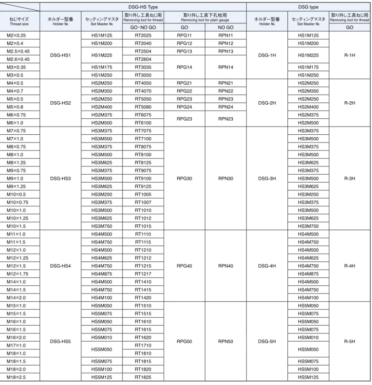
目盛付ねじ深さゲージ DSG・DSG-HS― ―――――――33
Thread―Depth―Gauges―with―Graduation―Scale
在庫表 ―――――――――――――――――――――36
Stock―List
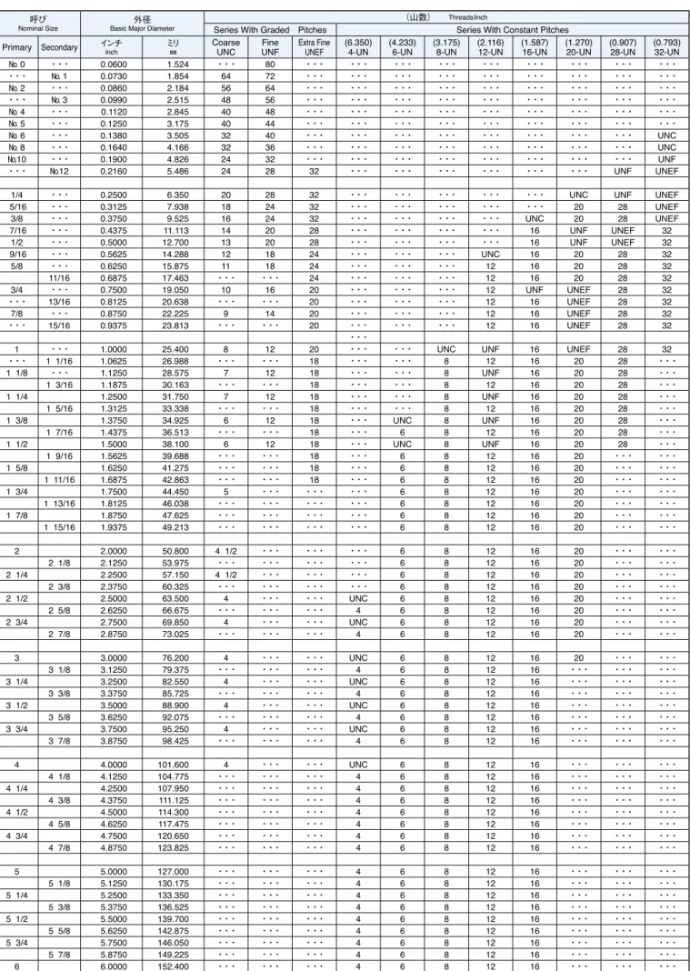
主なねじ規格一覧表 ――――――――――――――――41
List―of―Major―Thread―Specifications
空気マイクロメータは微小な寸法変位量を高圧の空気の量や 背圧(差圧)を利用し流体力学の原理を応用した精密比較測 定器です。無接触で迅速に測定ができ、さらに被測定物の実測 寸法を読み取ることができます。測定点数に応じ容易に多連式 に積み上げることができることも大きな特長です。品質管理、測 定能率の向上に最適な測定器です。
Air micrometer is a precision comparator type measuring instrument that employs air flow volumes and air pressure to determine the size of measured part dimensions. Operation is noncontact and is as simple as presenting a tool to a workpiece and observing a reading. A row of multiple column can be used for measuring several measuring points in one glance that can reduce measurement times.
The benefit of air gauging is its ease of use, which produces accurate results even when used by unskilled operators. Therefore, air micrometer is an effective and efficient shopfloor measuring tool used in quality control.
AIR MICROMETER
空気マイクロメータ
AIR GIRL Ⅱ
特長
Featuresオプション
Option新機能
New functionsDigital Type Air Micrometer
A fix magnification type with weight reduced compact body
デジタル式空気マイクロメータ
●従来の機能を引き継ぎ、さらに使い易いキー入力
●マスタ合わせ画面へのダイレクト遷移機能
●最大値、最小値および数値の差を表示
●パスワードによる書き換え防止機能
● Easier key input on the current functions
● Direct jump to mastering display via I/O device
● Displays Max and Min values and its subtraction
● Password for rewriting program protection
1 差圧センサー採用による安定した測定値 2 2.4 インチ液晶表示による容易なセッティング 3 41 ドット3色 LED バーグラフ表示(緑、赤、橙)
4 接続台数は最大8台まで可能
5 測定レンジ 0.010mm 〜 0.200mm の5タイプ 6 表示分解能 0.0001mm 〜 0.0020mm
7 RS485 出力ポート装備
1 Differential pressure sensor provides excellent stability reading 2 2.4 inch TFT LCD screen for easy programming
3 41 dots 3 colors LED bar (green, red and orange)
4 Maximum 8 columns connections
5 5 measurement ranges of 0.010mm 〜 0.200mm 6 Display resolution of 0.0001mm 〜 0.0020mm 7 RS485 port for serial interface connection
より軽量、コンパクトボディ、固定倍率仕様
Data communication software for use with ad-LF
ad-LF 専用通信ソフト LF-CS
パソコンへのデータ送信が可能です
Excel 上で測定データの集計と統計処理が簡単に行えます
By using this software, the measured data can be transferred to Excel sheet on the PC for further
statistical processing, such as process capability analysis
仕様
Specifications性能
Performances商品コード
Code No. 型式
Model 測定レンジ
Measurement Range 表示分解能
Display Resolution
92001001 ad-LF10 0.010mm 0.0001mm
92002001 ad-LF20 0.020mm 0.0002mm
92005001 ad-LF50 0.050mm 0.0005mm
92010001 ad-LF100 0.100mm 0.0010mm 92020001 ad-LF200 0.200mm 0.0020mm
LEDバー表示
LED Bar Graph
41ドット
41dotデジタル表示
Digital Display
2.4インチカラー液晶
2.4 inch
TFT Color LCD 自動マスタ補正範囲Auto Mastering Range 大範・小範合せ値 ±50%
Master Max・Master Min シリアル出力
Output Interface
RS485
ランク選別機能
Rank Function 最大100ランク(OK領域) Max 100 rank 本体寸法Dimension
Width幅 奥行
Depth 高さ
Height 質量
Weight
55mm 130mm 400mm 2.4kg
電源供給電圧Power Supply
DC9V(ACアダプタ100V~240V付属)
DC9V(With AC adapter for 100V~240V)
電圧変動率
Voltage variation rate ±10%以内 within ±10%
Frequency周波数
50Hz/60Hz
Current consumption消費電流
0.18A(MAX)
供給空気圧
Air Presure
350~700kPa
Operating Temperature動作温度
0~40℃
測定レンジ Range 項目 Items
判定基準(許容値)
Standard Performances
10μm 20μm 50μm 100μm 200μm
基準内器差
Instrumental error
0.2μm 0.4μm 1.0μm 2.0μm 4.0μm
繰返し精度
Repeatability
0.2μm 0.2μm 0.5μm 1.0μm 2.0μm
指示の安定性
Stability of indication
0.2μm 0.2μm 0.5μm 1.0μm 2.0μm
Response Time応答時間
1.5秒以内
Max 1.5 sec
1.2秒以内
Max 1.2 sec 有効指示範囲
Effective indication Range
10μm 20μm 50μm 100μm 200μm
LF-CS
特長
Features動作環境
System requirementsSoftware for data communication for ad-LF
ad-LF 専用通信ソフト
デジタル式空気マイクロメータ ad-LF からの測定データを収集する Excel の専用ソフトウェアです。
低コストで導入でき、簡単に操作できますのでデータ管理および統計処理が容易に行えます。
An Excel software dedicated for collecting measured data from digital type air micrometer ad-LF.
The software helps you monitoring and measuring the characteristic of the products using process capability analysis tool, with an easy operation at a low cost.
1 ad-LF とパソコンを接続することによりエクセルシートに測定データを出力します 2 本ソフトウェアは機能の異なる5つのシートから構成されています
3 測定データを演算することにより工程能力解析を行いグラフ化ができます 4 最大8台の ad-LF から測定データを収集および管理することができます
1 Measured data from ad-LF are transferred into the Excel sheets on the connected PC
2 The software consists of 5 different function sheets of setting, data collecting and analyzing sheets 3 A control chart and capability analysis indices are calculated from the measured data
4 The measured data from maximum 8 columns of ad-LF can be collected into one sheet
ハードウェア Hardware 構成条件 Specification プロセッサ CPU
Intel Core i5 相当以上
or higherメモリ Memory
2GB 以上
or moreハードディスク Hard disk 空き容量 16GB 以上 or more available space 通信ポート Communication port
USB port
入力装置 Input device マウスおよびキーボード Mouse and keyboard ソフトウェア Software 構成条件 Specification
OS
OSMicrosoft windows 7(32bit, 64bit)以降
or laterMicrosoft Excel
Microsoft ExcelMicrosoft Excel 2007
(32bitのみ)以降
32 bit only or later注意事項
Informations▶基本測定シート
Simple Measure sheet
▶演算シート
Calculation sheet
▶拡張測定シート
Extended Measure sheet
▶工程能力解析シート
Process Capability sheet
本ソフトウェアを使用するには ad-LF 本体、RS232 オス・メスストレートケーブル、RS485 通信を USB 通信に変換す る USB-RS485 の変換アダプタおよび USB ポートのあるパソコンが別途必要です。なお、仕様の詳細は弊社営業部にお 問合せください。
To connect ad-LF into a PC, a USB-RS485 adapter and RS232 male-female cables are required. Please contact our sales division for further information.
●製品の仕様、外観は改良のため予告なく変更する場合があります
● Excel は米国 Microsoft 社の登録商標または商標です
● The specifications and appearances of this software are subject to change without prior notice for further improvement
● Excel is a registered trademark or a trademark of American Microsoft corporation
Some of software contents
通信ソフト画面例
メニュー概要
Menu Configurationメインメニュー Main Menu
測定モード Measuring Mode
プログラム読込確認
Loadプログラム編集確認
Editプログラム削除確認
Deleteランク分別方法選択
Rank MethodブザーON/OFF 選択 Buzzer ON/OFF 保存スロット選択
Save Area Select自動マスタ補正
Auto Mastering日本語/英語
Japanese/Englishプログラム選択
Program Select測定選択
Measuring Object測定範囲選択
Range Select寸法表示選択
Unit Select判定基準値設定
Limit Entry初期化確認
Initializationプログラム名入力
File Nameマスタ調整
Master Adjustマスタ値確認
Master Confirmationブザー選択
Buzzer Selectランク使用選択
Rank Select上限下限値入力
Master Entry Language Select言語選択
プログラムメニュー
Program Menu設定メニュー
Setting Menuマスタ調整
Mastering Methodリセット確認
Reset All DataDigital Type Air Micrometer
デジタル式空気マイクロメータ
使いやすさと見やすさを追求したコラム型デジタル式空気マイクロメータです。
アナログ3色カラーバー(緑色、赤色、橙色)表示と TFT カラー液晶ディスプレイの 採用でセッティング、マスタリング時の操作入力はもちろん測定寸法の把握も素早く対 応できます。
空気回路は差圧センサーを採用したことにより元圧側の圧力変動に測定値が影響されな い仕様となっています。
A column model air micrometer with a great emphasis upon ease of use and viewing.
By using 3 colors (red, green and orange) LED bar and TFT LCD screen, operation for paramater setting and identification of measured results can be easily and quickly accomplished.
Differential pressure type circuit is adopted to compensate the variations in the pressure of the air source that could spoil the measurement.
測定システムはエアマイクロメータ本体(フィルタユニット、接 続用ウレタンホース:標準付属品)と測定ジェットおよびマスタ ゲージで構成されています。
なお測定ジェットには接続用ビニールホースが附属されています。
The AIR MICROMETER measurement unit consists of the main body of AIR MICROMETER (including the filter unit, hose for connection as standard accesories), air jet and master guages. Vinylhose is attached in the air jet for connection.
操作は液晶画面に表示される メニューから選択と入力 !!
The operations are performed from the visible menu displayed on
the LCD screen.
特長
Features仕様
Specifications性能
Performances1 日本語、英語表示切換え機能搭載 2 操作性抜群のパネルスイッチ
17 の独立キースイッチでスピーディーな入力が可能 3 自動マスタ補正機能
大範、小範を使用して自動でセッティングします 4 ワーク寸法ランク選別機能
OK 領域で任意設定、最大 100 ランク 5 最大、最小測定寸法を表示
最大、最小の差で真円度、テーパ度の測定ができます 6 測定、判定結果を数値と音でお知らせ
データ表示の他ブザー音を任意で設定できます 7 シリアル出力に USB ポート、RS485 装備
パソコン、RS485 対応インタフェースへのデータ出力を行います 1 Japanese/English language selection function
2 Excellent operability provided by panel switch having 17 button keys 3 Auto master compensation function
Auto mastering using maximum and minimum masters
4 Rank function for sorting the measured values into a group of values Rank is available up to 100 ranks within the OK zone
5 The maximum and minimum peak detection is available
The peak detection can be used to measure the roundness, taper degree
6 Buzzer and digital display are used for exhibiting the measured results and their OK/NG status
Buzzer can be set optionally from extended menu 7 USB connector, RS485 for serial interface
To send the measured results to the computer and RS485 compatible interface
本体寸法Dimension 巾 Width
50mm
奥行 Depth197mm
高さ Height527mm
質量 Weight4kg
Power Supply電源供給
AC100V~AC240V
Power Capacity電源容量
30VA
電圧変動率
Voltage Regulation
20%以下 within 20%
Frequency周波数
50Hz/60Hz
供給空気圧
Air Pressure
350~700kPa
Operating Temperature使用温度
0~40℃
測定レンジ
Measurement Range
20μm 50μm 100μm 200μm
表示分解能
Display Resolution
0.2μm 0.5μm 1μm 2μm
LED Bar Graphバー表示
101ドット
101dotデジタル表示
Digital Display カラー液晶(LCD)表示 TFT Color LCD 自動マスタ補正範囲
Auto Mastering Range
大範合せ値 小範合せ値
Master Max -
20
% Master Min +20%
シリアル出力
Serial Output
USBポート
USB port, RS485 ランク機能Rank Function 最大100ランク(OK領域)Max 100 rank
測定レンジ Range 項目 Items
判定基準(許容値)
Standard Performances
20μm 50μm 100μm 200μm
基準内器差
Instrumental error
0.4μm 1μm 2μm 4μm
*繰返し精度
Repeatability
0.2μm 0.5μm 1μm 2μm
指示の安定性
Stability Indication
0.2μm 0.5μm 1μm 2μm
Response Time応答時間
1.2秒以内
Max 1.2 Sec 有効指示範囲
Effective Indication Range
20μm 50μm 100μm 160μm
*測定範囲が200μmの場合、有効指示範囲の160μmにおいて判定基準値が4μmですが、フルレンジにおいては6μmです
* For measurement range of 200μm, the instrumental error of 4μm is for effective indication range of 160μm. For full range of 200μm, the standard of instrumental error is 6μm
特長
Features仕様
Specifications性能
PerformancesFull model change into a compact body type with about 50% weight reduction of the old model.
フルモデルチェンジにより 50%の軽量化が図られ、
コンパクトボディへと生まれ変わりました。
1 大胆なS字フォルムのデザイン
2 テーパガラス管のメンテナンスが容易にできます 3 フロートの応答速度が速く安定性に優れています 4 性能は JIS B 7535 の基準を満たしています 5 容易に多連式に構成できます
1 Daring S-shaped design
2 Taper glass pipe can be maintained easily 3 Quick float speed with superior stability
4 Performances satisfiy the standard of JIS B 7535 5 Easy to change to multiple columns
型式は基準倍率
1000 倍、2000 倍、5000 倍、10000 倍の4機種となります
4 type magnification ranges of × 1000、× 2000、× 5000、× 10000
標準付属品:
フィルタユニット
(
フィルタユニット1台で本体3連まで接続できます)
接続用ウレタンホース Standard attachment:
The filter unit
(
1 filter unit for 3 columnsconnection)
Urethane hose for connections
Columns No.連数 本体幅
Width
mm
幅(脚含む)Total width mm 奥行
Depth mm 高さ
Height mm 質量
Weight kg
単式 Single
50 100 163 505 2.1
2連式 Double
100 140 163 505 4.0
3連式 Three
150 190 163 505 5.9
4連式 Four
200 240 163 505 7.8
5連式 Five
250 290 163 505 9.7
6連式 Six
300 340 163 505 11.6
項目 Items
型式 Model AIR GIRL Ⅱ 商品コード Code No.
AIR GIRL Ⅱ 1000
93001001 AIR GIRL Ⅱ 2000
93002001 AIR GIRL Ⅱ 5000
93005001 AIR GIRL Ⅱ 10000 93010001
基準倍率(倍)Standard magnification(times)
1,000 2,000 5,000 10,000
指示範囲(μm)
Indication range
200 100 40 20
有効指示範囲(μm)
Effective indication range
150 70 30 15
目量(μm)
Graduation
5 2 1 0.5
指示誤差(μm)
Indication error
3.0以下(Max) 1.5以下(Max) 1.0以下(Max) 0.5以下(Max)
指示の繰返し性(μm)
Indication variance
2.0以下(Max) 1.0以下(Max) 0.5以下(Max) 0.3以下(Max)
応答時間(秒)
Response time (sec)
1.5以下(Max) 1.5以下(Max) 1.8以下(Max) 2.0以下(Max)
供給空気圧(kPa)
Air pressure supplied
300~700
Flow Type Air Micrometer
流量式空気マイクロメータ
内径・真円度の測定
Inside diameter, Circularity toleranceMultiple measurement
多連測定
3連式外径測定台
For measuring outsidediameter (3 columns)
3連式内・外径測定台
For measuring inside and outside diameter (3 columns)5連式内・外径・直角度測定台
For measuring inside, outside diameterand perpendicularity (5 columns)
テーパ外径測定台
For measuring outsidediameter of taper
ピッチ測定台
For measuring pitch
3連式高さ測定台
For measuring height(3 columns)
4連式厚み測定台
For measuring thinckness(4 columns)
2連式内・外径測定台
For measuring inside and outside diameter (2 columns)内径と端面の直角度測定
Perpendicularity between inside diameter and edge part
外径と端面の直角度測定
Perpendicularity between outside diameter and edge part内径・円筒度の測定
Inside diameter, Cilindricity tolerance
外径・真円度の測定
Outside diameter, Circularity tolerance外径・円筒度の測定
Outside diameter, Cilindricity tolerance高さ・厚み測定
Height, Thickness▶ 測定例 Measurement applications
▶ 空気マイクロメータ用多連式測定台 Various fixture gauges for air micrometer measurement
ノズル位置がジェット先端より8〜20mmにあり、主に通り穴の 測定に用いられます。
The nozzle position is 8-20mm from the top point.
It is used to measure the through hole.
呼び寸法 φd 超え ~ 以下
Nominal Size φd exceeded ~ less
L1 L2 L3 L4
4を超え 8以下 4 exceeded 8 or less
33 L4 10
L3 L2
φd L1
8 20 30 90
8を超え 11.5以下 8 exceeded 11.5 or less
L3 L2L1
35 L4 10
φd
8 20 30 90
11.5を超え 14以下 11.5 exceeded 14 or less
L4 L2
L3 10
L1
φd
15 45 5 85
14を超え 24以下 14 exceeded 24 or less
L2 L3 L4
L1
φd
20 45 5 85
24を超え 40以下 24 exceeded 40 or less
L3
L4 L2
L1
φd
20 45 5 85
40を超え 50以下 40 exceeded 50 or less
L2 L3 L4
L1
φd 20 50 10 100
50を超え 65以下 50 exceeded 65 or less
L2 L3 L4
4-軽減穴 4-HOLE L1
φd
20 50 10 100
65を超え 100以下
65 exceeded 100 or less 20 50 10 100
φ50を超えるサイズは軽減穴が付いた形状となります。
The size that exceeds φ50 is the shape with lightened hole.
IA型内径測定子(直吹タイプ)
Air Jet IA Type for Inside Diameter(Direct type)
ノズル位置がジェット先端より3〜4mmにあり、主に止り穴の 測定に用いられます。
The nozzle position is 3-4mm from the top point.
It is used to measure the blind hole.
呼び寸法 φd 超え ~ 以下
Nominal Size φd exceeded ~ less
L1 L2 L3 L4
4を超え 8以下 4 exceeded 8 or less
φd
33 L4 10
L3 L2
L1 3 20 30 90
8を超え 11.5以下 8 exceeded 11.5 or less
φd
L4 10
L3 L2L1
35
4 20 30 90
11.5を超え 14以下 11.5 exceeded 14 or less
φd
L4
L2 10
L1
L3
4 45 5 85
14を超え 24以下 14 exceeded 24 or less
L2 L3 L4
φd
L1 4 45 5 85
24を超え 40以下 24 exceeded 40 or less
L3
L4 L2
L1
φd
4 45 5 85
40を超え 50以下 40 exceeded 50 or less
φd
L2 L1
L4 L3
4 50 10 100
50を超え 65以下 50 exceeded 65 or less
φd
L2 L3 L4
4-HOLE
L1
4-軽減穴
4 50 10 100
65を超え 100以下
65 exceeded 100 or less 4 50 10 100
φ50を超えるサイズは軽減穴が付いた形状となります。
The size that exceeds φ50 is the shape with lightened hole.
IB型内径測定子(直吹タイプ)
Air Jet IB Type for Inside Diameter(Direct type)
ノズル位置がジェット先端より2mmにあり、主に止り穴の測定 に用いられます。
The nozzle position is 2mm from the top point.
It is used to measure hole at the deeper point.
呼び寸法 φd 超え ~ 以下
Nominal Size φd exceeded ~ less
L1 L2 L3 L4
4を超え 8以下 4 exceeded 8 or less
φd
33 L4 10
L3 L2 L1
2 20 30 90
8を超え 11.5以下 8 exceeded 11.5 or less
L4 10
35
φd
L3 L2
L1 2 20 30 90
11.5を超え 14以下 11.5 exceeded 14 or less
L4 10
L2 L3
φd
L1 2 25 5 85
14を超え 24以下 14 exceeded 24 or less
L3
L4
φd
L2
L1 2 25 5 85
24を超え 40以下 24 exceeded 40 or less
L3
L4
φd
L2
L1 2 25 5 85
40を超え 50以下 40 exceeded 50 or less
L2 L3 L4
L1
φd 2 25 10 100
50を超え 65以下 50 exceeded 65 or less
φd
L2 L4
L3 L1
4-HOLE4-軽減穴
2 25 10 100
65を超え 100以下
65 exceeded 100 or less 2 25 10 100
φ50を超えるサイズは軽減穴が付いた形状となります。
The size that exceeds φ50 is the shape with lightened hole.
IC型内径測定子(直吹タイプ)
Air Jet IC Type for Inside Diameter(Direct type)
コンタクトリーフ(板バネ)の測定ポイント部に超硬ボールを用い測定する接触式測定子です。
主に測定面の幅が4mm以下または、表面粗さが6.3μm Rzより粗い場合に用いられます。
超硬ポイントが測定ヘッドの中間よりにあるタイプがLA型 となります。
▶中間シャンク付内径測定子 Air jet for inside diameter with center shank
● ハンドルタイプのエアマイクロメータ用内径測定子で深穴等を測定したい時は、中間シャンクを接続することにより簡単に首下を長 くすることができますので、必要に応じお申し出下さい。
(中間シャンクで対応できる穴径はφ11を超えるサイズとなります)
●中間シャンク長さは50L、75L、100Lの組み合わせとなります。
超硬ポイントが測定ヘッドの先端にあるタイプがLB型とな ります。
It is a contact type air jet which uses carbide ball on the measurement point.
It is used to measure the workpieces having surface roughness more than 6.3μm Rz or width of the measured surface less than 4 mm.
LA type is the type with position of carbide ball in the middle of the jet.
● For measuring such deep holes using handle type air jet for air micrometer, the neck of air jet can be lengthened by connecting a center shank. Please notify us when you have request on this matter. (Note: The hole diameter that can be coped with by the center shank is beyond φ11 mm)
●50L,75L and 100L is available for a center shank.
LB type is the type with position of carbide ball in the top of the jet.
L2 5 L3
φd
L1
呼び寸法 φd 超え ~ 以下
Nominal Size φd exceeded ~ less
L1 L2 L3
10を超え 14以下10 exceeded 14 or less 7 45 95
14を超え 20以下
14 exceeded 20 or less 8 45 85
20を超え 24以下
20 exceeded 24 or less 10 45 85
24を超え 40以下
24 exceeded 40 or less 10 45 85
40を超え 50以下
40 exceeded 50 or less 15 50 100
50を超え 65以下
50 exceeded 65 or less 15 50 100
65を超え 100以下
65 exceeded 100 or less 15 50 100
L2 5 L3
φd
L1
呼び寸法 φd 超え ~ 以下
Nominal Size φd exceeded ~ less
L1 L2 L3
10を超え 14以下10 exceeded 14 or less 4 45 95
14を超え 20以下
14 exceeded 20 or less 4 45 85
20を超え 24以下
20 exceeded 24 or less 4 45 85
24を超え 40以下
24 exceeded 40 or less 4 45 85
40を超え 50以下
40 exceeded 50 or less 4 50 100
50を超え 65以下
50 exceeded 65 or less 4 50 100
65を超え 100以下
65 exceeded 100 or less 4 50 100
LA型・LB型内径測定子(間接タイプ)
Air Jet LA and LB Types for Inside Diameter(Indirect type)
LA型
LA TypeLB型
LB TypeVC型 VC Type
5 L
20 4
8 B
DA
呼び寸法 D 超え ~ 以下
Nominal Size D exceeded ~ less
A B L
4を超え 10以下
4 exceeded 10 or less 38 47 90
10を超え 14以下
10 exceeded 14 or less 42 50 90
14を超え 24以下
14 exceeded 24 or less D+30 68 90
24を超え 40以下
24 exceeded 40 or less D+30 73 90
40を超え 55以下
40 exceeded 55 or less D+30 73 90
55を超え 70以下
55 exceeded 70 or less D+30 76 110
LV型 LV Type
5 L
20
8 B
5
A D
呼び寸法 D 超え~ 以下
Nominal Size D exceeded ~ less
A B L
4を超え 10以下
4 exceeded 10 or less 38 47 90
10を超え 14以下
10 exceeded 14 or less 42 50 90
14を超え 24以下
14 exceeded 24 or less D+30 68 90
24を超え 40以下
24 exceeded 40 or less D+30 73 90
40を超え 55以下
40 exceeded 55 or less D+30 73 90
55を超え 70以下
55 exceeded 70 or less D+30 76 110
OR型 OR Type
L1 T
φA φD
L2
呼び寸法 φD 超え ~ 以下
Nominal Size φD exceeded ~ less φA
T L1 L2
4を超え 10以下4 exceeded 10 or less 53 18 156 110
10を超え 14以下
10 exceeded 14 or less 53 18 156 110
14を超え 20以下
14 exceeded 20 or less 63 24 164 110
20を超え 30以下
20 exceeded 30 or less 71 24 167 110
30を超え 40以下
30 exceeded 40 or less 85 24 180 110
40を超え 50以下
40 exceeded 50 or less 100 24 213 130
ワークをはさんで外径測定するハサミ式の測定子です。
ワークを受けるVブロック面には耐磨耗性を高めるため超 硬チップを貼り付けてあります。
ワークをリング式測定子の中に入れて外径を測定します。
比較的小径のワーク測定に使われます。
コンタクトリーフ(板バネ)の測定ポイント部に超硬ボールを用い 測定する接触式測定子がLV型外径測定子です。主に測定面の幅が5 mm以下または、表面粗さが6.3μm Rzより粗い場合に用いられます。
コンタクトリーフ(板バネ)の測定ポイント部に超硬ボールを用い測定するリン グ形状の接触式測定子がLR型外径測定子です。主に測定面の幅が5㎜以下または、
表面粗さが6.3μm Rzより粗い場合で比較的小径のワーク測定に使われます。
なお、最小寸法はφ10㎜を超えるサイズとなります。
It is snap type for measuring outside diameter by inserting the workpieces to the V block side.
The carbide chip is set on V block side to improve wear resistance.
The workpieces are inserted to the ring type of air jet and their outside diameters are measured. It is used for measuring the workpieces having a relative small diameter.
It is a contact type of VC jet for measuring outside diamater of the workpieces having surface roughness more than 6.3μm Rz or width of the measured surface less than 5 mm.
The carbide ball is set on the measuring point of the contact leaf (blade spring).
It is contact type of OR jet for measuring outside diameter of the workpieces having surface roughness more than 6.3μm Rz or surface width to be measured less than 5 mm.
The carbide ball is set on the measuring point of the contact leaf (blade spring).
This type is commonly used for measuring a relatively small diameter.
The smallest diameter which can be measured is φ 10mm.
VC型外径測定子(直吹タイプ)
Air Jet VC Type for Outside Diameter(Direct type)
OR型外径測定子(直吹タイプ)
Air Jet OR Type for Outside Diameter(Direct type)
LV型外径測定子(間接タイプ)
Air Jet LV Type for Outside Diameter(Indirect type)
LR型外径測定子(間接タイプ)
Air Jet LR Type for Outside Diameter(Indirect type)
注文時の留意点
Ordering instructionsマスタリングゲージ Master Ring Gauge
2-C
φD1
K
φD
呼び寸法 φD 超え ~ 以下
Nominal Size φD exceeded ~ less φD1
K C面取り
Chamfering3~ 5 22 8 0.3
5~ 10 32 8 0.5
10~ 15 38 10 0.5
15~ 20 45 12 1.0
20~ 25 53 14 1.0
25~ 32 63 16 1.0
32~ 40 71 18 1.0
40~ 50 85 20 1.0
50~ 60 100 24 1.5
60~ 70 112 24 1.5
70~ 80 125 24 1.5
80~ 90 140 24 1.5
90~100 160 24 1.5
マスタプラグゲージ Master Plug Gauge
φD
K L
φd φD
K
φd
Concentricity type円筒形 呼び寸法 φD超え~以下
Nominal Size φD exceeded ~ less K L
φd3~ 6 12 26 6
6~ 10 16 30 7
10~ 14 20 38 8
14~ 18 24 44 10
18~ 24 28 52 12
24~ 30 32 58 15
30~ 40 36 68 18
40~ 50 42 78 22
50~ 65 30 — 16
65~ 80 30 — 16
80~100 36 — 20
比較測定および測定子の調整用にマスタゲージが必要とな ります。
経年変化の心配のないサブゼロ処理を施した高精度のマス タゲージを供給いたします。
The master gauges are used for adjusting comparator type measuring instrument and air jet.
We provide master gauges with high accuracy produced using zero treatment for preventing the gauges from secular distortion.
空気マイクロメータ用マスタゲージ
Master Gauges for Air Micrometer
●ご注文の際に空気マイクロメータ本体のメーカー名・型式・使用倍率をお申し出下さい。
●測定寸法、許容公差および表面粗さをお申し出いただくか、ワーク図を支給願います。
●調整用に必ずマスタゲージ 1 セット(大範・小範)が必要となります。
マスタゲージは製作納入か、お客様より支給されるかをお申し出下さい。
●使用本体・使用倍率がご不明のときは、ワーク図を頂ければご相談に応じます。
●Please specify the manufacturer name, the model, and the magnification of the air micrometer when ordering.
● Please specify the size, the limit deviation tolerance and the surface roughness of the workpieces or provide the figure of the workpieces.
●A set of master gauge (maximum and minimum size) is required by all means for adjustment.
Please specify whether the master gauge is provided by our production delivery or by yourself.
●We respond to the consultation if you are not sure about the manufacturer name and magnification of the air micrometer used.
In this case, the figure of the workpieces should be attached.
オヂヤセイキは1966年の創業以来、優れた加工技術に より精密測定という分野で広く産業界を支えてきました。
特にねじゲージを中心とした各種ゲージは50年以上の歴 史がありOJIYASブランドへの大きな信頼へとつながって います。当社のゲージは厳選された材料を使用し、設計か ら加工、検査まで一貫生産体制で品質の造り込みを行っ ています。また、ゲージの経年変化を最小限に抑えるため に熱処理、サブゼロ処理も社内にて行い、高精度、高品質 で安心してお使いいただける製品となっています。
Since its founding in 1966, Ojiya Seiki has been supporting the field of precision measurement in manufacturing industries using our long-standing experience and excellent expertise. Our long accumulated expertise of more than 50 years has brought OJIYAS into a trusted brand of the thread gauges products and now widen into various measuring gauges, as well. Our gauges use severe selected materials and their qualities are controlled under an integrated production system starting from design, processing to inspection. Heat treatment, sub-zero processing to minimize the aging deterioration on the gauges are also conducted in our factory so that the products perform dependable quality and accuracy.
GLOBAL
BRAND
標準ねじゲージとは、ねじプラグゲージとねじリングゲー ジとがしっくりと嵌合する一対のねじゲージです。
それぞれねじの要素は、ねじの基準山形に極めて近く作ら れています。
このゲージはJIS規格には規定されておりませんが、普通多 量生産用に使われている限界ねじゲージとは異なり、高精 度のはめあいを要求する少量のねじの検査に適します。
被チェックねじは、できるだけねじゲージにしっくりとし たはめあい状態にするのが望ましいとされています。
The standard thread gauge is a couple of thread gauges consisted of thread ring gauge and thread plug gauge that fits perfectly.
The elements of the screwed parts are made extremely similar to the basic profile of the screw thread.
This gauge is not specified in JIS and differs from limit thread gauges usually used in mass-production line.
These gauges are suitable for inspecting small amount of screws which must be engaged perfectly.
The screws to be checked should be fitted perfectly as much as possible to the thread gauges.
標準ねじゲージ
Standard Thread Gauges
ねじ用限界ゲージ
Limit Gauges for Screw Threads
平行ねじ用限界ゲージ
Limit Gauges for Parallel Screw Threads
ねじ用限界ゲージは、ねじ規格と同じ等級に定められ、それに対応したねじ用限界ゲージを使用します。
検査の方法は生産される各部品の許容限界寸法の上限、下限の許容差内にあるかをGO, NOT GOの限界方式のゲージを用いて検査し ます。
メートルねじ、ユニファイねじ、自転車ねじ、ミシンねじ等、種々のねじに対応したねじ用限界ゲージをお使い下さい。
限界方式は大きく分けてISO導入JIS規格と従来JIS規格(検査用・工作用)があります。
JIS規格ではおねじの外径をプレーンリングゲージまたはプレーンハサミゲージ、めねじ内径はプレーンプラグゲージを用いて検査す ることを原則として定めています。
以上のゲージを使用することにより、ねじの複雑な要素を簡単に手早く検査できるため量産品の品質管理には最適です。
The limit gauges for screw threads are provided in the same class with the screw standard and are used for the corresponding screws.
By using GO and NOT GO limit gauges, the workpieces produced are inspected for assuring whether their limit size are within upper and lower of the limit deviation tolerances or not, respectively.
Please use the thread limit gauges corresponding to various screws such as meter screw, bicycle screw, unified screw, sewing machine screw, etc.
The limit gauges are divided into ISO-based JIS and conventional JIS (for inspection and production use).
According to JIS, outside diameter of the male screws are basically measured using plain ring gauge or snap gauge and inside diameter of female screws are measured using plain plug gauge.
By using such the gauges, the complex element of the screw can be inspected easily and quickly.
Therefore, such the gauges are effective to control the quality of the workpieces in mass-production line.
ISO導入JIS規格
ISO-based JIS Standard従来JIS規格 Conventional JIS Standard
管用ねじゲージ
Gauges for Pipe Threads
管用平行限界ねじゲージ
Limit Gauges for Parallel Pipe Threads
JIS規格に制定された管用平行ねじ(G)は、耐密性を必要としない機械的結合を主目的とする管、管用部品、流体機器などの接続に用 いられ、管用平行限界ねじゲージ(G)は同上ねじ部の寸法の検査に用います。
JIS規格(付属書)に規定している管用平行ねじ(PF)は、耐密性を必要としない機械的結合を目的とする管、管用部品流体機器などの 接続に用いられ、管用平行限界ねじゲージ(PF)は同上ねじ部の寸法検査に用います。
Parallel pipe threads(G)specified in JIS are used to connect fluid equipments, plumbing parts, pipes where density resistance is unnecessary in their mechanical connection.
Limit gauges for pararel pipe threads(G)are used for inspecting the dimension of such the threads.
Parallel pipe threads(PF)specified in JIS are used to connect fluid equipments, plumbing parts, pipes where density resistance is unnecessary in their mechanical connection.
Limit gauges for parallel pipe thread(PF)are used for inspecting the dimension of such the threads.
▶ G(ISO導入JIS規格) ISO-based JIS
▶ PF(従来JIS規格) Conventional JIS ねじリングゲージ Thread Ring Gauge
▶ PF(ISO導入JIS規格) ISO-based JIS ねじプラグゲージ Thread Plug Gauge
●めねじ用のねじプラグゲージには等級はありません。
●おねじ用のねじリングゲージにはA級、B級の等級があります。
●ただし、通り側(GR)ゲージのみはA級、B級において共用です。
●There is no grade in the plug gauges for female screw threads.
●The grade of class A and class B are for ring gauges of male screw threads.
●However, class A and class B are common for GO sides of gauges(GR)only.
●ねじの等級はA級、B級の二つがあり、検査用、工作用のゲージがあります。
ただし、通り側(プラグ・リング)ゲージのみはA級、B級において共用です。
● The screw threads have two classes of class A and class B. There are gauges for inspection and production use. However, class A and class B are common for GO sides(plug/ring)of gauges only.
管用テーパねじゲージ
Gauges for Taper Pipe Threads
JIS規格に制定された管用テーパねじ(R)は、管、管用部品、流体機器など の接続において、ねじ部の耐密性を主目的としています。
管用テーパねじゲージ(R)は、同上ねじ部の寸法検査に用います。
JIS規格(付属書)に規定している管用テーパねじ(PT)は耐密性を必要と する管、管用部品、流体機器などの接続に用いられ、管用テーパねじゲー ジ(PT)は、同上ねじ部の寸法検査に用います。
Taper pipe threads(R)specified in JIS are purposed mainly to increase the density resistance of the screwed parts when connecting the fluid equipments, plumbing parts and pipes.
The gauges for taper pipe threads(R)are used for inspecting dimension of such the threads.
Taper pipe threads(PT)specified in JIS are used to connect fluid equipments, plumbing parts, pipes where density resistance is necessary for their mechanical connection.
The gauges for taper pipe threads(PT)are used for inspecting the dimension of such the threads.
ねじ&ゲージの種類と記号
Type and Marks of Threads and Gauges 検査されるねじThread to be inspected ねじ用ゲージの種類
Type of Thread Gauge ゲージの点検に用いるゲージ
Gauges for inspecting gauges 管用テーパおねじ(R)
Male Taper Pipe Thread(R) テーパねじリングゲージ(R)
Taper Thread Ring Gauge(R) テーパねじリングゲージ(R)用点検プラグ(CP)
Inspection Plug (CP) for Taper Thread Ring Gauge(R)
管用テーパめねじ(Rc)
Female Taper Pipe Thread(Rc) テーパねじプラグゲージ(R)
Taper Thread Plug Gauge(R)
管用平行めねじ(Rp)
Female Parallel Pipe Thread(Rp)
注) 管用平行めねじは管用テーパおねじに対して使用するもので、管用平行めねじ(G)または(PF)とは寸法許容差が異なります。
Note: Female parallel pipe threads are used for male taper pipe threads. Their limit deviation tollerances are different from the female parallel pipe threads(G)or
(PF).
ねじ&ゲージの種類と記号 Type and Marks of Threads and Gauges
検査されるねじThread to be inspected ねじ用ゲージの種類
Type of Thread Gauge 備考
Remarks 管用テーパおねじ(PT)
Male Taper Pipe Thread(PT) テーパねじリングゲージ(PT)
Taper Thread Ring Gauge(PT)
テーパねじプラグとリングゲージはセットになります。
Taper Thread Plug and Ring Gauge is a set 管用テーパめねじ(PT)
Female Taper Pipe Thread(PT)
管用平行めねじ(PS)
Female Parallel Pipe Thread(PS)
テーパねじプラグゲージ(PT)
Taper Thread Plug Gauge(PT)
注) 管用平行めねじは管用テーパおねじに対して使用するもので、管用平行めねじ(G)または(PF)とは寸法許容差が異なります。
Note: Female parallel pipe threads are used for male taper pipe threads. Their limit deviation tollerances are different from the female parallel pipe threads(G)
or(PF).
▶R(ISO導入JIS規格) ISO-based JIS
▶PT(従来JIS規格) Conventional JIS
管用テーパねじゲージ
Gauges for Taper Pipe Threads
管用テーパねじとテーパねじゲージの使い方と関係
The relationship between the Taper Pipe Threads and the Taper Pipe Thread Gauges and their use
テーパめねじとテーパねじプラグゲージ テーパめねじ(Rc) & (PT)
Taper Female and Taper Thread Plug Gauge Female Taper Thread (Rc) & (PT)
テーパおねじとテーパねじリングゲージ テーパおねじ(R) & (PT)
Taper Male and Taper Thread Ring Gauge Male Taper Thread (R) & (PT)
管端部のテーパおねじと継手端部のテーパめねじとが、規定を満たしてはめ合うかどうかをテーパねじゲージを用いて検査を行います。
ゲージは被検査ねじに手締めの状態ではめ合わせると必ず止ります。従来JIS規格(PT)では、テーパねじプラグ①をはめ込んだ時ノッ チ(切欠き)2cの範囲に継手のテーパめねじ端部が位置すれば合格と判定します。
テーパねじリング②を管のテーパおねじにはめ込み2bのノッチ範囲に管端が位置すれば合格と判定します。
ISO導入JISのテーパねじプラグ(R)③を用いて行う場合は、継手のテーパめねじ端部はT2の範囲に位置すれば合格またテーパねじリ ング(R)④では管のテーパおねじ端部がT1の範囲に位置すれば合格とそれぞれ判定します。
なお点検プラグ(CP)⑤は、テーパねじリング(R)④の有効径が規定の摩耗限界を超えているかどうかを確認するために使用します。
The taper thread plug gauges are used to inspect whether the male taper thread of the pipe and the female taper thread of the coupling meets specifications or not when they are fitted. The gauge should stop by all means when it is fitted to the threads to be inspected.
According to conventional JIS(PT), the female taper thread is judged pass when the inserted taper thread plug ① stopped within the range of notch 2c.
Similarly, the male taper threads are judged pass when the inserted taper thread ring ② stopped within the range of notch 2b. In case of using taper thread plug(R)of ISO-based JIS ③ , the female taper threads are judged pass when the end of inserted taper thread plug stopped within the range of T2. And the male taper threads are judged pass when the inserted taper thread ring(R) ④ stopped within the range of T1.
The inspection plugs(CP) ⑤ are used to confirm whether the effective diameter of taper thread ring(R) ④ exceeds the specified wear limit or not.
基準径の位置 Position of gauge plane
テーパねじプラグ(PT)
Taper thread plug(PT)
テーパねじプラグ(Rc)
Taper thread plug(Rc)
①
③ ℓ₂ ℓ₁
a
a + b + c
b c c
C≒―T2
2
―T2
2 ―T2
2
L
基準径の位置 Position of gauge plane
テーパねじリング(PT)
Taper thread ring(PT)
テーパねじリング(R)
Taper thread ring(R)
点検ねじプラグ(CP)
Inspection plug(CP)
Inspection of Taper thread Plug(Cp)for Taper thread Ring gauge(R)
②
④
⑤ ℓ₄ ℓ₃ ℓ₅ ℓ₁
a
a + b + c
b b c
b≒―T1
2
a≒ℓ₅
―T1
2 ―T1
2
L
アメリカ規格(ANSI)に規定されている管用テーパねじNPTは管、管用 部品、流体機器などの接続に用いられねじ部の耐密性を主目的としてい ます。
管用テーパねじゲージ(NPT)は、同上ねじ部の寸法検査に用います。
Taper pipe threads(NPT)specified in American standard(ANSI)are used to connect pipes, plumb parts, fluid equipments, etc and are purposed to increase the density resistance of the threaded parts.
Gauges for taper pipe threads(NPT)are used for measuring dimension of such the threads.
▶NPT National Pipe Taper
管用テーパねじとテーパねじゲージ(NPT)との関係
Relationship between Taper Pipe Thread and Taper Pipe Thread Gauges(NPT)
テーパめねじ
Female Taper Thread テーパおねじ
Male Taper Thread
テーパねじゲージ(NPT)は種々のノッチ(切り欠き)を持つゲージング方式がありますが、一般的には①最小限界位置、Ⓑ基準径位置、
②最大限界位置の3段ノッチを持つL1テーパねじゲージが多く使われています。
同上ゲージの使い方は前述したとおりですが、外・内径のねじ山高さにトランケーションの規定がありますので、6段ノッチを持つプ レーンテーパゲージを用いて、ねじの外・内径の検査を行うことをお勧めします。
まず、テーパねじの有効径寸法をテーパねじゲージで検査し、例えばⒷ基準径位置に近接して合格した場合は、ねじの外・内径検査に おいてもプレーンテーパゲージのノッチ、Bの限界範囲に管の末端があれば合格とします。
There are many types of gauges for taper threads(NPT)with various different notches. In general, the gauges for taper threads L1 having 3-step notches, i.e., minimum limit position ① , basic position Ⓑ and maximum limit position ② , are the most commonly used. The use of the taper thread gauges has been explained in the previous pages.
However, since there is a specification of truncation for major and minor diameters of thread height, it is recommended to measure major and minor diameters using plain taper gauge having 6-step notches.
First, the pitch diameter of the taper thread is measured with a taper thread gauge. For example, when it is judged pass at near the notch of basic position Ⓑ , then for major and minor diameters, is also similar. That is the item is judged pass when the pipes can go within limit range of B.
E₁ Basic position E₁ 基準径位置
①
②
Ⓑ
B
L Taper thread ring gauge L₁ テーパねじリングゲージ
major diameter Plain taper ring gauge for L₁ Crest Check プレーンテーパリングゲージ 外径用
L₂
1P
1P L₁
₁ L₁
L₃
1P
1P
E₁ Basic position E₁ 基準径位置
①
②
Ⓑ
B
L₁ Taper thread plug gauge L₁ テーパねじプラグゲージ
minor diameter Plain taper plug gauge for L₁ Crest Check プレーンテーパプラグゲージ内径用
管用テーパねじゲージ
Gauges for Taper Pipe Threads
アメリカ規格(ANSI)に規定されている管用テーパねじNPTFは管、管用部 品、流体機器などの接続に用いられ、普通シールコンパウンドは使わずと もねじ部の高耐密性を得ることができます。
管用テーパねじゲージ(NPTF)は、同上ねじ部の寸法検査に用います。
Taper pipe threads NPTF specified in American standard(ANSI)are used to connect fluid equipments, plumb parts, pipes. The density resistance of the thread parts can be obtained even without using seal compound.
Gauges for taper pipe threads(NPTF)are used to check the dimension of such the threads.
▶NPTF National Pipe Taper Fuel and Oil
管用テーパねじとテーパねじゲージ(NPTF)との関係
Relationship between dryseal Taper Pipe Thread and dryseal Taper Pipe Thread Gauges(NPTF)
テーパめねじ
Female Taper Thread テーパおねじ
Male Taper Thread
テーパねじゲージ(NPTF)は種々のノッチ(切り欠き)を持つゲージング方式がありますが、当社では①最小限界位置、②最大限界位 置の2段ノッチを持つL1テーパねじゲージを採用しています。(この他に3段、4段タイプも製作できます)
テーパおねじ、めねじの山高さにトランケーションの規定があるのはNPTと同様で、6段ノッチを持つプレーンテーパゲージを用いて、
ねじの外・内径の検査を行うことをお勧めします。なお、手締め長さ範囲(Handtight Engagement)のねじ検査には、めねじはL1テー パねじプラグゲージ、おねじはL1テーパねじリングゲージをそれぞれ用います。また、レンチ締め長さ範囲(Wrench Allowance)のね じ検査には、めねじはL3テーパねじプラグゲージ、おねじはL2テーパねじリングゲージをそれぞれ用いて検査を行います。
There are many types of gauges for taper threads(NPTF)with various different notches. The gauges for taper threads L1 having 2-step notches, i.e., minimum limit position ① and maximum limit position ② , are used at OJIYA SEIKI. (3-step, 4-step types are also produced upon request.)
Similar to NPT type, it is recommended to measure major and minor diameters using plain taper gauge having 6-step notches.
For inspection of thread of handtight engagement, taper thread plug gauge L1 and taper thread ring gauge L1 are used for measuring the female and male threads, respectively.
For inspection of thread of wrench tolerances, taper thread plug gauge L3 and taper thread ring gauge L2 are used for measuring the female and male threads, respectively.
手締めの長さ範囲の検査 Inspection of range by hand-tightening
レンチ締め長さ範囲の検査 Inspection of range of tightening 1P
1P
①
②
Ⓑ
B
L₁ Taper thread plug gauge L₁ テーパねじプラグゲージ
minor diameter Plain taper plug gauge for L₁ Crest Check
L₁ プレーンテーパプラグゲージ 内径用
L₂
L₁ L₃
L₃ Taper thread plug gauge L₃ テーパねじプラグゲージ
①
②
Ⓑ
B
L₁ Taper thread ring gauge L₁ テーパねじリングゲージ
minor diameter Plain taper ring gauge for L₁ Crest Check
L₁ プレーンテーパリングゲージ 内径用
L₂
L₁
L₂ Taper thread ring gauge L₂ テーパねじリングゲージ 1P
1P
管用テーパねじゲージ
Gauges for Taper Pipe Threads