67
シリーズ
シリーズ比例電磁式方向・流量制御弁
■比例電磁式方向・流量制御弁
Proportional Electro-Hydraulic Directional and Flow Control Valves
従来、比例電磁式流量制御弁を用いてアクチュエータの速度制御を行う場合、方
向制御弁と組合せる必要がありました。この速度制御と方向制御の2つの機能を
1つの弁にまとめることにより油圧回路の簡略化が計れ、またコストの低減につ
ながります。
These valves incorporate two control functions −flow and direction−, which
simplify the hydraulic circuit composition and threrfore the cost of the system is
reduced.
■仕 様 Specifications
■モデル番号の構成 Model Number Designation
モデル番号
Model Numbers
項 目
DescriptionsEHDFG-01
EHDFG-03
最
高
使
用
圧
力
Max. Operating Pressure
タ ン ク 許 容 圧 力
Max. Tank Line Back Pres.
定格流量 L/min
Rated Flowヒ
ス
テ
リ
シ
ス
Hysteresis繰
返
し
性
Repeatability周
波
数
特
性
Frequency Responseコ
イ
ル
抵
抗
Coil Resistance供
給
電
源
電
圧
Supply Electric Power
入
力
信
号
電
圧
Input Signal Voltage
入 力 イ ン ピ ー ダ ン ス
Input Impedance
最
大
消
費
電
力
Power Input (Max.)
使
用
周
囲
温
度
Ambient Temp.質
量
Mass5%以下
5 % or less1%以下
★ 1 % or less★72ページの周波数特性参照
Refer to Frequency Response on Page 72.
可変抵抗器による制御(アンプ内電源使用)
By Controlling Variable Resistance (Using of Power from Amp.)
適用ボリューム
Volume Range1kΩ−2kΩ
電圧による制御(アンプ外電源使用)
By Controlling Voltage (Using of Power outside Amp.)
SOL a側
for SOL a0∼−5 V
SOL b側
for SOL b0∼+5 V
MPa
MPa
Hz
Ω
kΩ
W
℃
kg
25
7
30
10.5
10
40
3.0
25
7
60
8.0
10
45
9.2
@弁差圧 7 MPa
Valve Pres. Difference
★ 同一使用条件における弁単体の場合の値です。
★ The repeatability of the valves is obtained by having it tested independently on the conditions similar to its original testing.
DC 24V
(
D C 2 1 V ∼ 2 8 V 含 リ ッ プ ル
)
21 V to 28 V DC Included Ripple
0∼50
(
通 風 の あ る 場 合
)
with Circulated Air
EHDFG
−01
−30
−3C2
−XY
−30
シリーズ番号
Series Number大きさの呼び
Valve Sizeスプール形式
★ Spool Type制御方向
Direction of Flowデザイン番号
Design Number定格流量
Rated FlowL/min
EHDFG :
比例電磁式方向・流量制御弁
(サブプレート取付形)
Proportional Electro-Hydraulic Directional and Flow Control Valve (Sub-plate Mounting)01
03
30
60
30
30
3C2
3C40
XY : メータイン・
メータアウト
Meter In・
Meter Out
X : メータアウト
Meter OutY : メータイン
Meter InJIS油圧図記号
Graphic Symbols
●メータイン・メータアウト制御形
Metre-in • Metre-out Control
●
メータイント制御形
Metre-in Control
●メータアウト制御形
Metre-out Control
3C2 3C40 3C2 3C40 3C2 3C40 A B a b P T A B a b P T A B a b P T A B a b P T A B a b P T A B a b P T■付属品
Attachment
●取付ボルト Mouting Bolts
モデル番号
Model Numbers
六角穴付ボルト
Socket Head Cap Screw EHDFG-01 EHDFG-03 M5×45L ……… 4個 4 Pcs. M6×35L ……… 4個 4 Pcs. DSGM-01-31★ DSGM-01X-31★ DSGM-01Y-31★ DSGM-03-40 DSGM-03X-40 DSGM-03Y-40 EHDFG-01 EHDFG-03
■サブプレート
Sub-Plate
弁モデル番号
Valve Model Numbers質 量
Mass kgサブプレート
モ デ ル 番 号
Sub-Plate Model Numbers接 続 口 径
Thread SizeRc
0.8
3
4.7
1/
8 1/
4 3/
8 3/
8 1/
2 3/
4●サブプレートをご使用の場合は、左記モデル番号にてご注文ください。
なお、サブプレートをご使用にならない場合は弁取付面を6-S程度に
仕上げてください。
●Sub-plates are available. Specify sub-plate model from the table left. When sub-plates are not used, the mounting surface should have a good machined finish.
★24ページをご参照ください。
Refer to Page 24.■使用上の注意
●Tポート配管
弁Tポートに常に作動油を満たすよう配慮してください。
必要に応じ、背圧をかけるために0.04 MPa程度のチェック弁を
入れてください。
また、Tポート配管は直接油タンクに接続し、管の端末は必ず
油中に入れてください。
■Instructions
Take care of filling the valve tank port with the hydraulic oil at any time. However, check valve with cracking pressure 0.04 MPa approx. shall be provided as required.
The pipe from the tank port should be connected to the reservoir directly and the end of the pipe must always be in the oil.
EHDFG-01-30-※-※-30
11 0.75 7.75 117 40.5 48 32.5 31 277 132 (72.5) 44.5 109.5 89 25 38 65 圧力ポート“P” Pressure Port “P” 通電表示ランプ SOL b用 Solenoid Indicator Light (For SOL b) 通電表示ランプ SOL a用Solenoid Indicator Light (For SOL a)
タンクポート“T” Tank Port “T”
シリンダポート“A” Cylinder Port “A”
シリンダポート“B” Cylinder Port “B” 4-φ5.5 穴、φ9.5 ざぐり 5.5 Dia. Through 9.5 C' Bore 4 Places 電線管接続口 2-G1/ 2
Electrical Conduit Connection G1/
2 Thd. (Both Ends)
手動操作用プッシュピンφ6 穴 Manual Actuator 6 Dia.
取付面(Oリング付) Mounting Surface (O-Rings Furnished)
2×3−エアベント 六角穴二面幅 3
Air Vent 3 Hex. Socket 3 Places (Both Ends)
アンプ
端子台詳細は70ページ参照
Amplifier (Refer to Page 70)
注)弁取付面寸法は共用するサブプレートの寸法図(24ページ)をご参照ください。
Note : Sub-plate is common to that of EHDG-01.
Refer to page 24 for the dimensions of mounting surface.
SOL b SOL a
69
シリーズ
シリーズ比例電磁式方向・流量制御弁
EHDFG-03-60-※-※-30
サブプレート
Sub-Plates
12 19 92 35.3 27 1 1 2.3 132.8 366 132 (117) 39 156 54 46 70 タンクポート“T”★ Tank Port “T”★ シリンダポート“A” Cylinder Port “A”シリンダポート“B” Cylinder Port “B”
圧力ポート“P” Pressure Port “P”
通電表示ランプ SOL a用 Solenoid Indicator Light (For SOL a) 通電表示ランプ SOL b用
Solenoid Indicator Light (For SOL b)
4-φ7 穴、φ11 ざぐり 7 Dia. Through 11 C' Bore 4 Places
2×3−エアベント 六角穴二面幅 3
Air Vent 3 Hex. Socket 3 Places (Both Ends)
電線管接続口 2-G1/ 2
Electrical Conduit Connection G1
/2 Thd. (Both Ends)
手動操作用プッシュピンφ14 穴 Manual Actuator 14 Dia.
取付面(Oリング付) Mounting Surface (O-Rings Furnished)
サブプレートモ デ ル 番 号
Sub-Plate Model Numbers DSGM-03-40 DSGM-03X-40 DSGM-03Y-40
C
D
E
F
H
J
K
L
N
P
Q
110
120
9
14
10
15
32
50
62
80
40
45
16
10
48
47
21
16
24
42
3/
8 1/
2 3/
4 A P B T K N 4-Rc“Q” Rc “Q” Thd. 4 Places P 7 E 18 37.3 27 16.7 3.2 D 6.4 21.4 32.5 22 10 20 70 110 92 C 46 90 90 54 L 76 H J F 4-φ8.8 穴、φ14 ざぐり 8.8 Dia. Through 14 Dia. Spotface 4 Places4-φ11 穴 11 Dia. 4 Places 4-M6 ねじ深13 M6 Thd. 13 Deep 4 Places アンプ 端子台詳細は70ページ参照
Amplifier (Refer to Page 70)
SOL b SOL a
★ タンクポート
“T”
2箇所のうち、
標準サブプレートでは左側を用いていますが、
いずれを用いても差支えありません。
■アンプ部 Detail of Amplifier
●端子台詳細 Connecting Terminal
●接続説明図 Circuit Schematic
記 号
Terminal端子名称
Name POWER + POWER − IN COM OUT +12V OUT −12V CH 入力信号 Input Signal 入力信号(COM) Input Signal (COM) 内部電圧出力 Output +12V 内部電圧出力 Output −12V SOL. 電流チェック Output Current 端子(COM間) Check (to COM) DC 24V 24V DC 供給電源 Power Supply★1 DITHER/SPAN/NULL/MIN
出荷時、最適に調整済みですから、そのままご使用いただけ
ます。(通常では操作しないでください。)
★2 DELAY
出荷時、調整ボリュームは最小としてあります。
実機に見合った遅れ時間の設定をしてください。
★1 DITHER / SPAN / NULL / MIN
Use as they are since they are factory-preset to the optimum position. (Do not touch them in normal condition.)
★2 DELAY
The addjusting volume is set to minimum at shipping. Set a delay time according to the machine conditions.
★1 For “CH” terminal, external instruments should have input impedance of more than 10 kΩ.
★2 Use shielded cable for “Input” connection.
The ground of shielded cable must be connected to input signal side. ★3 Internal output voltage ±12V terminal is used when input signal voltage is
controlled by variable resister. Volume of 1 kΩ-2 kΩ should be used.
★1 CHは、入力インピーダンス10kΩ以上の計測器をご使用くだ
さい。
★2 入力信号線は、シールド線をご使用ください。
なお、シールド線の接地は信号発生源側で行ってください。
★3 内部電圧出力±12V端子は入力信号電圧を可変抵抗器で制
御する時に使用します。なおボリュームは1∼2kΩをご使用
ください。
★2 ★3■入力信号電圧−流量特性 Input Signal Voltage vs Flow
粘 度
Viscosity: 30 mm
2/s
弁差圧
Valve Pres. Difference: 3.4 MPa
粘 度
Viscosity: 30 mm
2/s
弁差圧
Valve Pres. Difference: 3.4 MPa
35 30 25 20 15 10 5 0 −5 −4 −3 −2 −1 0 1 2 3 4 5 70 60 50 40 30 20 10 0 −5 −4 −3 −2 −1 0 1 2 3 4 5
流
量
Flow RateL/min
流
量
Flow RateL/min
入力信号電圧 V DC
Input Signal Voltage
EHDFG-01
EHDFG-03
Input ★1 Internal Voltage Internal Voltage入力信号電圧 V DC
71
シリーズ
シリーズ比例電磁式方向・流量制御弁
EHDFG-01-30-※-XY-30
EHDFG-01-30-※-X-30
EHDFG-01-30-※-Y-30
■供給圧力−流量特性 Differential Pressure vs. Metered Flow
EHDFG-03-60-※-XY-30
EHDFG-03-60-※-X-30
EHDFG-03-60-※-Y-30
40 30 20 10 0 10 20 30 40 15.7 11.8 7.8 3.9 3.9 7.8 11.8 15.7 A B P T A B P T 流 量 Flow Rate L/min 粘 度 Viscosity : 30 mm2/s ディザ Dither : 110 Hz 5V −5V −4V −3V −2V 4V 3V 2V 40 30 20 10 0 10 20 30 40 15.7 11.8 7.8 3.9 3.9 7.8 11.8 15.7 A B P T A B P T 流 量 Flow Rate L/min 粘 度 Viscosity : 30 mm2/s ディザ Dither : 110 Hz 5V −5V −4V −3V −2V 4V 3V 2V 40 30 20 10 0 10 20 30 40 15.7 11.8 7.8 3.9 3.9 7.8 11.8 15.7 A B P T A B P T 流 量 Flow Rate L/min 粘 度 Viscosity : 30 mm2/s ディザ Dither : 110 Hz 5V −5V −4V −3V −2V 4V 3V 2V 60 40 20 0 20 40 60 15.7 11.8 7.8 3.9 3.9 7.8 11.8 15.7 粘 度 Viscosity : 30 mm2/s ディザ Dither : 110 Hz A B P T A B P T 5V −5V −4V −3V −2V 4V 3V 2V 流 量 Flow Rate L/min 60 40 20 0 20 40 60 15.7 11.8 7.8 3.9 3.9 7.8 11.8 15.7 粘 度 Viscosity : 30 mm2/s ディザ Dither : 110 Hz A B P T A B P T 5V −5V −4V −3V −2V 4V 3V 2V 流 量 Flow Rate L/min 60 40 20 0 20 40 60 15.7 11.8 7.8 3.9 3.9 7.8 11.8 15.7 粘 度 Viscosity : 30 mm2/s ディザ Dither : 110 Hz A B P T A B P T 5V −5V −4V −3V −2V 4V 3V 2V 流 量 Flow Rate L/min 弁差圧 MPa Valve Pressure Difference弁差圧 MPa Valve Pressure Difference
弁差圧 MPa Valve Pressure Difference
弁差圧 MPa Valve Pressure Difference
弁差圧 MPa Valve Pressure Difference
弁差圧 MPa Valve Pressure Difference
EHDFG-01
EHDFG-01
EHDFG-03
■周波数応答特性 Frequency Response
(スプール変位 Travel of Spool)
0 −20 −40 −60 −80 −100 −120 −140 −160 −180 0 −10 −20 −30
位
相
(度)
Phase (deg)位
相
(度)
Phase (deg)ゲ
イ
ン
(dB)
Gain 0 −20 −40 −60 −80 −100 −120 −140 −160 −180 0 −10 −20 −30ゲ
イ
ン
(dB)
Gain 0.2 0.5 0.1 1 2 5 10 20 50 0.1 0.2 0.5 1 2 5 10 20 50 位相 Phase ゲイン Gain周波数
Frequency(
Hz)
周波数
Frequency(
Hz)
粘 度 Viscosity :30 mm2/s供給圧力 Supply Pressure:6.9 MPa
粘 度 Viscosity :30 mm2/s
供給圧力 Supply Pressure:6.9 MPa
モデル番号 Model Number :EHDFG-03-60-※-Y-30 粘 度 Viscosity :30 mm2/s
供 給 圧 力 Supply Pressure:6.9 MPa 流 量 Flow Rate :30±6 L/min モデル番号 Model Number :EHDFG-01-03-※-Y-30
粘 度 Viscosity :30 mm2/s
供 給 圧 力 Supply Pressure:6.9 MPa 流 量 Flow Rate :15±3 L/min
位相 Phase
ゲイン Gain
■ステップ応答特性(例) Step Response (Example)
本特性は弁単体で計測したものです。したがって、それぞれの回路により特性が異なります。
The step responses below are those obtained when the valve itself is tested independently.
The step responses may differ from them when the valve is used in combination with other control valves.
50 75 100
時 間
Time 0.1s EHDFG-01-30-※-X-30 A B P T 設定信号 Step SignalEHDFG-03
50 75 100時 間
Time 0.1s EHDFG-03-60-※-X-30 A B P T 設定信号 Step Signalス
プ
ー
ル
変
位
T ra vel of Spool%
ス
プ
ー
ル
変
位
T ra vel of Spool%
73
シリーズ
シリーズ高応答形比例電磁式方向・流量制御弁
■高応答形比例電磁式方向・流量制御弁
High Response Type Proportional Electro-Hydraulic
Directional and Flow Control Valves
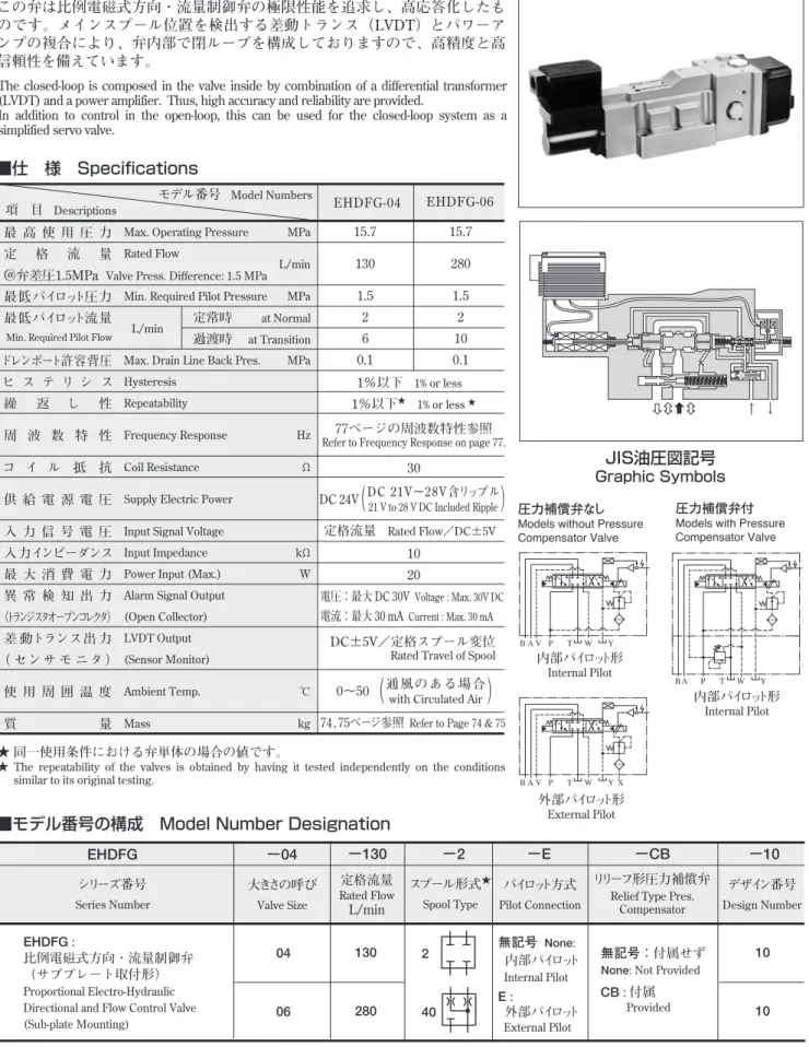
この弁は比例電磁式方向・流量制御弁の極限性能を追求し、高応答化したも
のです。メインスプール位置を検出する差動トランス(LVDT)とパワーア
ンプの複合により、弁内部で閉ループを構成しておりますので、高精度と高
信頼性を備えています。
The closed-loop is composed in the valve inside by combination of a differential transformer
(LVDT) and a power amplifier. Thus, high accuracy and reliability are provided.
In addition to control in the open-loop, this can be used for the closed-loop system as a
simplified servo valve.
■仕 様 Specifications
モデル番号
Model Numbers項 目
DescriptionsEHDFG-04
EHDFG-06
最 高 使 用 圧 力
定
格
流
量
@弁差圧1.5MPa
最低パイロット圧力
最低パイロット流量
ドレンポート許容背圧
ヒ ス テ リ シ ス
繰
返
し
性
周 波 数 特 性
コ イ ル 抵 抗
供 給 電 源 電 圧
入 力 信 号 電 圧
入力インピーダンス
最 大 消 費 電 力
異 常 検 知 出 力
(トランジスタオープンコレクタ)
差 動トランス出 力
( セ ン サ モ ニ タ )
使 用 周 囲 温 度
質
量
Max. Operating Pressure MPa Rated Flow
L/min Min. Required Pilot Pressure MPa
Max. Drain Line Back Pres. MPa Hysteresis
Repeatability
Frequency Response Hz Coil Resistance Ω Supply Electric Power
Input Signal Voltage
Input Impedance kΩ Power Input (Max.) W Alarm Signal Output
(Open Collector) LVDT Output (Sensor Monitor)
Ambient Temp. ℃ Mass kg Min. Required Pilot Flow L/min
定常時
at Normal過渡時
at Transition15.7
130
1.5
2
6
0.1
15.7
280
1.5
2
10
0.1
1%以下
1% or less1%以下
★ 1% or less ★77ページの周波数特性参照
Refer to Frequency Response on page 77.
30
10
20
DC 24V
(
DC 21V∼28V含リップル
)
21 V to 28 V DC Included Ripple定格流量
Rated Flow/DC±5V電圧:最大 DC 30V
Voltage : Max. 30V DC電流:最大 30 mA
Current : Max. 30 mADC±5V/定格スプール変位
Rated Travel of Spool
0∼50
(
通 風 の あ る 場 合
)
with Circulated Air
★ 同一使用条件における弁単体の場合の値です。
★ The repeatability of the valves is obtained by having it tested independently on the conditions similar to its original testing.
■モデル番号の構成 Model Number Designation
EHDFG
−04
−130
−2
−E
−CB
−10
シリーズ番号
Series Number大きさの呼び
Valve Sizeパイロット方式
Pilot Connection内部パイロット形
Internal Pilot内部パイロット形
Internal Pilot外部パイロット形
External Pilotスプール形式
★ Spool Typeリリーフ形圧力補償弁
Relief Type Pres. Compensator
デザイン番号
Design Number定格流量
Rated FlowL/min
EHDFG :
比例電磁式方向・流量制御弁
(サブプレート取付形)
Proportional Electro-Hydraulic Directional and Flow Control Valve (Sub-plate Mounting)無記号:付属せず
None: Not Provided
無記号
None:内部パイロット
Internal Pilot04
06
130
280
10
10
2
40
CB : 付属
ProvidedE :
外部パイロット
External Pilot★スプール形式は中立位置の状態を示します。
★Spool type is shown under the neutral position.JIS油圧図記号
Graphic Symbols
圧力補償弁なし
Models without Pressure Compensator Valve
圧力補償弁付
Models with Pressure Compensator Valve A B V P T W Y A B P T W Y A B V P T W Y X
Valve Press. Difference: 1.5 MPa
■付属品
Attachment
●取付ボルト Mouting Bolts
モデル番号
Model Numbers個数
Q’ty圧力補償弁なし
Models without Pres. Compensator圧力補償弁付
Models with Pres. Compensator六角穴付ボルト
Socket Head Cap ScrewEHDFG-04 EHDFG-06 M6×40 L M10×45 L M12×60 L ― 2 4 6 1式 1 Set M6×120 L M10×125 L ― 取付ボルトキット Mtg. Bolt Kit MBK-06-01-30 DHGM-04-20 DHGM-04X-20 DHGM-06-50 DHGM-06X-50 EHDFG-04 EHDFG-06
■サブプレート
Sub-Plate
弁モデル番号
Valve Model Numbers質 量
Mass kgサブプレート
モ デ ル 番 号
Sub-Plate Model Numbers接 続 口 径
Thread SizeRc
4.4
4.1
7.4
1/
2 3/
4 3/
4 1●サブプレートをご使用の場合は、上記モデル番号にてご注文ください。
なお、サブプレートをご使用にならない場合は弁取付面を6-S程度
に仕上げてください。
●Sub-plates are available. Specify sub-plate model from the table above. When sub-plates are not used, the mounting surface should have a good machined finish.
■Instructions
●Back Pressure to Drain Port
The drain port should be connected directly to the oil tank with a back pressure of not more than 0.1 MPa.
●Installation condition
(Protection from magnetic field of DC SOL)If a DC SOL. is installed near this valve, the magnetic field of DC SOL. may affect the control flow rate. Therefore, install the DC SOL. outside the area shown below.
■使用上の注意
●ドレンポート
背圧が0.1 MPa以下になるようにして、直接油タンクへ接続してく
ださい。
●設置条件(他のDC SOLの磁界からの保護)
本弁の近くにDC SOLを設置する場合は、DC SOL通電時に生ずる
磁界により制御流量に影響を及ぼすことがありますので、下記に
示す領域外に設置してください。
100 50 80 160 トルクモータ側Torque Motor Side
差動トランス側 LVDT Side
EHDFG-04-130-※-※-10
EHDFG-04-130-※-※-CB-10
14.2 34 34.9 1.6 10.1 431 150 130 101.6 90 221 32 4 71.3 69.8 50 141 123 圧力ポート“P” Pressure Port “P” パイロット圧力ポート“X” Pilot Pressure Port “X”内蔵フィルタ取出口 プラグ二面幅 22
Plug for Cartridge Filter, 22 Hex.
2- エアベント 六角穴二面幅 3
Air Vent 3 Hex. Soc. 2 Places
シリンダポート“B” Cylinder Port “B”
シリンダポート“A” Cylinder Port “A”
ドレンポート“Y” Drain Port “Y”
2-φ7 穴、φ11 ざぐり深1 7 Dia. Through 11 Dia. Spotface 4 Places 4-φ11 穴、φ17.5 ざぐり深1
11 Dia. Through 17.5 Dia. Spotface 4 Places
電線管接続口 G1/ 2
Electrical Conduit Connection G1/
2 Thd.
位置決めピン2-φ3 Locating Pin 3 Dia. 2 Places
取付面(Oリング付) Mounting Surface (O-Rings Furnished)
アンプ
端子台詳細は75ページ参照
Amplifier (Refer to Page 75)
タンクポート“T” Tank Port “T”
電源表示灯 Power Indicator Lamp
★外部パイロット形を内部パイロット形に変え
る場合はこのプラグの奥にあるもう1つのプラ
グを取り外してください。
★For alternation of model from external pilot pressure to internal pilot pressure, take out another inner screw plug behind this plug.
★
質量
Mass……… 10.5 kg
75
シリーズ
シリーズ高応答形比例電磁式方向・流量制御弁
EHDFG-06-280-※-※-10
EHDFG-06-280-※-※-CB-10
15.8 53.2 13 77 484 147 186 130.2 118 92.1 46 236 6 41 151 133 圧力ポート“P” Pressure Port “P” パイロット圧力ポート“X” Pilot Pressure Port “X”ドレンポート“Y” Drain Port “Y”
タンクポート“T” Tank Port “T” 電源表示灯 Power Indicator Lamp シリンダポート“B” Cylinder Port “B” シリンダポート“A” Cylinder Port “A”
6-φ13.5 穴、φ20 ざぐり 13.5 Dia. Through 20 Dia. Spotface 6 Places
内蔵フィルタ取出口プラグ二面幅 22
Plug for Cartridge Filter, 22 Hex.
2- エアベント 六角穴二面幅 3
Air Vent 3 Hex. Socket 2 Places
電線管接続口 G1/ 2
Electrical Conduit Connection G1/
2 Thd.
★
位置決めピン2-φ6 Locating Pin 6 Dia. 2 Places
取付面(Oリング付) Mounting Surface (O-Rings Furnished)
★外部パイロット形を内部パイロット形に変え
る場合はこのプラグの奥にあるもう1つのプラ
グを取り外してください。
★For alternation of model from external pilot pressure to internal pilot pressure, take out another inner screw plug behind this plug.
■アンプ部 Detail of Amplifier
●端子台詳細 Connecting Terminal
●接続説明図 Circuit Schematic
★ DITHER/GAIN
出荷時、最適に調整済みですから、そのままご使用いただけ
ます。(通常では操作しないでください。)
★ DITHER / GAINUse as they are since they are factory-preset to the optimum position. (Do not touch them in normal condition.)
★1 For “SM” terminal, external instruments should have input impedance of more than 10 kΩ.
★2 For “CH” terminal, external instruments should have input impedance of more than 10 kΩ.
★3 Use shielded cable for “Input” connection.
The ground of shielded cable must be connected to input signal side.
★1 SM端子は、入力インピーダンス10kΩ以上でご使用ください。
★2 CHは、
入力インピーダンス10kΩ以上の計測器をご使用ください。
★3 入力信号線は、シールド線をご使用ください。
なお、シールド線の接地は信号発生源側で行ってください。
ALARM SENSOR OSC +24 V −24 V GAIN CH DITHER 0 C IN 入力★3 ★2 2.2Ω ALARM SIG ALARM COM SM ★1記 号
Terminal端子名称
Name IN C SM ALARM SIG COM −24V 0V 24V CH 入力信号(±) Input Signal (±) 入力信号(COM) Input Signal (COM) センサモニタ出力(C間) Sensor Monitor (to C) 異常検知出力 Alarm Output供給電源 Power Supply
SOL.電流チェック端子(C間) Output Current Check (to C)
★ ★
アンプ
端子台詳細は下記参照
Amplifier (Refer to below)
質量
Mass……… 18.5 kg
質量
Mass……… 29.6 kg
Input
T P X B A Y Y B A X P T 12 32.2 18.3 14.2 36 20 19 21.5 29 16 10.1 12 13.1 14.2 1.6 190 166 101.6 76.7 50 34 57.1 90 65.8 88.1 130 120 96 71.4 69.8 55.6 65 125 90 46 33 76 58 102 137.5
■サブプレート Sub-Plate
DHGM-04、04X
2-φ6 穴 6 Dia. 2 Places 4-M10 ねじ深 17 M10 Thd. 17 Deep 4 Places 2-M6 ねじ深 12 M6 Thd. 12 Deep 2 Places 4-φ17.5 穴 17.5 Dia. 4 Places 2-φ3.6 穴深 5 3.6 Dia. 5 Deep 2 Places 4-φ11穴、φ17.5ざぐり 11 Dia. Through 17.5 Dia. Spotface 4 Places4-Rc“D” Rc “D” Thd. 4 Places 2-Rc1/ 4 Rc1/ 4 Thd. 2 Places
モデル番号
Model Numbers DHGM-04-20 DHGM-04X-20 1/
2 3/
4D
17.5 29.5 12.5 12 25 29.4 12 19.1 17.5 5.6 P T X V W A B Y 204 180 130.2 112.7 94.5 77 53.2 73.1 46.1 96.9 100.8 126.2 156 116 92.1 74.6 34 35 50DHGM-06、06X
6-M12 ねじ深 24 M12 Thd. 24 Deep 6 Places 2-φ7 穴深 8 7 Dia. 8 Deep 2 Places4-φ11穴、 Rc1/ 4(裏面) 11 Dia. Rc1/ 4 Thd. (Rear Side) 4 Places 4-φ11 穴、φ17.5ざぐり 11 Dia. Through 17.5 Dia. Spotface 4 Places 4-φ23穴、 Rc“D”(裏面) 23 Dia. Rc “D” Thd. (Rear Side) 4 Places
モデル番号
Model Numbers DHGM-06-50 DHGM-06X-50 3/
4 1D
77
シリーズ
シリーズ高応答形比例電磁式方向・流量制御弁
■入力信号電圧−流量特性 Input Signal Voltage vs. Flow
■供給圧力−流量特性 Differential Pressure vs. Metered Flow
■周波数応答特性 Frequency Response
(スプール変位
Travel of Spool)
粘度
Viscosity: 30 mm
2/s
弁差圧
Valve Pressure Difference: 1.5 MPa 一定
Const.粘度
Viscosity: 30 mm
2/s
■ステップ応答特性(例) Step Response
本特性は弁単体で計測したものです。したがって、それぞれの回路により特性が異なります。
The step responses below are those obtained when the valve itself is tested independently.
The step responses may differ from them when the valve is used in combination with other control valves.
EHDFG-04
A B P T A B P T −5 −4 −3 −2 −1 150 100 50 流 量 Flow Rate L/min 0 1 2 3 4 5 50 100 150 入力信号電圧 V DC Input Signal VoltageEHDFG-06
A B P T A B P T −5 −4 −3 −2 −1 流 量 Flow Rate L/min 0 1 2 3 4 5 100 200 300 300 200 100EHDFG-04
A B P T A B P T 300 250 200 150 100 50 50 100 150 200 250 300 流 量 Flow Rate L/min 5.9 3.9 2.0 2.0 3.9 5.9 0 弁差圧 MPa Valve Pressure Difference −2V −3V −4V −5V +2V +3V +4V +5VEHDFG-06
A B P T A B P T 600 500 400 300 200 100 100 200 300 400 500 600 流 量 Flow Rate L/min 5.9 3.9 2.0 2.0 3.9 5.9 0 −2V −3V −4V −5V +2V +3V +4V +5VEHDFG-04
0 −20 −40 −60 −80 −100 −120 −140 −160 −180 0 −10 −20 −30 位 相 (度)Phase (deg) ゲ イ ン (dB) Gain 2 5 1 10 20 50 100 200 位相 Phase ゲイン Gain周波数
Frequency(
Hz)
モ デ ル 番 号 Model Number :EHDFG-04-130-2-E-10 粘 度 Viscosity :30 mm2/s
パイロット圧力 Pilot Pressure :15.7 MPa スプール変位 Travel of Spool :定格の±10%
±10% of Rated Travel
モ デ ル 番 号 Model Number :EHDFG-06-280-2-E-10 粘 度 Viscosity :30 mm2/s
パイロット圧力 Pilot Pressure :15.7 MPa スプール変位 Travel of Spool :定格の±10% ±10% of Rated Travel