Synchronization in Small-World Chaotic Circuit Network under Parameter Mismatch
Kenta Ago
Dept. of Electrical and Electronic Eng., Tokushima University
2-1 Minami-Josanjima, Tokushima 770–8506, Japan Email: [email protected]
Yoko Uwate
Dept. of Electrical and Electronic Eng., Tokushima University
2-1 Minami-Josanjima, Tokushima 770–8506, Japan Email: [email protected]
Yoshifumi Nishio
Dept. of Electrical and Electronic Eng., Tokushima University
2-1 Minami-Josanjima, Tokushima 770–8506, Japan Email: [email protected]
Abstract—In this study, we investigate the synchronization of coupled chaotic circuits in the presence of parameter mismatch.
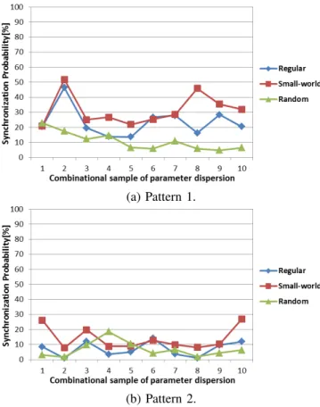
We consider three different network topologies obtained from the small-world network model and two parameter dispersions of mismatched circuits. By means of the computer calculations, the synchronization probabilities of the entire network are investigated during a certain time interval. From the simulation results, we find that the small-world network provides the best framework to realize synchronization.
I. I NTRODUCTION
Complex networks have attracted a great deal of attention from various fields since the discovery of “small-world”
network [1] and “scale-free” network [2]. In particular, how network topological structure influences its dynamical behav- iors, is a significant hot topic. In order to apply for practical applications in many disciplines, understanding the relation- ship between topological structure and functional behavior on the networks can be considered as an important problem.
As the dynamics on the networks, the synchronization is one of the fundamental phenomenon in various fields. Especially, chaotic synchronization is very interesting phenomenon, have received a great deal of attention since the report by Pecora and Carrol [3]. However, there are not many studies for complex networks of continuous-time real physical systems such as electrical circuits. In our previous work, we have investigated the synchronization phenomena of coupled chaotic circuits on a complex network with local bridge [4]. We have focused on local bridge structure observed from the small-world network.
However, the circuit parameters were fixed with same param- eters for all chaotic circuits and the only one network model was considered.
In this study, we investigate the global synchronization of coupled chaotic circuits in the small-world network. Wan and Chen reported the synchronization in the small-world coupled Chua’s circuits [5]. We focus on the parameter mismatches, the synchronization of coupled chaotic circuits in three different network topologies obtained from the small-world network model is studied. From the simulation results, synchronization probability during a certain time interval are compared among three network topologies. Thereby, the small-world topology
(a)
9 10 11 12 13 14 15
16
17 18
19 20
1
2
3
4
5
6 7
8 9
10 11 12 13 14 15
16
17 18
19 20
1
2
3
4
5
6 7
8 9
10 11 12 13 14 15
16
17 18
19 20
1
2
3
4
5
6 7 8
(b) (c)
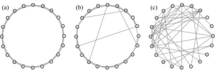
Fig. 1. Illustration of the WS model for N = 20 and k = 4. (a) : Regular network, p = 0. (b) : Small-world network, p = 0.1. (c) : Random network, p = 1.
is shown to be effective for the achievement of the synchro- nization in the entire network. 1
II. S MALL -W ORLD N ETWORK M ODEL
In 1998, Watts and Strogatz introduced very interesting small-world network model, called the WS model [1]. The WS model can be generated as shown in Fig. 1. Starting from a ring lattice with N nodes and k edges per nodes in Fig. 1(a), each edge is rewired at randomly with probability p.
By increasing the probability p, the randomness of the network are also increased. The small-world network is known as the graph which is characterized by highly clustering coefficient like a regular graph and small path length like a random graph.
Topological structures in complex networks of N nodes and E edges can be evaluated by the typical three structural metrics (degree, clustering coefficient and path length). First, degree (k) shows the number of edges on a node. Second, clustering coefficient (C ) shows the number of actual links between neighbors of a node divided by the number of possible links between those neighbors. This is given as follows:
C = 1 N
∑ N n=1
C n = 1 N
∑ N n=1
2E n
k n (k n − 1) . (1)
1 We have already presented this result in Proc. of NOLTA’15, pp. 431-444, Dec. 2015.
- 15 -
IEEE Workshop on Nonlinear Circuit Networks
December 11-12, 2015
TABLE I
P ROPERTIES OF THREE NETWORKS AS SHOWN IN F IG . 1.
Regular Small-world Random
p 0 0.1 1
C 0.500 0.358 0.216
L 2.895 2.458 2.221
Third, path length (L) shows the shortest path in the network between two nodes. This is given as follows:
L = 2
N (N − 1)
N ∑ −1 m=1
∑ N n=m+1
l(m, n). (2)
In this research, we consider coupled chaotic circuits in three different network topologies obtained from the WS model in Fig. 1. Each topologies is called regular, small- world and random networks, respectively. Table 1 shows the properties of three networks as shown in Fig. 1.
III. C OUPLED C HAOTIC C IRCUIT
Figure 2 shows the chaotic circuit which is three- dimensional autonomous circuit proposed by Shinriki et al. [6][7]. This circuit is composed by an inductor, a negative resistor, two capacitors, and dual-directional diodes. In this study, we propose 20 coupled chaotic circuits in three network topologies as shown in Fig. 1. In these network models, chaotic circuits are applied to each node of the networks and each edge corresponds to a coupling resistor R.
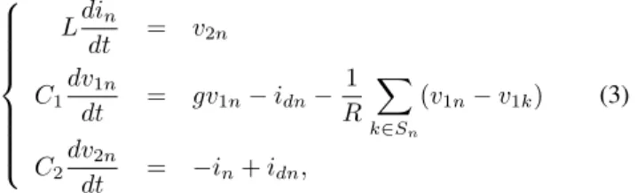
First, the circuit equations are given as follows:
L di n
dt = v 2n
C 1
dv 1n
dt = gv 1n − i dn − 1 R
∑
k∈S n
(v 1n − v 1k )
C 2
dv 2n
dt = − i n + i dn ,
(3)
where n = 1, 2, 3, ..., 20 and S n is the set of nodes which are directly connected to the node n. We approximate the i − v characteristics of the nonlinear resistor consisting of the diodes by the following three-segment piecewise-linear function:
i dn =
G d (v 1n − v 2n − V ) (v 1n − v 2n > V ) 0 ( | v 1n − v 2n | ≤ V ) G d (v 1n − v 2n + V ) (v 1n − v 2n < − V ).
(4)
By using the parameters and the variables:
i n =
√ C 2
L V x n , v 1n = V y n , v 2n = V z n
t = √
LC 2 τ, “ · ” = d
dτ , α = C 2
C 1
β =
√ L C 2
G d , γ =
√ L C 2
g, δ = 1 R
√ L C 2
,
(5)
- g
v 2n
n L
v 1n
i dn i n
C 1 C 2
Fig. 2. Chaotic circuit.
y
z
1.5
1.5 -1.5
-1.5
y
z
1.5
1.5 -1.5
-1.5
y
z
1.5
1.5 -1.5
-1.5
(a) (b) (c)
Fig. 3. Chaotic attractor of the circuit as shown in Fig. 2. β = 20, γ = 0.5.
(a) : α = 0.46, (b) : α = 0.50, (c) : α = 0.54,
the normalized circuit equations are given as follows:
˙
x n = z n
˙
y n = αγy n − αf (y n − z n ) − αδ ∑
k ∈ S n
(y n − y k )
˙
z n = f (y n − z n ) − x n .
(6)
The nonlinear function f (y n − z n ) corresponds to the i − v characteristics of the nonlinear resistor consisting of the diodes and are described as follows:
f (y n − z n ) =
β(y n − z n − 1) (y n − z n > 1) 0 ( | y n − z n | ≤ 1) β(y n − z n + 1) (y n − z n < − 1).
(7)
This circuit generates asymmetric chaotic attractor as shown in Fig. 3. The values y and z in Fig. 3 correspond to v 1 and v 2
of the circuit in Fig. 2, respectively. By increasing parameter α, the range of chaotic trajectory becomes widely formed.
IV. P ARAMETER D ISPERSION
In this research, we fix the circuit parameters as α = 0.50, β = 20, γ = 0.50 and δ = 0.70 for all chaotic circuits.
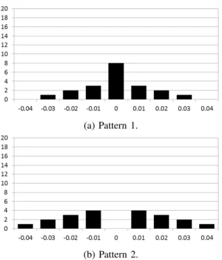
Additionally, the parameter mismatches ∆α are added for each circuit parameter α which relate to the chaos degree. Namely, the parameter α of each circuit is shown as α = 0.5 + ∆α, respectively. We propose the parameter dispersion as shown in Fig. 4. Each pattern is different in the number of the parameter mismatched circuits and the range of the param- eter mismatches. By using the proposed parameter dispersion patterns, we add the parameter mismatches for the circuits in the computer simulations.
- 16 -
(a) Pattern 1.
(b) Pattern 2.
Fig. 4. Proposed two patterns of the parameter dispersion. Vertical axis: the number of circuits. Horizontal axis: parameter mismatches ∆α.
0.10
-0.10 0 0.01
-0.01
y 1 - y 2
(a) Nodes 1 and 2.
0.10
-0.10 0 0.01
-0.01