九州大学学術情報リポジトリ
Kyushu University Institutional Repository
Research of Lithium Ion Batteries Based on Lithium/Copper(Ⅱ) Chloride
橋﨑, 克雄
http://hdl.handle.net/2324/2236268
出版情報:九州大学, 2018, 博士(工学), 課程博士 バージョン:
権利関係:
Research on Lithium Ion Batteries Based on Lithium/Copper (II) Chloride
A thesis submitted to Institute for Materials Chemistry and Engineering Kyushu University for the degree of Doctor of Science
March 2019
by
Katsuo Hashizaki
i
Abstract
This study summarizes the state of research on Li/CuCl2 batteries, one of the high-capacity transition-metal conversion-type lithium ion batteries that have been developed as promising substitutes for conventional intercalation-type lithium ion batteries.
It is also shown that Li can potentially be stored in a Cu/LiCl/C composite electrode through the reformation of a re-conversion reaction; such a cathode would have several times the capacity with a graphite anode and would be safer than a conventional intercalation-type lithium ion battery. However, there are two major barriers to developing such a cathode:
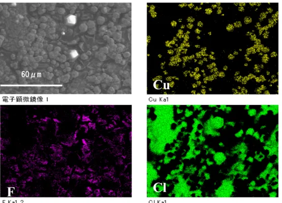
First, CuCl2 used as the active material in the cathode electrode readily dissolves in the organic solvent, which can easily induce self-discharge. To address this problem, a solvent can be applied to combine an electrolyte with a lithium salt to produce a dissolution-inhibiting effect through the formation of an insoluble, low dielectric constant film on the surface of the cathode active material. In this study, it was shown that dissolution of CuCl2, the cathode active material, in the electrolyte is suppressed through the use of methyl difluoroacetate (MFA) as the organic solvent and lithium hexafluorophosphate (LiPF6) as the lithium salt.
Second, in cases inchloride ions are present in the electrolyte, generating CuCl2 is difficult because the disproportionation reaction of Cu is occurred, and CuCl is nonconductive intermediate reactant. It was determined that CuCl2 generation can be maintained in such cases by controlling the chloride ion concentration in the electrochemical reaction field of the cathode electrode.
In particular, this involves the instigation of a reversible reaction of CuCl2
through the mixing of activated carbon as the added carbon of the cathode and controlling the chlorine ion concentration in the electrochemical reaction field using micro-pores. Thermodynamic data confirmed that this phenomenon is highly correlated with the pCl diagram.
Given robust solutions to these two problems, the prospects for the development of high-capacity, safe Li/CuCl2 batteries appear to be promising.
ii
Contents
1
Chapter 1 General Introduction
... - 1 -1.1 Background of Research ... - 1 -
1.2 Characteristics of Lithium Ion Batteries ... - 2 -
1.2.1 Intercalation-type Lithium Ion Batteries ... - 2 -
1.2.2 Conversion-type Lithium Ion Batteries ... - 3 -
1.3 Types of Conversion-type Lithium Ion Batteries and Their Features ... - 5 -
1.3.1 Selection of Transition-Metal and Anion Element ... - 5 -
1.3.2 Transition-Metal Fluorides ... - 7 -
1.3.3 Transition-Metal Oxides ... - 9 -
1.3.4 Transition-Metal Sulfides ... - 12 -
1.3.5 Transition-Metal Chlorides ... - 14 -
1.4 Copper (II) Chloride-based Lithium Ion Batteries and Their Features ... - 17 -
1.4.1 Solubility of Copper (II) Chloride in Organic Solvent ... - 17 -
1.4.2 Suppression of Copper (II) Chloride Solubility in Organic Solvents ... - 21 -
1.4.3 Electrochemical Reactions of Li/CuCl2 Batteries ... - 25 -
1.5 Research Purpose and Implementation Items ... - 28 -
References ... - 32 -
2
Chapter 2 Optimization of Organic Solvent
... - 37 -2.1 Introduction ... - 37 -
2.2 Experimental for Optimization of Organic Solvents ... - 37 -
2.3 Experimental Results for Organic Solvents ... - 39 -
2.3.1 Evaluation of Discharge Test Results on PC ... - 39 -
2.3.2 Evaluation of Discharge Test Results on EC+DMC+EMC ... - 40 -
2.3.3 Evaluation of Discharge Test Results on TFPC ... - 41 -
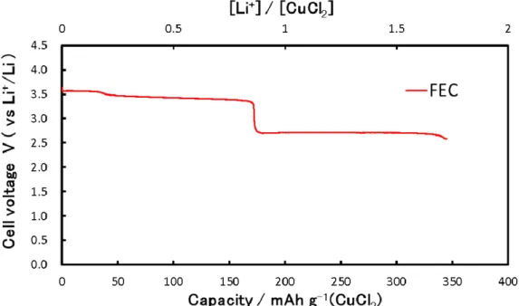
2.3.4 Evaluation of Discharge Test Results on FEC ... - 42 -
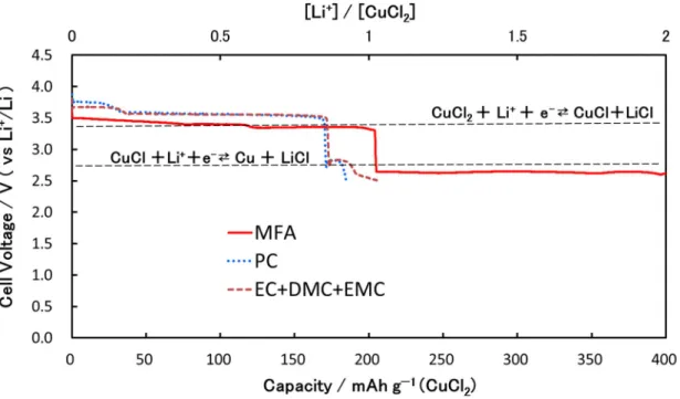
2.3.5 Evaluation of Discharge Test Results on MFA ... - 43 -
2.4 Summary ... - 48 -
References ... - 49 -
3
Chapter 3 Optimization of Lithium Salt and Reaction Analysis
... - 50 -3.1 Introduction ... - 50 -
3.2 Experimental for Optimization of Lithium Salts ... - 50 -
3.3 Experimental Results for Lithium Salts ... - 51 -
3.3.1 Evaluation of Self-Discharge Test Results on LiBETI ... - 51 -
3.3.2 Evaluation of Self-Discharge Test Results on LiTFSI ... - 54 -
iii
3.3.3 Evaluation of Self-Discharge Test Results on LiPF6 ... - 56 -
3.3.4 Suppression Mechanism of Copper (II) Chloride Dissolution ... - 59 -
3.3.5 Influence of LiPF6 Concentrations on Ionic Conductivity ... - 68 -
3.3.6 Influence of LiPF6 Concentration on Discharge and Charge Properties ... - 69 -
3.3.7 Correlation of Copper Dissolution and Battery Performance ... - 70 -
3.4 Reaction Analysis of Li/CuCl2 Batteries Based on Conversion Reaction with LiPF6/MFA Electrolyte ... - 71 -
3.4.1 Analysis Methods ... - 71 -
3.4.2 Discharge and Charge Reaction Analysis of CuCl2 Electrode Using XAFS... - 71 -
3.5 Summary ... - 75 -
References ... - 76 -
4
Chapter 4 Cycling Performance of Li/CuCl
2Batteries Based on Conversion Reaction
... - 77 -4.1 Introduction ... - 77 -
4.2 Results of Discharge and Charge Cycling Testing on CuCl2 Electrode with LiPF6/MFA ... - 78 -
4.2.1 Discharge and Charge Cycling Test Results at Upper Limit Charge Voltage of 3.6 V ... - 78 -
4.2.2 Influence of Upper Limit Charge Voltage ... - 79 -
4.3 Consideration of Electrochemical Reactions for Li/CuCl2 Batteries ... - 85 -
4.4 Summary ... - 87 -
References ... - 87 -
5
Chapter 5 Cycling Performance of Li/CuCl
2Batteries Based on Re-conversion Reaction
... - 88 -5.1 Introduction ... - 88 -
5.2 Experimental for Li/CuCl2 Batteries Based on Re-conversion Reaction ... - 89 -
5.3 Experimental Results for Li/CuCl2 Batteries Based on Re-conversion Reaction ... - 91 -
5.3.1 Preliminary Evaluation of Cu/LiCl/AB Composite Electrode ... - 91 -
5.3.2 Cyclic Voltammetry Properties of Cu/LiCl Composite Electrode ... - 94 -
5.3.3 Cycling Results of Cu/LiCl Composite Electrode ... - 97 -
5.3.4 Cycling Results of Cu/LiCl/C (Glassy Carbon) ... - 105 -
5.3.5 Cycling Results Cu/LiCl/C (Activated Carbon) ... - 109 -
5.3.6 Reaction Analysis of Charge and Discharge Properties ... - 119 -
5.3.7 Influence of Additive Carbon Properties on Charge and Discharge Properties ... - 124 -
5.4 Summary ... - 125 -
6
Chapter 6 Generalization
... - 127 -6.1 Summarization ... - 127 -
iv
Acknowledgments ... - 128 - Appendix ... - 129 - Properties of Additive Carbon ... - 129 -
- 1 -
1
Chapter 1 General Introduction
1.1 Background of Research
Because electric energy is difficult to store, power distribution systems must generally rely on the synchronization of power supplied by the plant with consumer demand. This balancing requirement has impeded the introduction of renewable energy sources such as photovoltaic and wind power generation that can reduce CO2 emissions because the output of such sources is unstable and therefore cannot perform the above-mentioned synchronization. The intermittency of renewable energy has led to a considerable amount of research on developing large-scale electric power-storage systems equipped with batteries for stabilizing power output and storing electric power.
Owing to their superior responsiveness, small size, and light weight, lithium ion batteries (LIBs) represent a promising medium for use in power-storage systems and are becoming popular household power-storage devices. However, further dissemination of LIBs will require a reduction in their current cost by approximately one third through, e.g., increased energy density. Furthermore, adapting LIBs for use in portable consumer electronic devices (such as mobile phones and laptop computers), hybrid vehicles (HEVs), plug-in hybrid vehicles, and pure electric vehicles will require increased energy density, output, and safety along with decreased costs. It is estimated that the widespread adoption of LIBs or commercial devices and vehicle use will require an increase in energy density by a factor of three to five.1
An increase in the energy density of LIBs can theoretically be achieved by adopting high-voltage, high-capacity cathode active materials and/or high-capacity anode active materials. However, because the energy density of “conventional” LIBs is already approaching the limits of materials that apply the “intercalation and de-intercalation mechanisms” of lithium ions for maintaining host structures, it is imperative to develop
“new concept” high-energy-density LIBs. The energy densities of conventional LIBs are restricted by the exchange number of the lithium ions in the cathode active materials and by the stability of such host structures.2,3
In this study, the use of cathode active materials using conversion and re-conversion reaction mechanisms as a replacement for conventional intercalation and de-intercalation materials was investigated as a pathway to developing a “new concept”
LIB with enhanced energy density.
- 2 -
1.2 Characteristics of Lithium Ion Batteries
LIBs can be roughly classified into two types: “conventional” batteries based on the intercalation reaction, which are currently widely used; and “new concept” batteries based on conversion reactions.
Intercalation-type LIBs use transition-metal oxides, which generally contain lithium metals such as LiNiO2 or LiCoO2, as the cathode active material and carbon such as graphite as the anode active material. LIBs in practical current use generally have energy densities ranging from 100 to 150 Wh kg−1 and operating in the 4.0 V range.
In recent years, conversion-type LIBs with large charge/discharge capacities have begun to appear. These devices feature cathode active material that take advantage of a newly discovered reaction mechanism 4,5 based on the reversible reactivity of nanosized metal particles of transition-metal compounds.
1.2.1 Intercalation-type Lithium Ion Batteries
The operating principle of intercalation-type LIBs is illustrated in Figure 1-1. Using LiCoO2 as an example of a typical cathode active material, a two-dimensional (2D) layered sheet of CoO2 octahedrons is used to form the skeleton of a crystal structure with lithium ions deposited into the gaps. During charging and discharging, the lithium ions migrate through and maintain the layered, 2D CoO2 structure in a so-called intercalation reaction.
Table 1-1 lists examples of intercalation-type LIBs. The general electrochemical reaction formula of a “conventional” intercalation-type LIB is given as
yC + LiMXz ⇄ LixCy + Li(1 − x)MXz [1-1]
C = Carbon
M = Transition metal (Co, Ni, Mn, etc. ) X = Anion (F, O, S, N, etc.)
Z = The number of anion
In these reactions, lithium ions do not participate in the transfer of electrons, and the transition metals (such as Co, Ni, and Mn) that comprise the host lattice are redoxed to maintain the charge neutrality of the electrode. Such transition metals that are capable of performing redox are indispensable constituent elements of LIBs, and the number of lithium ion sites that the transition metal can provide in the intercalation reaction is the primary factor determining the capacity of the LIB. For example, theoretically each LiCoO2 provides one lithium ion site for the production of CoO2; in practice, however, the number of sites is reduced to 60%–70% to maintain the layered CoO2 structure. In
- 3 -
the graphite (C) anode, each C6 hosts one lithium ion site.
In this process, intercalation reaction-type LIBs maintain a capacity of ~ 200mAh g−1 because lithium ions migrate into and out the transition-metal crystal structure within the range that the structure does not collapse.6,7
Figure 1-1. Operational principle of intercalation-type lithium ion battery. Lithium ions migrate into and out of the structure via the electrolyte between the anode and cathode electrodes during charging and discharging.
Table 1-1. Examples of intercalation-type lithium ion batteries.
Battery
system Electrochemical reaction equation
Av.
Potential
(V)
Theoretical Capacity
(mAh g−1)
C6/LiCoO2 Li0.5CoO2+0.5Li++0.5e− ⇄ LiCoO2 3.6 137 C6/LiNiO2 Li0.3NiO2+0.7Li++0.7e− ⇄ LiNiO2 3.5 193
C6/LiMn2O4 Mn2O4+Li++e− ⇄ LiMn2O4 3.8 148
1.2.2 Conversion-type Lithium Ion Batteries
A ‘‘conversion reaction’’ is generally defined as a reaction in which a binary transition-metal compound reacts with lithium to generate a simple transition-metal substance and a binary lithium compound. This reaction involves the complete reduction of a transition metal to a metallic state through a process involving large numbers of electrons and is therefore suited to the development of extremely high-capacity batteries.
The general electrochemical reaction formula of “new concept” conversion-type LIBs is given as
Charge
LiMXz
Discharge
Li+ Li+
Li(1-x)Mz e-
e- LiMXz
- 4 -
MaXb + nbLi+ + nbe− ⇄ bLinX + aM [1-2]
M = Transition metal (Cu, Ni, Co, Fe, Mn, V, Ti, etc.) X = Anion (F, O, S, Cl, etc.)
N = The formal oxidation state of X (n = 1 ~ 3).
One of the advantages of conversion-type LIBs is their superior rating capabilities relative to intercalation-type LIBs. Another attractive feature is a general increase in M-X bond ionicity, which is associated through the convergence reaction in [1-2] above with an increased output voltage that can be tuned continuously from 0 to 3.0 V by modifying the anion X. As will be discussed in the next section, the highest potential is attained using transition-metal fluorides. The wide voltage range of such conversion-type LIBs requires further investigation.
Figure 1-2 shows a conversion-type LIB using a representative cathode material.
The types of cathode materials used in conversion-type LIBs are discussed in the next section.
Figure 1-2. Operational principle of conversion-type lithium ion battery.
The key to the reversibility of conversion-type LIBs seems to be the complete oxidation and reduction of the transition metal and subsequent formation of nanosized metal particles that are well dispersed within a lithium binary compound (LinX) matrix. The breaking characteristics of make these LinX bonds are sensitive to the nature of the anion, X; in general, LinX is a relatively stable ionic compound with bonds that are generally difficult to break by transition metals to form MaXb. However, improvements in the dynamics and thermodynamic constraints of the transition metal through the
Charge Discharge
Li+ Li+
Li+
Li+
Li+ Li+
e-
e- e-
e- e-
MaXb bLinX+aM MaXb
e-
- 5 -
nanosizing of particles helps to promote the formation of MaXb and the decomposition of LinX via new electrochemical reaction mechanisms based on nanoparticle-sized effects.8,9,10
1.3 Types of Conversion-type Lithium Ion Batteries and Their Features
In this section, a variety of conversion-type LIBs, transition-metal fluorides, sulfides, oxides, and chlorides with lithium in non-aqueous lithium cells that can operate over a wide voltage range (0.02–4.3 V) at room temperature are discussed. Following the recognition of their high reversibility and cycling ability in 2000, increasing attention has been paid to the study of materials that can be used in conversion-type LIBs.111.3.1 Selection of Transition-Metal and Anion Element
In most cases, lithium ion uptake occurs via a heterogeneous reaction based on the transformation of a MaXb (refer equation [1-2]) containing a transition-metal element belonging to group Ⅳ and a non-metallic element belonging to groups ⅥA or ⅦA.
Typical transition metals (M) candidates for use in conversion-type LIBs include Cu, Ni, Co, Fe, Mn, V, and Ti, while typical anion elements (X) include F, O, S, and Cl.
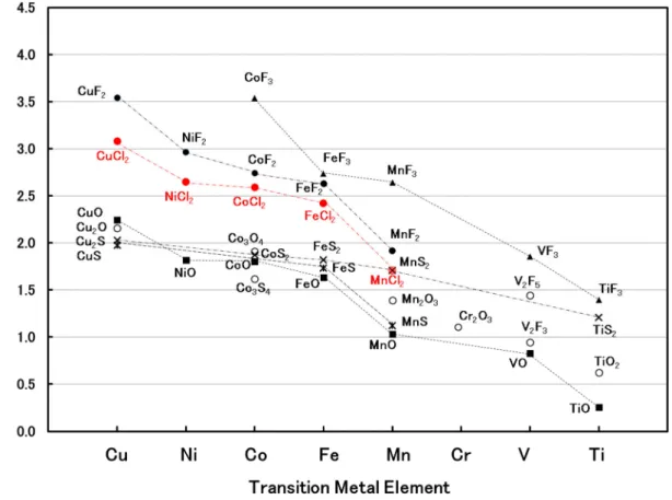
The theoretical potential (voltage) is calculated from the Gibbs free energies of formation (⊿fG) of LinX and the initial compound MaXb following the Nernst equation.
The calculated results for candidate conversion reaction materials are shown in Figure 1-3; all calculated potentials are above 0 V, indicating that all of the candidate materials can undergo the reaction thermodynamically.
⊿G = b⊿fG(LinX) - (⊿fG(MaXb) + nb⊿fG(Li+)) = -nbEF [1-3]
F:Faraday constant (96,485 C mol−1 = 26.8 Ah mol−1) E:Potential (Voltage)(V)
⊿G: Difference between Gibbs free energies before and after the reaction (kJ mol−1)
Here, the Gibbs free energy data were obtained from an electrical science handbook.12 Figure 1-3 shows an increasing trend in the potential with the atomic number of the transition metal, corresponding to a stochiometric and oxidation state from Ti to Cu.
The potential of an electrochemical reaction increases with the ionicity of the M–X bond, and, with the exception of fluorides and chlorides, such bonds have a potential of between 0.5 and 2.0 V (vs Li+/Li).
- 6 -
Figure 1-3. Theoretical voltage calculated from Gibbs free energy of formation (⊿fG) for conversion-type lithium ion batteries.
Because the transition-metal fluorides and chlorides react at significantly high potentials (close to 3.0 V) they are useful as cathode electrode materials. Although transition-metal fluorides are preferred as cathode electrode materials owing to their low equivalent weights and potential, LiF, the reaction product in the discharge process, is insoluble in most organic solvents, which causes a disadvantage in terms of reversibility and rate properties. Similarly, the transition-metal chlorides have a disadvantage in terms of self-discharge and their excessive solubility in most organic solvents. To address these problems, significant research has gone into developing nanoparticles, film materials, etc. to improve the organic solubility of transition-metal fluorides and into mesoporous carbon mixing methods for transition-metal chlorides.13
Previous electrochemical studies of transition-metal fluorides, sulfides, oxides, and chlorides for applications in conversion-type LIBs are discussed in the next sections.
- 7 -
1.3.2 Transition-Metal Fluorides
The conversion reactions of transition-metal fluorides produce lithium fluoride (LiF) and M (metal). For these materials, the conversion reaction equation [1-2] can be rewritten as
MFb + bLi + be− ⇄ bLiF + M [1-4]
M = Transition metal (Cu, Ni, Co, Fe, Mn, V, Ti, etc.)
The Gibbs free energy, potential, theoretical capacity, and energy density for each transition-metal fluoride is shown in Table 1-2. In conversion reactions with lithium, transition-metal fluorides produce a higher potential (≥2.0 V) than other transition-metal compounds, a result of the very high ionic bonding nature of the M-F bond. Attempts have been made to use this material property in intercalation reactions and to use develop cathode active materials using transition-metal fluorides.
Arai et al. reported in 1997 that TiF3, VF3, and FeF3 exhibit average voltages of 2.5, 2.2, and 3.0 V, respectively. Formation of LixMF3 (M = Fe, Ti, V) in similar layered structures resulted in materials with charge/discharge capacities of about 80 mAh g−1.14 Addition of mechanically milled FeF3/C nanocomposites with diameters on the order of 1–20 nm to minimize the length of ion diffusion path improved the specific capacities to 200 mAh g−1 within the potential region of 2.8–3.5 V,15 and a subsequent increase in the operating temperature to 70°C improved the capacities to 660 mAh g−1 within the potential region 1.5–4.5 V.16 Recently, the low-temperature synthesis of a nanostructured iron-based fluoride cathode without carbon through the use of ionic liquids was reported; in the voltage range 1.6–4.5 V, this material had a specific capacity of about 150 mAh g−1 at room temperature.17 Further studies have reported the enhancing the lithium storage capacity of FeF3 by introducing C@LiF, improvement of cycling performance of FeF3 with boron-based addities.18,19
Another transition metal—ball-milling-prepared carbon-coated nano-CuF2—has also been reported.20 Its reaction mechanism, which reportedly involves the transportation of F− from the Cu/CuF2 interface to the CuF2/LiF/electrolyte interface, is important because electron tunneling during the reaction process can result in the formation of Cu nuclei that are not directly located on the Cu/carbon interface.
Powder-based cathodes containing the carbon-coated nano-CuF2 (CCN-CuF2) and carbon black (Ketchen Black) have been prepared by ball-milling methods, and investigated by galvanostatic cycling.21 This electrode exhibits three or four shorter plateaus in discharge and charge profiles, and this is because the Cu dissolution is associated with the consumption of LiF phase in the first charge, and this dissolution
- 8 -
process consequently prevents Cu and LiF from generating to CuF2. As the results, the maximum specific capacity, 316 mAh g−1, is only observed at first cycle, eventually, a significant capacity reduction after the second cycle has been caused.
Based on the above discussion, FeF3 and FeF2 can be considered representative transition-metal fluoride cathode materials for use in conversion reactions that yield very high specific capacities within an attractive voltage range. One of the disadvantages of batteries using conventional anode electrodes such as graphite, however, is finding a method for storing lithium. It has been suggested that LiF-Fe nanocomposites can be used as charge-inducing materials; however, the low conductivity of these compounds must be compensated through the addition of carbon to form a nanocomposite. An electrode composed of one such nanocomposite, a binder-free Fe/LiF/C generated by the pyrolysis of a ferrocene and a LiF mixture, was found to have a reversible specific capacity of 230 mAh g−1 (1.3–4.3 V)22 demonstrating the importance of using a uniform distribution of Fe, Fe–C, and LiF nanoparticles.
Table 1-2. Gibbs free energies, potentials (voltages), theoretical capacities, and energy densities of transition-metal fluorides.
LiF-Co nanocomposite electrode thin films prepared on stainless steel substrates via pulsed laser deposition with initial capacities of 205 mAh g−1 (1.0–4.5 V), and initial discharge capacities of 550 mAh g–1 have also been developed.23 The heterogeneous mixture of transition metallic Co and LiF along with CoF2 at atomic or nanometer scales might be a key toward enhancing nanocomposite electrochemical activity and performance. More recently, Fe/LiF/C nanocomposites synthesized through chemical ball milling with nanocomposites of FeF3/C and LiH/C were found to produce a high
MaXb a b n ⊿fG
(kJ mol-1)
Voltage (V)
Capacity (mAh g-1)
Energy Density (Wh g-1)
CuF2 1 2 1 −492.8 3.54 528 1870
NiF2 1 2 1 −604.1 2.97 554 1644
CoF2 1 2 1 −647.2 2.74 553 1516
CoF3 1 3 1 −740 3.54 694 2455
FeF2 1 2 1 −668.6 2.63 571 1503
FeF3 1 3 1 −972 2.74 712 1951
MnF2 1 2 1 −806.9 1.91 577 1104
MnF3 1 3 1 −1000 2.64 718 1897
VF3 1 3 1 −1227 1.86 745 1383
TiF3 1 3 1 −1361 1.39 767 1069
LiF - - - −587.7 - - -
- 9 -
specific capacity of over 400 mAh g–1 and favorable cycling performance.24
It is seen, therefore, that methods such as nanoparticle formation can successfully promote conversion reactions through the maintenance of high forming substance reactivity.
1.3.3 Transition-Metal Oxides
The reaction products of transition-metal oxides in a conversion reaction are lithium oxide (Li2O) and M (metal). Conversion reaction equation [1-2] can be rewritten accordingly as
MaOb + 2bLi+ + 2be− ⇄ bLi2O + aM [1-5]
M = Transition metal (Cu, Ni, Co, Fe, Mn, V, Ti, etc.)
Table 1-3 shows the Gibbs free energies, potentials, theoretical capacities, and energy densities of the transition-metal oxides that have been reported to date. It is seen that copper oxides (CuO) have the highest potentials among the transition-metal oxides.
Although both CuO and Cu2O are reduced by lithium and transformed into Cu nanoparticles and Li2O,25,26 the CuO structure appears to collapse and transform into a Cu2O structure as a result of oxygen vacancies.26 The transformation from CuO to Cu2O results in the decrease in capacity shown in Table 1-3, which can reportedly be suppressed through the use of CuO nanorods or nanotubes.27,28 However, although fine polycrystalline CuO and nanotube films have been found to produce high initial discharge capacities of 766 and 911 mAh g–1, respectively. However, recently, development as a large capacity and stable anode material in the form of CuO nanoflake arrays or shell/core CuO nanowire/carbon fiber composites or CuO nanoparticles etc.
has been actively carried out.29,30,31
The transition metal with the next highest potential is Ni. Although the cycling performance of NiO has been found to be inferior to that of other transition-metal oxides such as CoO, CuO, and Cu2O, improvements have been reportedly achieved in several structures, including NiO–Ni nanocomposites prepared by calcining a mixture of Ni2(OH)2CO3,32 NiO films deposited on copper plates and foam nickel substrates,33 and LiF-NiO composites synthesized by the mechanical milling of LiF and Li-doped NiO.34 These electrode have been shown to achieve in the range of about 250–700 mAh g–1.
CoO and Co3O4 are probably the most heavily studied transition-metal oxides, with samples of these materials prepared by calcination of Co(OH)2 reportedly achieving capacities of around 800 mAh g–1.35,36 Because the electrochemical properties of
- 10 -
synthesized CoO and Co3O4 strongly depend on their structures and morphologies, their characteristics will differ by manufacturing method; accordingly, the performance of Co3O4 prepared a large number of synthesis methods—including precursor pyrolysis,37 precipitator calcination,38,39 growth within mesoporous silicas and precipitator calcination,40 reverse micelles,41 and facile co-precipitation method to synthesize uniform single-crystal Li-rich/Co3O442—have been investigated.
Although the initial discharge capacity for each manufacturing method listed above has been found to exceed the theoretical capacity, the discharge voltages have been consistently lower than the theoretical values by around 1.0 V. In addition, the cycling characteristics tend to be improved through the addition of carbon.43 There have been intriguing reports of the growth of self-supported mesoporous Co3O4 nanowire (NW) arrays on Ti foil44 and of the fabrication of tailor-made materials from Co-alkoxide precursors.45 The use of NWs, which have mesoporous 3.3-nm structures and Brunauer–
Emmett–Teller (BET) surface areas of 73.5 m2/g, can introduce porosity to enhance the electrolyte/Co3O4 contact area and shorten the Li+ ion diffusion distance to increase the current to 50 C. It has also been reported that Co3O4 samples with smaller surface areas had much better reversibilities than samples with large surface areas, possibly as the result of growth in the former of solid electrolyte interphase (SEI) layers surrounding the active particles. Overall, it appears that material properties have a significant influence on charging and discharging properties.
These days, research as a high capacity anode material has been carried out.46,47
As shown in Table 1-3, Fe2O3 has a very large capacity based on its conversion reaction, a characteristic that, combined with its low toxicity and cost, makes it an attractive cathode material candidate. Not surprisingly, many studies have evaluated the characteristics of Fe2O3 samples prepared by numerous synthetic methods , including recrystallization powdering,48 calcination powdering of gel polymers,49 carbon supporting of Fe using polymer resins,50 hydrothermal synthesizing of nanorods,51 polyethylene glycol) precursor methods,52 and gelsol solution processes.53 Although such manufacturing methods generally produce Fe2O3 nanostructures with high capacities, the cycling performances of such structures have been found to be suboptimal, and although adding carbon to the cathode electrode material has been shown to be effective in improving cycling performance, the amount of carbon required in this process has proven to be very large.
The next transition metal in Table 1-3 is Mn. The full reduction capacities of MnO2
and Mn2O3—1,233 and 1,019 mAh g−1, respectively—are the highest among the transition-metal oxides, and, owing to their low voltages, these metals have also been assessed for use as anode materials. However, the Mn oxides have large irreversible
- 11 -
capacities in the first cycle, possibly because of the formation of a SEI film on the surface of the electrode materials, and their performance cannot therefore be directly compared with that of chromium, cobalt, or copper. Several studies have evaluated nanoporous γ-MnO2 hollow microspheres prepared from precursors,54 electrochemically synthesized manganese oxides,55 mechanically milled powders coated with carbon.56 In each case, however, the irreversible capacity following the initial charging was large , resulting in poor cycling properties.
Recently, as the Li-CO2 battery, porous Mn2O3 cathode has been reported to have high durable cycling stability (2000 h) at a current density 50 mA g-1. It will be necessary to watch closely as a new usage of the Mn2O3 in the future.57
Owing to its very high theoretical capacity and lowest voltage among the transition metals, several studies have evaluated the use of Cr2O3 in anode electrodes. Several experimental electrodes using the synthesis of Cr2O3 nanoparticle and carbon nanotube have been produced.58 Overall, the Cr2O3–CNT(0.08%) nanocomposite has performed highest reversibly capacity of 719 mAh g-1 at current rates of 2000mA g-1. This high performance and long cycling stability of Cr2O3-CNT could be ascribed to the synergistic effect with Cr2O3 nanoparticle.59
Table 1-3. Gibbs free energies, potentials (voltages), theoretical capacities, and energy densities of transition-metal oxides.
MaXb a b n ⊿fG
(kJ mol-1)
Voltage (V)
Capacity (mAh g-1)
Energy Density (Wh g-1)
CuO 1 1 2 −129.5 2.24 674 1511
Cu2O 2 1 2 −146 2.16 375 808
NiO 1 1 2 −211.7 1.82 718 1303
CoO 1 1 2 −214.2 1.80 715 1290
Co3O4 3 4 2 −774 1.91 890 1701
FeO 1 1 2 −245.1 1.64 746 1226
Fe2O3 2 3 2 −742.2 1.63 1007 1643
MnO2 1 2 2 −465.2 1.71 1233 2106
Mn2O3 2 3 2 −881.1 1.39 1019 1417
MnO 1 1 2 −362.9 1.03 756 780
Cr2O3 2 3 2 −1058.1 1.09 1058 1148
VO 1 1 2 −402.5 0.83 801 663
V2O3 2 3 2 −1139 0.95 1073 1015
V2O5 2 5 2 −1419.5 1.44 1473 2125
TiO2 1 2 2 −884.5 0.62 1342 834
TiO 1 1 2 −513.3 0.25 839 213
Li2O - - - −561.2 - - -
- 12 -
1.3.4 Transition-Metal Sulfides
Transition-metal sulfides undergoing a conversion reaction produce lithium sulfide (Li2S) and M (metal). Equation [1-2] can be rewritten as follows express this conversion reaction:
MaSb + 2bLi+ + 2be− ⇄ bLi2S + aM [1-6]
M = Transition metal (Cu, Ni, Co, Fe, Mn, V, Ti, etc.)
Table 1-4 shows the Gibbs free energies, potentials, theoretical capacities, and energy densities of the transition-metal sulfides. The electrochemical reaction between alkali metals such as sodium and sulfur is well known and is used in high-temperature NaS batteries, and a battery utilizing a reversible reduction reaction between sulfur and Li2S would have an attractive electrochemistry with a theoretical capacity of about 1,675 mAh g−1. However, sulfur cathodes have a relatively low redox potential of (≤ 2 V) and the cycling characteristics of lithium metal anodes are subject to deterioration as a result of dendrite formation upon charging; to address these problems, care must be taken to maximize the cathode potential (in the first case) and in the preparation of the electrolyte solution (in the second).60 Several transition-metal sulfides can be used to enable conversion reactions between sulfur and lithium to generate Li2S and metal nanoparticles via the pathway in equation [1-6].
Owing to its highest voltage among the transition-metal sulfides (Table 1-4), CuS would appear to be one of the more attractive electrode candidate materials. In practice, a hybrid network CuS monolith cathode formed by CuS sheets and macroporous monolith Cu foam shows 185.1 and 468.3 mAh g-1 for first and 100the cycle at a current rare of 0.2C(1C = 560 mA g-1) respectively.61 The CuS cathode prepared on the Cu foil substrate by a facile method exhibit excellent cyclic stability and with reversibility up to 2C. The performance is reported due to the large 3-D net structure and the production of mixed ion electron conductors.62 And, approaches such as the mechanical milling of mixtures of S and Cu crystals as sulfur-based cathode materials with glass-ceramic solid electrolytes have been shown to increase the yield capacity at 20 cycles to nearly 650 mAh g−1 (based on the total weight of copper and sulfur in the electrode).63
After copper, the transition-metal sulfides with the next highest potentials are iron and cobalt (Table 1-4). To increase the low conductivity of CoS2, the use of acetylene black content has been investigated, with experimental results revealing an optimal performance for an electrode with 30 wt% acetylene black content with a capacity of 1,280 mAh g−1 at an initial discharge voltage of 0.02–3.0 V. This electrode also demonstrated stable cycling characteristics over a charge/discharge voltage range of
- 13 -
1.6–3.0 V with a capacity of 200 mAh g−1, presumably as a result of the intercalation reaction occurring at 1.6 V. 64 Furthermore, CoS2 nanoparticles coated with ultra-thin graphitic carbon shells have exhibited highly reversible capacities and good cycling performance as a result of the improved electrochemical properties of the carbon shell, which not only prevents the aggregation of active materials and stabilizes the structure but also increases the conductivity.65 Another transition-metal sulfide, Co9S8, which does not appear in Table 1-4, has also been investigated and found to have a discharge capacity of 250–450 mAh g−1 in the voltage range 2.8–0.2 V.66
FeS2 and FeS, which have potentials that are approximately equal to that of cobalt, have been used in high-temperature electric vehicle batteries with molten salt electrolytes.67 The lithium reduction of FeS2 has been found to have two voltage steps:
an initial step involving the formation of nonstoichiometric pyrrhotite Fe1-xS and layered Li2+xFe1−xS2 solid solution at 1.7 V, and a final step involving the formation of layered Li2+xFe1-xS2-generated clusters of Li2S plates and amorphous Fe at ambient temperature.68
Recently, as a new use of FeS or FeS2, there are reports that it is used as a hybrid Mg-Li ion batteries or Al batteries. Hybrid Mg-Li ion batteries use magnesium lithium alloy for anode, and FeS for cathode, and it is reported that the capacity of 200 mAh g-1 has been able to maintain even after 800 cycles though energy density is 300 Wh kg-1.69 Al batteries use aluminum for anode, and FeS2 for cathode, and the theoretical capacity is not so large as 462.7 Wh kg-1, but it is reported to be superior in terms of safety and cost.70
Table 1-4. Gibbs free energies, potentials (voltages), theoretical capacities, and energy densities of transition-metal sulfides.
MaXb a b n ⊿fG
(kJ mol-1)
Voltage (V)
Capacity (mAh g-1)
Energy Density (Wh g-1)
CuS 1 1 2 −53.6 1.97 561 1106
Cu2S 2 1 2 −86.2 1.80 337 607
CoS2 1 2 2 −146 1.87 871 1631
Co3S4 3 4 2 −487 1.62 703 1138
FeS 1 1 2 −100.4 1.73 610 1055
FeS2 1 2 2 −166.9 1.82 894 1625
MnS 1 1 2 −218.4 1.12 616 689
MnS2 1 2 2 −225 1.67 900 1501
TiS2 1 2 2 −402.2 1.21 900 1088
Li2S - - - −433.3 - - -
- 14 -
Although neither is listed in Table 1-4, NiS and Ni3S2 are also transition-metal sulfide candidates. Studies investigating the electrochemical properties of these materials have involved the synthesis of nanostructured NiS via a polyol route using 1M LiTFSI /PEGDME,71 an assessment of the effectiveness of porous NiS2 produced via spark-plasma-sintering,72 an investigation of binary α-NiS–β-NiS synthesized by a rapid, one-pot, hydrothermal autoclave microwave method,73 and an investigation and availability discussion of porous NiS nanospheres using Ultrasonic spray pyrolysis (USP) method for lithium battery application.74
Recently, the electrochemical properties of various nickel sulfide-based electrode materials are researched as materials in all-solid-state lithium batteries.75
Research on the development of transition-metal sulfide systems with lithium metal anodes, with the goal of developing safer conversion-type LIBs, is ongoing.
1.3.5 Transition-Metal Chlorides
Transition-metal oxides undergoing a conversion reaction produce lithium chloride (LiCl) and M (metal), as shown in the following adaptation of equation [1-2]:
MaClb + bLi+ + be− ⇄ bLiCl + aM [1-7]
M = Transition metal (Cu, Ni, Co, Fe, Mn, V, Ti, etc.)
Table 1-5 shows the Gibbs free energies, potentials, theoretical capacities, and energy densities of the transition-metal chlorides. As a result of the high ionic bonding nature of the M-Cl bond, which results in a high reduction potential for LiCl, these materials generally have potentials with lithium (≥2.0 V) that are higher than other transition-metal compounds and comparable to those of the transition-metal fluorides (Figure 1-3). Copper (II) Chloride (CuCl2) is a quite soluble material, and some ineffective attempts have been made to suppress its solubility using mixed solvents and complexion anions.76 Although nickel chloride (NiC12) is insoluble in the LiCl, AlCl3, PC system, NiCl2 reacts with the electrolyte to produce a chloride deficiency. 76 Thus, the major problem with using transition-metal chlorides as cathode materials is self-discharge caused by their excessive solubilities in electrolyte.77
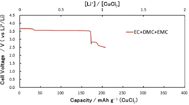
In a very recent trial, CuCl2/C nanocomposite with mesoporous carbon was used to immobilize the active CuCl2 phase into mesopores in a 1 M LiPF6 in EC, dimethyl carbonate (DMC), and ethylene methyl carbonate (EMC) (1:1:1 by vol.) electrolyte.
However, no clear effects of using mesoporous carbon were seen, as the theoretical potential of the electrochemical reactions was not definitely reached and the discharge capacity was as low as half of the theoretical capacity.78
- 15 -
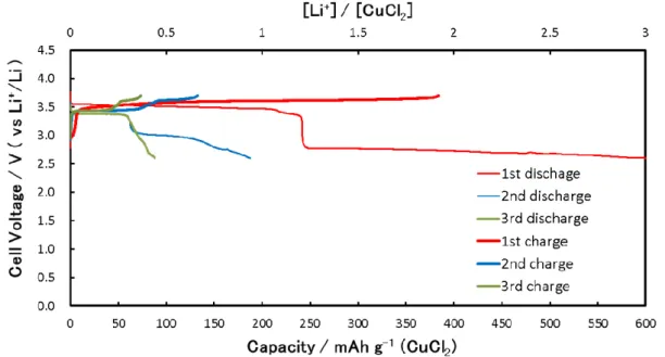
Investigation of another potential transition-metal chloride-based battery system—a cobalt chloride (CoCl2) prepared through application of the casting film process and vacuum-drying in 1 M LiPF6 in EC, DMC, and EMC (1:1:1 by vol.) electrolyte—produced results similar to those in previous research, with no clear two-stage plateaus, initial discharge capacities as large as 850 mAh g−1, and stable cycling performance of 400 mAh g−1 following the second cycle.79
Studies have also been carried out to measure the cycling characteristics of Li/CuCl2
batteries with inorganic electrolyte (LiAlCl4・3SO2) solutions.80 As such systems generate SO2, they are difficult to handle openly and, although approximately 270 cycles were attained in these studies, only about half (200 mAh g−1) of the theoretical capacity of CuCl2 was achieved and the two-electron energy density of the CuCl2
system was not obtained. Recently, the performance of NiCl2 as a cathode electrode has been reported. According to it, it is reported that the performance of 360 mAh g-1 was achieved at 500 ℃ of operation temperature.81
Table 1-5. Gibbs free energies, potentials (voltages), theoretical capacities, and energy densities of transition-metal chlorides.
Zebra batteries, which use sodium-based inorganic molten salt electrolytes and transition-metal chloride cathode materials, are well known for their reversibility and high-temperature (270°C–350°C) operating characteristics. Such batteries primarily use NiCl2 and sodium metal (Na) in the cathode and anode, respectively, and operate via the following electrochemical reactions:82
Cathode : NiCl2 + 2Na++e− ⇄ 2NaCl+Ni [1-8]
Anode : 2Na ⇄ 2Na+ + 2e− [1-9]
Total reaction : NiCl2 + 2Na ⇄ 2NaCl + Ni (2.64 V vs. Na+/Na) [1-10]
MaXb a b n ⊿fG
(kJ mol-1)
Voltage (V)
Capacity (mAh g-1)
Energy Density (Wh g-1)
CuCl2 1 2 1 −175.7 3.08 617 1899
NiCl2 1 2 1 −259.1 2.65 521 1378
CoCl2 1 2 1 −269.8 2.59 504 1306
FeCl2 1 2 1 −302.3 2.42 756 1831
MnCl2 1 2 1 −440.5 1.71 756 1290
LiCl - - - −384.4 - - -
- 16 -
The theoretically calculated operating cell voltage of this set of reactions is 2.58 V (vs Na+/Na) and the theoretical energy density is 414 mAh g−1, which is approximately equal to that of CuCl2. Electrochemically, zebra batteries perform adequately at high temperatures but are most noted for their control of the poor conductive NiCl2 layers on the surfaces of Ni particles and for their reduced operating temperatures and ease of handling.
NaAlCl4 catholyte and other lower melting point alkali metal salts such as NaBr, LiCl, and LiBr have been partially replaced 83,84,85,86 , and Ni/NiCl287, Na/FeCl288 and Na/CuCl289,90-type zebra batteries have been investigated. Although Na/FeCl2 zebra batteries have lower costs and Na/CuCl2 batteries can achieve lower operating temperatures, both require further improvement in terms of cycling performance.
- 17 -
1.4 Copper (II) Chloride-based Lithium Ion Batteries and Their Features
As discussed in the preceding sections, the transition-metal chlorides have disadvantages in terms of self-discharge as a result of their excessive solubility in most organic solvents. It is therefore extremely important to find measures that will block the dissolving of transition-metal chlorides in electrolyte.1.4.1 Solubility of Copper (II) Chloride in Organic Solvent
The solubility characteristics of copper are believed to arise in its electron configuration. For instance, copper (II) and chloride ions bond ionically to create soluble cupric chloride (CuCl2), while copper (I) and chloride ions bond covalently to produce insoluble cuprous chloride (CuCl). Although the suppression of self-discharge by the dissolution of CuCl2 is a very important effect, understanding the behavior of copper (Cu) ions in both aqueous and non-aqueous solvents requires an assessment of the its disproportionation reactions, which are analogous to the electrochemical reactions occurring in batteries.
The Gibbs free energies of Cu and Cu ions are as given as follows:12
⊿G0f(Cu) = 0 kJ mol−1
⊿G0f(Cu+) = +49.98 kJ mol−1
⊿G0f(Cu2+) = +65.49 kJ mol−1
The potentials of the oxidation and reduction of copper and copper ions are calculated as follows:
Cu+ + e− ⇄ Cu [1-11]
E10 = −(⊿G0f(Cu) − ⊿G0f(Cu+))/(1 ×F) = 0.52 V (NHE)
Cu2+ + e− ⇄ Cu+ [1-12]
E20 = −(⊿G0f(Cu+) − ⊿G0f(Cu2+))/(1 × F) = 0.16 V (NHE)
Cu2+ + 2e− ⇄ Cu [1-13]
E30 = −(⊿G0f(Cu) − ⊿G0f(Cu2+))/(2 × F) = 0.34 V (NHE) F:Faraday constant (96,485 C/mol = 26.8 Ah mol−1)
- 18 -
These formulations correspond to the Latimer diagram shown in Figure 1-4.
+0.52 V cuprous +0.16 V cupric Cu Cu+ Cu2+
+0.34 V
Figure 1-4. Latimer diagram of Cu, Cu+, Cu2+ .
When Cu, Cu+, Cu2+ are mixed in a solvent, the electric potential of E1 falls (moves toward the reduction side) while the electric potential of E2 rises (moves toward the oxidation side), resulting finally in E1 = E2 in the equilibrium state.
The equilibrium constant for Cu, KCu, is then expressed as follows:
2Cu+ ⇄ Cu2+ + Cu [1-14]
KCu=[Cu2+][Cu]/[Cu+]2
Then, from the Nernst equations corresponding to [1-11], [1-12]:
E1 = E10 + RT/F ln ([Cu+]/[Cu]) [1-15]
E2 = E20 + RT/F ln ([Cu2+]/[Cu+]) [1-16]
R:Gas constant (8.314J mol−1 K−1) T:Absolute temperature (K)
Accordingly, because E1 = E2 in the equilibrium state:
E10 - E20 = RT/F ln ([Cu2+][Cu]/[Cu+]2) = 0.05914 log KCu (0.52−0.16) = 0.05914 log KCu
KCu = 106.1 > 0 [1-17]
Because the equilibrium constant has a very large value, reaction [1-14] is promoted, resulting in a state in which most of the ions in the solvent are Cu2+ ions; this is particularly true in aqueous solvents.
When chloride (Cl−) ions are present in the solvent, the equilibrium equation takes the following form:
Cu2+ + Cu + 4Cl− ⇄ 2CuCl2− , [1-18]
- 19 -
for which the Gibbs free energies of Cu and Cu ions are as follows:12, 91
⊿G0f(Cu) = 0 kJ mol−1
⊿G0f(Cl−) = −131.23 kJ mol−1
⊿G0f(CuCl2−) = −240.5 kJ mol−1
⊿G0f(Cu2+) = +65.49 kJ mol−1
The potentials of the oxidation and reduction of copper and copper ions in this case are calculated as follows:
CuCl2− + e− ⇄ Cu + 2Cl− [1-19]
E10 = −(2⊿G0f(Cl−) − ⊿G0f(CuCl2−))/(1 × F) = 0.21 V (NHE)
Cu2+ + 2Cl−+e− ⇄ CuCl2− [1-20]
E20 = −(⊿G0f(CuCl2−) − 2⊿G0f(Cl−))/(1 × F) = 0.47 V (NHE)
Cu2+ + 2e− ⇄ Cu [1-21]
E30 = −(⊿G0f(Cu) − ⊿G0f(Cu2+))/(2 × F) = 0.34 V (NHE), F:Faraday constant (96,485 C/mol = 26.8 Ah mol−1)
which correspond to the Latimer diagram in Figure 1-5.
+0.21 V cuprous +0.47 V cupric Cu CuCl2− Cu2+
+0.34 V
Figure 1-5. Latimer diagram of Cu, CuCl2−, Cu2+ .
It is possible for Cu+ to exist stably in a solvent with Cu, Cu+, Cu2+, and Cl−. In this case, the equilibrium constant, KCu’, is given as
KCu’ = [Cu2+][C l−]4/[CuCl2−]2,
and the Nernst equations for [1-19], [1-20] are then given by
E1 = E10 + RT/F ln ([CuCl2−]/[Cu][Cl−]2) E2 = E20+RT/F ln ([Cu2+][Cl−]2/[CuCl2−])
- 20 -
The equilibrium state, E1 = E2, is then given as
E10-E20 = RT/F ln ([Cu2+][C l−]4/[CuCl2−]2) = 0.05914 log KCu’ (0.208−0.466) = 0.05914 log KCu’
KCu’ = 10−4.36 ≒ 0
The very small value of the solution confirms that Cu+ (CuCl2−) can exist stably in this solvent.92
Although the above analysis focused on aqueous solution-based solutions, it is useful to consider the electrochemical reactions driving the behavior of Cl−, Cu, Cu+ (CuCl2−), and Cu2+ as well as Li+ in non-aqueous solvent-based conditions. Because the stable presence of Cu+ (CuCl2−) and/or Cu2+ in the solvent depends on the presence of Cl−, the effects of Cl− concentration on Cu, Cu+ (CuCl2−), and Cu2+ have been studied thoroughly in the contexts of copper corrosion fields and electrolysis.
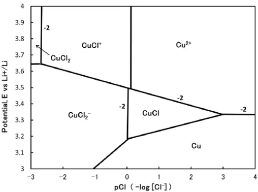
Figure 1-6 show a potential-pCl diagram, which is constructed based on the thermodynamic data in Table 1-6, for copper in an aqueous solvent at pH = 1 and 25°C. It is seen from the figure that, in the absence of or at low concentrations of Cl−, Cu2+ (and not CuCl2) is the most stable form of copper in the solvent. However, as the Cl−concentration increases, Cu+ becomes the most stable solute and the copper complexion of the solution deepens. Similar results for copper electrolysis were reported by K. Murase et al..93 This potential-pCl copper diagram suggests that an insufficient concentration of Cl− in the solvent will severely curtail the formation of CuCl2, resulting in the dissolution of Cu2+ into the solvent. Accordingly, the extent to which Cu2+ occupies the CuCl2 formation and suppresses its solubility has been an important subject of reseatch.94,95,96,97,98
Table 1-6. Thermodynamic data used to construct the potential-pCl diagram in Figure 1-6.94, 95, 98
Cu2+ + 2e- ⇄ Cu E = 0.337 + 0.0295 log [Cu8 2+]
Cu2+ + Cl- + e- ⇄ CuCl E = 0.55 + 0.059 log [Cu2+] + 0.059 log [Cl-] CuCl + e- ⇄ Cu + Cl- E = 0.14 - 0.059 log [Cl-]
CuCl2 + e- ⇄ CuCl2- E = 0.47 – 0.059 log [CuCl2-] Cu+ + e- ⇄ Cu E = 0.520 + 0.059 log [Cu+]
CuCl+ ⇄ Cu2+ + Cl- log [Cu2+] + log [Cl-] – log [CuCl+] = -0.1 CuCl2 ⇄ CuCl+ + Cl- log [CuCl+] + log [Cl-] = 0.7
CuCl + Cl- ⇄ CuCl2- log [CuCl2-] – log [Cl-] = -2 CuCl ⇄ Cu+ + Cl- log [Cu+] + log [Cl-] = -6.7