Doctor Thesis
Shibaura Institute of Technology
Design and Evaluation of AIRGAIT Exoskeleton's Leg
Orthosis:
Development of a Control Scheme and Strategy for a
Noble Control of Antagonistic Mono- and Bi-Articular
Actuators
Date 2014/September
Graduate School of Engineering and Science
2014 September
Doctoral Dissertation
Design and Evaluation of AIRGAIT Exoskeleton's Leg
Orthosis: Development of a Control Scheme and
Strategy for a Noble Control of Antagonistic Mono- and
Bi-Articular Actuators
Name Mohd Azuwan Mat Dzahir
Student ID NB11503
Major Functional Control System
Department
Graduate School of Engineering and
Science
TABLE OF CONTENTS
CHAPTER TITLE PAGE
TABLE OF CONTENTS i
LIST OF FIGURES v
LIST OF TABLES xi
LIST OF PUBLICATIONS xiii
ABSTRACT xv ACKNOWLEDGEMENTS xvii 1 INTRODUCTION 1 1.1 Problem Statement 2 1.2 Objectives 3 1.3 New Findings/Knowledge 3 1.4 Significance of Research 4 1.5 State of Art 5
1.6 Scopes and Limitations 6
1.7 Outline of the Thesis 6
2 LITERATURE REVIEW 9
2.1 Existed Lower Limb Gait Rehabilitation Orthosis and Evaluations
11 2.2 Motorized Lower-Limb Rehabilitation Orthosis System 11 2.3 Pneumatic Muscle Actuators Attributes 16 2.4 Pneumatic Muscle Actuated Lower-Limb Rehabilitation
Orthosis System
2.6 Pneumatic Muscle Actuators Control System 31 2.7 Co-Contraction of Antagonistic Muscle Control 33 2.8 Simulation of Co-Contraction Model for Antagonistic
Muscles
35 2.9 Co-Contraction Model for Antagonistic Actuators 39
3 SYSTEM DESIGN 41
3.1 Mechanical Structure of Leg Orthosis 43 3.2 Mono- and Bi-Articular Muscle Actuators 43
3.3 PMA Settings 44
3.4 PMA Measurement Setup 45
3.5 AIRGAIT's Prototype 47
3.6 Mechanical System 47
3.7 Safety Features 48
4 MATERIALS AND METHODS 49
4.1 Control Model 49
4.2 Muscle Activation Levels 51
4.3 PID Gains 53
4.4 Procedures 53
4.5 Experimental Tests 57
4.6 Flow of the Research 60
5 CONTROL SYSTEM DEVELOPMENT 63
5.1 Drivers 64
5.2 xPC Target 65
5.3 xPC Target Configuration 65
5.4 Simulink Simulation 66
5.5 Feedback Control Model 67
5.5.1 Controller Algorithm 67
5.5.2 Kinematic Analysis (Simulated Co-Contraction Model) 72 5.5.3 Derived Co-Contraction Model 78
5.5.5 Simulation of Co-Contraction Model Control Scheme 89 5.5.6 Hysteresis Characteristic of Pneumatic Muscle Actuator 92
5.5.7 PMA Model 95
5.6 Couple Control Model (Computed Torque Method) 98
5.6.1 Introduction 98
5.6.2 Overview of the AIRGAIT Exoskeleton's Leg Orthosis New System
98 5.6.3 Pneumatic Muscle Characterization 99 5.6.4 Control Model and Application to the Orthosis 101 5.6.4.1 Fitting Model of the Non-Linear Behaviour PMA 101 5.6.4.2 Newton Euler's Equation Model 103 5.6.4.3 Geometric Description Model 105
5.6.4.4 Control Model 107
6 RESULTS AND DISCUSSION 111
6.1 Control of the Leg Orthosis WO/S and W/S: Pressure and Position-Pressure Control based on Conventional PID Controller
111
6.2 Control of the Leg Orthosis WO/S: Evaluation on Mono- and Bi-Articular Actuators Position Settings using Simulated Co-Contraction Model Control Scheme
116
6.3 Control of the Leg Orthosis WO/S: Evaluation on the Simulated and Derived Co-Contraction Model Control Scheme
120 6.4 Control of the Leg orthosis WO/S: Evaluation on
Antagonistic Mono- and Bi-articular Actuators using Co-Contraction Model Control Scheme
122
6.5 Control of the Leg Orthosis W/S: Attributes in Implementing Antagonistic Mono-Articular with an Addition of Bi-Articular Actuators
127
6.6 Control of the Leg Orthosis WO/S: Evaluation on the Designed Controllers using Derived Co-Contraction Model Control Scheme
130
Designed Controllers using Derived Co-Contraction Model Control Scheme
6.8 Control of the Leg Orthosis WO/S: Evaluation on the Antagonistic Bi-Articular Actuators Reliability Without the Presence of Knee Joint’s Antagonistic Mono-Articular Actuators
145
6.9 Control of the Leg Orthosis WO/S: Evaluation on the Internal Pressure and Resultant Torque Generated from the Antagonistic Actuators
150
6.10 Control of the Leg Orthosis WO/S: Evaluation between the Conventional PID and Co-Contraction Model Control Scheme’s Controllers
154
6.11 Human Muscle Activation Based on Electromyography (EMG) signals
158 6.12 Couple Control Model: Sine Signal and Real Trajectory
Tests
163
7 CONCLUSIONS AND RECOMMENDATIONS 169
REFERENCES 173
LIST OF FIGURES
FIGURE NO. TITLE PAGE
1 (a) LOKOMAT; (b) LokoHelp; and (c) ReoAmbulator 13 2 (a) LOPES; (b) ALEX; and (c) NEUROBike 14 3 (a) robotic gait rehabilitation (RGR) trainer; and (b)
LOKOIRAN
16 4 (a) hip orthosis; (b) robotic gait trainer (RGT); and (c)
ankle-foot orthosis (AFO)
19 5 (a) powered lower-limb orthosis; (b) RGTW; and (c)
powered ankle-foot exoskeleton
20 6 (a) KAFO; CPM; and power-assist lower-limb orthosis 22 7 (a) AAFO; (b) bio-inspired active soft orthotic for ankle-foot
pathologies; and (c) active modular elastomer for soft wearable assistance robots
24
8 (a) inexpensive KAFO; (b) orthosis for walking assistant; and (c) 6 DOF robotic orthosis for rehabilitation
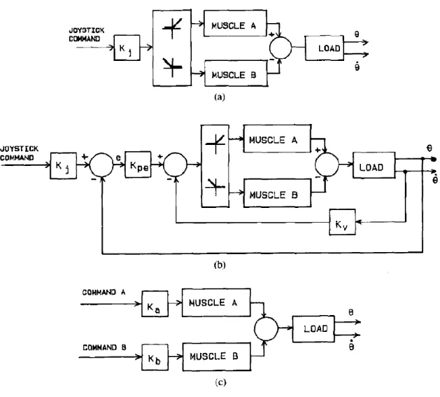
25 9 (a) is open loop reciprocal control; (b) is P-D closed loop
reciprocal control; and (c) open loop co-contraction control [97]
36
10 Schematic diagrams for body weight support gait training system (AIRGAIT)
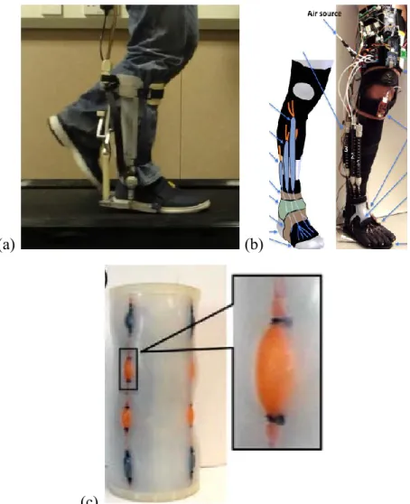
42 11 PMA positions for leg orthosis; (a) antagonistic
mono-articular actuators for hip and knee joints; and (b) bi-mono-articular actuators
44
and (b) PMA setting 2
13 Experiment setup for measuring the McKibben muscle actuator’s characteristics
46 14 Body weight support gait training system (AIRGAIT)
prototype
47 15 Control of leg orthosis without a subject (WO/S) 58 16 Control of leg orthosis with a subject (W/S) 59
17 Embedded control system 64
18 xPC Target system for AIRGAIT exoskeleton 66 19 Schematic diagram of the exoskeleton of the AIRGAIT leg
orthosis controller schemes using MATLAB simulation of co-contraction model based P controller
69
20 Schematic diagram of the exoskeleton of the AIRGAIT leg orthosis controller scheme; co-contraction model based P controller
70
21 Schematic diagram of the exoskeleton of the AIRGAIT leg orthosis controller scheme; co-contraction model based PP controller
71
22 Co-contraction model using MATLAB simulations for antagonistic mono-articular actuators at hip joint
74 23 Co-contraction model using MATLAB simulations for
antagonistic mono-articular actuators at knee joint
75 24 Co-contraction model using MATLAB simulations for
antagonistic bi-articular actuators based on hip joint
76 25 Co-contraction model using MATLAB simulations for
antagonistic bi-articular actuators based on knee joint
77 26 AIRGAIT Exoskeleton leg orthosis design kinematics for the
antagonistic mono- and bi-articular actuators
79 27 Antagonistic mono-articular actuator contraction patterns for
the hip joint
83 28 Antagonistic mono-articular actuator contraction patterns for
the knee joint
(positional based data)
30 Two link leg manipulators model 87 31 Control paradigm's schematic diagram for the system using
PSO optimization method
90 32 Control system simulation outputs 91 33 Hysteresis model for time cycle of 5 seconds tested without a
load
93 34 Hysteresis model for time cycle of 10 seconds tested without
a load
93 35 Hysteresis model for time cycle of 20 seconds tested without
a load
94 36 Hysteresis model for time cycle of 20 seconds tested with
0N, 100N, 200N, and 300N loads
94 37 Co-contraction model control scheme's strategy 96 38 Controlled values of the muscle activation levels for the
antagonistic mono- and bi-articular actuators
97 39 AIRGAIT exoskeleton's leg orthosis antagonistic actuators 99 40 Static characterization of pneumatic muscle 100 41 Graphical visualization of the fitting polynomial equation 102 42 Schematic representations of the AIRGAIT exoskeleton's leg
orthosis two-link model
104 43 Schematic representations of the mono-articular actuators 106 44 Schematic representations of the bi-articular actuators 106 45 Block diagram of the couple control model 110 46 (a) Pressure control using conventional PID controller; and
(b) position-pressure control using conventional PID controller
112
47 Joint excursions for; (a) pressure control; and (b) position-pressure control using conventional PID controller tested WO/S
113
48 Hip and knee joint excursions for pressure control using conventional PID controller tested W/S
using conventional PID controller tested WO/S and W/S 50 Hip joint excursions for co-contraction model controller
scheme based P controller using MATLAB simulation
118 51 Knee joint excursions for co-contraction model controller
scheme based P controller using MATLAB simulation
119 52 Hip and knee joint excursions for co-contraction model
controller scheme based on; (a) simulated, and (b) derived co-contraction model control scheme
121
53 Hip joint trajectories for the control of the leg orthosis WO/S using a co-contraction model control scheme
124 54 Knee joint trajectories for the control of the leg orthosis
WO/S using a co-contraction model control scheme
125 55 Hip and knee joint trajectories at different GC speeds of 5s,
4s, and 3s for the tests with W/S using mono-articular alone and with addition of bi-articular actuators
128
56 Hip and knee joint trajectories at different GC speeds of 2s, and 1s for the tests with W/S using mono-articular alone and with addition of bi-articular actuators
129
57 Joint trajectories of the leg orthosis controls between two designed control schemes tested WO/S; (a) P controller, and (b) PP controller
133
58 End point trajectories for the leg orthosis WO/S using co-contraction model based P and PP controllers
136 59 Gait velocity of the hip joint for the Position (P) control tests
WOS at different GC speeds of 4, 3, 2, and 1 second
137 60 Gait velocity of the knee joint for the Position (P) control
tests WOS at different GC speeds of 4, 3, 2, and 1 second
138 61 Gait velocity of the hip joint for the Position-Pressure (PP)
control tests WOS at different GC speeds of 4, 3, 2, and 1 second
139
62 Gait velocity of the knee joint for the Position-Pressure (PP) control tests WOS at different GC speeds of 4, 3, 2, and 1 second
63 End point trajectories for the leg orthosis W/S using co-contraction model based P and PP controllers
141 64 Effective work and inertia for the control of leg orthosis for
both WO/S and W/S tests using co-contraction model based P and PP controllers
144
65 Leg orthosis with L-shaped bar at knee joint 146 66 Hip and knee joints trajectories for leg orthosis controls
tested WO/S using developed PP controller based co-contraction model control scheme
147
67 End point trajectories for the previous and improved design leg orthosis WO/S using PP controller scheme based co-contraction model
149
68 Internal pressures for antagonistic mono-articular actuators (hip joint) at different GC speeds
151 69 Internal pressures for the antagonistic mono-articular
actuators (hip joint) at different GC speeds
152 70 Resultant torques generated for the antagonistic mono- and
bi-articular actuators at different GC speeds
153
71 Simple schematic diagrams for pressure and position-pressure controls using conventional PID and co-contraction model
155
72 Hip joint excursions for all evaluated control schemes 156 73 Knee joint excursions for all evaluated control schemes 156 74 EMG signals of the normal walking on the treadmill 160 75 EMG signals of the normal walking on the treadmill with
attached orthosis
161 76 EMG signals of the normal walking on the treadmill with
assisted orthosis
162 77 Sine trajectories test without a subject (WO/S) for different
frequencies (a) 0.05 Hz, and (b) 0.1 Hz. The red dashed line is the input signal and the blue continuous line is the measured angles assumed by the orthosis
164
frequencies (a) 0.5 Hz, and (b) 1.0 Hz. The red dashed line is the input signal and the blue continuous line is the measured angles assumed by the orthosis
79 Sine trajectories test with a subject (W/S) for different frequencies (a) 0.5 Hz, and (b) 1.0 Hz. The red dashed line is the input signal and the blue continuous line is the measured angles assumed by the orthosis
166
80 Squared trajectory tests with a frequency of 0.5 Hz. The red dashed line is the input signal and the blue continuous line is the measured angles assumed by the orthosis
167
81 Real trajectories for the hip and knee angles for a random walk. The red dashed line is the input signal and the blue continuous line is the measured angles assumed by the orthosis
167
82 Ankle position paths for a random walk. The red dashed line is the input signal and the blue continuous line is the real position assumed by the orthosis
LIST OF TABLES
TABLE NO. TITLE PAGE
1 Comparison of existing pneumatic muscle actuated lower-limb rehabilitation orthosis systems
28 2 Trajectory data of the co-contraction model 52 3 PID parameters and muscle activation levels of the previous
system using Heuristic method
54 4 PID parameters and muscle activation levels of the new
system using Heuristic method
54 5 PID parameters and muscle activation levels of the new
system using Ziegler-Nichols method
55 6 Existed lower limb gait rehabilitation orthosis system
comparison
56 7 Models verification using the LS and RLS prediction
methods
86 8 Particle swarm optimization (PSO) control parameters 86 9 Sensibility analysis of the fitting curve of the exponential
data as a function of the degrees of the polynomial surface
103 10 Numeric values of the parameters of the fitting polynomial
equation
103 11 Numerical data of the orthosis geometry 105 12 Pearson coefficient of determination (r2) for mono-articular
actuators alone and with addition of bi-articular actuators
126 13 Pearson coefficient of determination (r2) for co-contraction
model based P and PP controllers
14 Pearson coefficient of determination (r2) values for the improved leg orthosis at hip and knee joints
148 15 Correlation coefficient (CC) and Pearson coefficient of
determination (r2) values for all evaluated control schemes
LIST OF PUBLICATIONS
PAPER NO. TITLE PAGE
1 Recent Trend in Lower-Limb Robotic Rehabilitation Orthosis: Control Scheme and Strategy for Pneumatic Muscle Actuated Gait Trainers
-
2 Design and Evaluation of the AIRGAIT Exoskeleton: Leg Orthosis Control for Assistive Gait Rehabilitation
- 3 Development of Gait Training System Powered by
Antagonistic Mono-and Bi-Articular Actuators Using Contraction Model Control Scheme
-
4 Computed-Torque Method for the Control of a 2 DOF Orthosis Actuated Through Pneumatic Artificial Muscles: A Specific Case for the Rehabilitation of the Lower Limb
-
5 Antagonistic Mono- and Bi-Articular Pneumatic Muscle Actuator Control for Gait Training System using Contraction Model
-
6 Development of Body Weight Support Gait Training System using Pneumatic McKibben Actuators: Control of Lower Extremity Orthosis
-
7 Recent Trend in Lower-Limb Robotic Rehabilitation Orthosis: Pneumatic Muscle Actuated Gait Trainer Systems
- 8 Control of Lower Limb Orthosis: Simple Paradigm for the
Control of antagonistic actuators
- 9 Antagonistic mono- and Bi-Articular Actuators Contraction
Model for Body Weight Support Gait Training System
10 Trends and Issues in Neuro-Rehabilitation Robotics - 11 Bi-Articular Muscle Actuators Kinematics Analysis for Gait
Training System
- 12 Development of Body Weight Support Gait Training
System using Pneumatic McKibben Actuator: Development of Measurement and Control System
ABSTRACT
operates to its full capacity. The evaluation was based on the gait cycle (GC), trajectory of the hip and knee joints, maximum angle extension of the joints, foot trajectory, effective work, inertia, gravitational effect, and time shift. The results revealed that the proposed co-contraction model control scheme and strategy were able to co-contractively actuate the mono- and bi-articular actuators simultaneously as well as increase stiffness and stability at both hip and knee joints.
ACKNOWLEDGMENTS
In preparation of this thesis, various parties have contributed directly or indirectly in many ways during the execution of the project. First and foremost, I wish to express my sincere appreciation to my doctoral project supervisor, Prof. Shin-Ichiroh Yamamoto for his continuous guidance, encouragement and advice. Without his constant support and assistance, this project would not have been the same as presented here. The sharing of his invaluable knowledge and constructive ideas was the key way to success in this project.
Special thanks to my wife for her untiring efforts and practical suggestions which had been contributed significantly toward the success of this project were greatly appreciated.
Last but not least, I would also like to extend my gratefulness to my fellow course mates, friends and seniors for their help and assistance on various matters. Their support was indeed very valuable for me. Thank you.
CHAPTER 1
INTRODUCTION
joints (i.e., flexion, extension, abduction, adduction, dorsiflexion, plantar-flexion, inversion, eversion, etc). However, the implementation of bi-articular muscle actuators either to compensate the lack of force/torque at the joints or to improve the control scheme and strategy of the lower-limb rehabilitation orthosis have yet to be extensively investigated and made commercially available.
For understanding the coordination of muscles in complex movements, it is of particular interest to know the potential actions of all types of muscles involved. At the present the action of muscles that pass over more than one joint is mainly described with respect to movements in the joints that are crossed. However, Elfman et al., in 1939-1940 hypothesized that bi-articular muscles might play a role in saving energy expenditure. Bi-articular muscles is the muscles that cross two joints rather than just one joint such as 'hamstring' and 'rectus femoris' which cross both hip and knee joint. The function of these muscles is complex and often depends upon their anatomy and the activity of their other muscles at the joints. Bi-articular muscles can play a unique role in the transformation of rotation in the knee joint into the translation of the body centre of gravity in such a way that this centre of gravity is continuously accelerate during push-off, thus these results made it a likely assumption for understanding the co-ordination of muscles in complex movements. The literature of this thesis will reviews all the current lower-limb rehabilitation orthosis systems then make a comparison in terms of its evaluation, design, as well as its control scheme and strategy, with the aim to clarify the current and ongoing research in this lower-limb robotic rehabilitation field.
1.1 Problem Statements
rehabilitation field is yet to be extensively investigated and made commercially available. This then provides the motivation and purpose to investigate a noble control for the antagonistic bi-articular actuators using a suitable model paradigm. In addition, even though lots of researches had been investigated regarding the co-contraction movements of human antagonistic muscles. However, their model implementation in controlling the antagonistic muscle actuators of lower-limb orthosis is not extensively discovered. This research thesis focuses on the implementation of the antagonistic mono- and bi-articular actuators using pneumatic muscles to drive the lower-limb orthosis. Thus, simply actuating the actuators might not give a good result on the joint’s stiffness and stability of the lower-limb leg orthosis and its position trajectory. Therefore, the simultaneous co-contraction movements between the agonist and antagonist muscle actuators should also be considered during the control system scheme and strategy.
1.2 Objectives
This research thesis embarks on the following objectives:
i. To optimize the body weight support gait training system (AIRGAIT) by implementing antagonistic mono- and bi-articular actuators using pneumatic artificial muscles.
ii. To derive and design a model control scheme and strategy for the AIRGAIT exoskeleton's leg orthosis system.
iii. To develop and evaluate the controllers for the AIRGAIT exoskeleton’s leg orthosis using real time control system.
1.3 New Findings/Knowledge
This research will result in new potential towards application of lower-limb pneumatic muscles actuated rehabilitation orthosis system. Some of the concepts and novel knowledge acquired from this research will lead to a new exploration as follows:
and bi-articular actuators using pneumatic muscles similar to human musculoskeletal system as an alternative for human compliance rehabilitation robotics system.
ii. Derivation of the model paradigm for estimating the co-contraction patterns of the antagonistic mono-and bi-articular actuators based on angular positional data.
iii. Derivation of the control strategy that able to reduce the nonlinearity effects of the pneumatic muscles using simple approach.
iv. The therapists’ perception in using the body weight support gait training system of AIRGAIT exoskeleton as alternative for clinical rehabilitation training can be evaluated.
1.4 Significance of Research
People suffering from walking deficiencies have better recovery expectancies if they undergo intensive rehabilitation programs. However, standard rehabilitation programs necessitate intensive efforts of one, two, or even three physiotherapists to move the patient, this being potentially painful for the therapists as well. Rehabilitation robotics is a promising research avenue to take over some of this time- and energy-consuming workload. There is argument that robots should be developed to assist with therapeutic activities that are difficult or impossible for the therapist to administer alone. For instance, attempting overground gait and balance training in a patient with both heavy weight and low function is difficult and unsafe for the average therapist. Therefore, the goal is not to replace the physiotherapist, but to relieve him of the most painful aspects of his task, eventually leading to longer and/or more frequent training sessions. The goals of such devices are to assist the therapist so that they may safely train patients in standing, walking, and performing balance activities early after injuries. These tasks are difficult for therapists; however, with robotic technologies, they are possible.
Rehabilitation robots need to be adjustable and programmable, because the robot can be used for multi reasons. Meanwhile, an industrial robot is always the same; there is no need to change the robot unless the product it is working with is bigger or smaller. This development is capable of solving the problem of the lack of the doctors, enhances the efficacy of clinician's therapies; and increasing the ease of activities in the daily lives of patients. The operations can be conducted remotely, creating medical teamwork while in different places and relieve the psychological stress of doctors. For the developing country or places that not have enough medical structure, remote-control system giving hope for them to have better medication treatment. In addition, this could also be served as a reinforcement of emergency medical care.
In parallel, developing autonomous rehabilitation robots might also be useful to extend the therapy at home. If patients could begin therapy sessions quickly, this would translate into more time for repetitions and activities and thus, greater functional outcomes. Unfortunately, easy-to-use does not necessarily translate into low cost. In fact, sometimes being able to deliver an easy-to-use and highly flexible systems were results in substantial costs. In the end, for devices to gain widespread acceptance in small rehabilitation clinics, the costs for providing and using these systems must first come down.
This research will result in a highly compliance body weight support gait training system for lower-limb disability of stroke and SCI patients. The AIRGAIT system allows the gait motion training with different body weight support (BWS) on a treadmill. Furthermore, it also allows patients to train their disabled legs for a repetitive gait motion training at different gait cycle (GC) speed. The measurement system which identifies the subject’s center of mass (CoM) and center of pressure (CoP) was also developed together with the AIRGAIT system. This allows the therapists to analyze the condition of the subject and identify the level of training to be practice. Finally, it is also expect that some design methodologies developed for rehabilitation robotics might also be adapted to active prosthesis design.
1.5 State of Art
state-of-the-art of lower-limb exoskeleton robots that are applied in the areas of rehabilitation and assistive robotics. In general, the development of rehabilitation robotics application is motivated by the promise that people with severe impairments will benefit from these developments. Although, over the decades, there has been continuous progress in technological developments, only few systems have become commercially available, and even fewer were accepted for provision. Based on the literature review, the lower-limb rehabilitation orthosis which implemented antagonistic mono- and bi-articular actuators using pneumatic muscle has yet to be extensively investigated and commercially available. However, the development of this technology itself is obviously an essential element of progress in the domain of rehabilitation robotics. In addition, the main requirements of the lower-limb exoskeleton robot are identified and the mechanical designs of existing lower-limb exoskeleton robot are classified. The design difficulties of a lower-limb exoskeleton robot are discussed.
1.6 Scopes and Limitations
i. The model derivation is based on the antagonistic mono-articular (i.e., hip and knee joints) and bi-articular actuators of the AIRGAIT exoskeleton's leg orthosis system.
ii. All the measurements, control system, experimental tests, and design will be based on the developed body weight support gait training system of AIRGAIT exoskeleton.
iii. The simulation program and control paradigm are coded in MATLAB language, while the control system will be modelled using SIMULINK and xPC Target toolbox.
1.7 Outline of the Thesis
content of the research thesis which consists of seven different chapters including introduction, literature review, design system, methodology, control system, results and discussion, and conclusions.
Chapter 1: The first chapter provides a general introduction and background of the whole research including the problem of statement, specific objectives, scopes and limitation, and outline of the thesis.
Chapter 2: The second is the literature review section which provides detailed descriptions on a few topics related to this project. At the beginning of this chapter, an introduction on human motion research is included. General knowledge on stroke, including rehabilitation therapy, mechanical system and laws of robotic, is also discussed with greater detail in this chapter. Finally, some of the existing assistive robotic leg orthosis researches including their descriptions are included.
Chapter 3: The third chapter is the design system and evaluation section for the AIRGAIT exoskeleton's leg orthosis. All of the mechanical structure of leg orthosis, antagonistic mono-articular (i.e., hip and knee joints) and bi-articular actuators, AIRGAIT's prototype, mechanical system, and safety features were described thoroughly in this section.
Chapter 4: The fourth chapter describes about the materials and methods used in the execution of this project. MATLAB, Simulink, and xPC Target toolbox which were used extensively in this project, is briefly discussed as an introduction to this chapter. Subsequently, the procedures and experimental tests for the controller schemes evaluation were discussed in details.
Chapter 6: The sixth chapter consists of the results and discussion of this research project which delves into several sub-topics based on the assessments evaluation, control tests, and analysis. This section describes the evaluation on the antagonistic actuators’ settings, limitation and performance of the antagonistic mono- and bi-articular actuators in manipulating the leg orthosis when tested without a subject (WO/S) and with a subject (W/S). Full BWS was implemented during the test W/S where the load supported by the leg orthosis was at its maximum capacity. This assessment will optimize the control scheme and strategy so that it will operate at its maximum capability. The options for the subject were not really critical as the focus of the research is on the design controller. As such, the subject chosen was young, healthy, and not bearing any neurological disorder.
CHAPTER 2
LITERATURE REVIEW
The outcomes of rehabilitation therapy, which implemented body weight support treadmill training for incomplete spinal cord injuries (SCI) and stroke patients, were reported in several previous studies since the 1990s. SCI involves damage to any component of nerves or spinal cords located at the end of the spinal canal, which is either complete or incomplete. However, it often causes permanent changes in strength, sensation and other body functions below the side of the injury. The symptoms vary widely, beginning with pain to paralysis and then to incontinence. The paralysis could be identified as a weakness which might occur with abnormal tone (e.g., spasticity or rigidity). During the stance phase, leg instability (i.e., hyperextension or knee buckling) may result in unsafe walking, pain and inefficient energy. Moreover, inadequate limb clearance, impaired balance, sensory deficits and pain during the swing phase may contribute to falls, loss of balance and increased nervousness associated with walking. Furthermore, a loss of motor control prevents a patient from performing a precise movement in coordination with timing and intensity of muscle action.
daily upright walking training. Based on the rehabilitation sessions, nearly 80% of patients with incomplete spinal cord injuries (a total of 33 individuals) were capable of walking independently after the treadmill training, with partial body weight support. In addition, the clinical evaluation on complete paraplegic and tetraplegic patients was carried out by Dietz et al., to differentiate the effects of BWS and joint movements on the leg muscle activity pattern during assisted locomotion in SCI patients [3 – 4]. However, this training procedure was physically difficult for therapists to execute for long durations of time. Recently, robot-assisted therapy devices became increasingly used in SCI rehabilitation therapy. This assistive robot either compensates the functionalities that a patient does not have, or tries to recover the impaired functionalities. Even though it may not be able to fully compensate impairments, or even provide a cure, it should be able to enhance or extend certain impaired functions; sequentially, raising the quality of life, encouraging independent living, as well as, supporting the need for social interactions and communications. Depending on the degree and location of the injury, the actual rehabilitation or treatment can vary widely. In many cases, substantial rehabilitation and physical therapy are required for spinal cord injuries, particularly if the patient’s injuries interfere with daily life activities.
In addition, the clinical study on the developed robotic gait training such as LOKOMAT, LokoHelp, ReoAmbulator, and Alex had been evaluated [9, 12, 13, 17, and 18]. The tests were performed on patients suffered with incomplete or/and complete SCI. The results proved that robotic assisted gait training not only able to improve the gait ability of the patients. However, the requirement for therapeutic assistance was also reduced. Additionally, the burden of the physiotherapist in managing time-consuming rehabilitation training also could be solved.
Consequently, the interest in this field has grown exponentially in recent years, mainly due to the demand for a much more compliant and interactive human-robotics system. Therefore, this work will appraise all the current existing lower-limb rehabilitation orthoses, based on compliant actuator systems, in terms of evaluation, design, control scheme and strategy. They will then be compared between one another, with the intent of clarifying current and on-going research in the lower-limb robotic rehabilitation field.
2.1 Existed Lower Limb Gait Rehabilitation Orthosis and Evaluations.
Numerous assistive orthosis systems for gait rehabilitation have been developed, delving into several types of lower-limb rehabilitations, such as: treadmill gait trainers, over-ground gait trainers, stationary gait and ankle trainers, foot-plate-based gait trainers and active foot orthoses for the neurologically impaired (including stroke and Spinal Cord Injury (SCI) patients) [5 - 8]. These systems implemented very unique mechanical structures, designs, actuators, methods, control schemes and rehabilitation strategies; as well as, various procedures to ensure the reliability and robustness of the systems when compared to others. The rapid development of rehabilitation robotics over the last decade is to fully restore or improve the mobility of affected limb functions, and to help patients achieve a better life.
2.2 Motorized Lower-Limb Rehabilitation Orthosis System.
researched in many rehabilitation centres as one of the best examples for gait orthosis that can be used for lower-limb disabilities [9 - 11]. This orthosis system is shown in Figure 1(a). It consists of three main parts: body weight support, treadmill and powered leg orthosis. The Direct Current (DC) motor, with helical gears, was used for the actuation power of the system to precisely control the trajectory of the hip and knee joints. Considerable control algorithms have been implemented into this system to improve its performance, such as position, adaptability, impedance controllers, etc. To stimulate the locomotor function of the spinal cord and activate leg muscles that have lost the capacity to actuate voluntary movement, it is important to provide adequate afferent input to the affected lower-limb. It could be anticipated that the afferent input produced using the automatically based training, is at least as efficient as that generated using the manual training.
Figure 1(b) shows the treadmill gait trainer system which incorporated the electromechanical gait device with the treadmill/gait training, known as the LokoHelp (LokoHelp Group, Germany). The LokoHelp used a different mechanical system compared to the LOKOMAT, which implemented the powered leg orthosis. The foot powered orthosis, known as "Pedago", used an electromechanical gait device that was designed to provide a gait motion during training session [12]. The control device helps to move the patients' foot trajectory with a fixed step length of 400mm, in which the gait cycle (GC) speed can be varied from 0 up to 5 km/h. Based on the research findings, it was proven that walking ability could be improved by incorporating the task oriented gait training with mechanical gait training devices or with treadmill training.
the improvements in balance and gait, which is comparable to conventional/manual physical rehabilitation therapies.
(a) (b)
(c)
Figure 1 (a) LOKOMAT; (b) LokoHelp; and (c) ReoAmbulator
Moreover, it is also possible to imply unhindered walking practice in the orthosis device where the required forces/torques for imposing a gait pattern are determine based on the system's evaluation.
(a) (b)
(c)
Figure 2 (a) LOPES; (b) ALEX; and (c) NEUROBike
placed at the hip and knee joints of the exoskeleton's leg orthosis, by means of a force-field controller.
Later, a stationary gait and ankle trainers system was developed to provide neural-rehabilitative treatments aimed at recovering walking abilities in post-stroke patients. This orthosis system employed the use of brushless servomotors and pulleys to actively control the angular excursions of the gait orthosis, known as the neural-rehabilitative platform for bedridden post-stroke patients (NEUROBike) [19]. The prototype of this system is shown in Figure 2(c). The passive and active exercises were emphasized in this system by implementing the kinematic models of leg-joint angular excursions during both ‘sit-to-stand’ and ‘walking’ into the control algorithms. To summarize, providing a number of exercises at an early phase based on the intensity and the severity of the pathology is required by the programmed therapy. In addition, customized treatment adapted by this system may facilitate patients to increase flexibility in lower limb control, which leads to significant improvements in motor control performance during locomotion.
In addition, the Robotic Gait Rehabilitation (RGR) trainer's prototype was also invented within the same year as the NEUROBike system, to assist treadmill gait retraining for patients with unusual gait patterns that were associated with exaggerated pelvis obliquity, illustrated in Figure 3(a). This orthosis is composed of three subsystems: stationary frame, Human-Robot Interface (HRI) and treadmill training. Servo-tube linear electromagnetic actuators were used to generate the power source for the exoskeleton [20]. Based on a hypothesis, the correction of a stiff-legged gait pattern entails addressing both the primary and secondary gait deviations to restore a physiological gait pattern. Therefore, an expanded impedance control strategy was used to generate the corrective moments, only when the leg is in swing motion, by switching the force field that affects the obliquity of the pelvis. It has been demonstrated that this system can be effective in guiding the pelvis to frontal plane via force fields used for altering pelvic obliquity.
connected to a slide-crank mechanism via belts and pulleys to provide the energy for the system [21]. The implemented control system enables flexibility in motion and permits subjects to change the speed of the foot plates by engaging the speed control mode and the admittance control mode.
(a) (b)
Figure 3 (a) robotic gait rehabilitation (RGR) trainer; and (b) LOKOIRAN The evaluated motorized lower-limb gait rehabilitation orthosis systems mentioned above are only represented a fraction of the currently existing rehabilitation orthoses. However, it could be summarized from these examples that its development has reached an advanced level; whereby, many of the lower-limb gait rehabilitation orthoses, based on electrical motors, have already been commercialized. With its growth speed in the mechanical design, as well as, the implementation of advanced control schemes and strategies, the space available for enhancements might closely reach its peak.
2.3 Pneumatic Muscle Actuators Attributes.
also inhibits nonlinear behaviours such as hysteresis, compressibility and time variance. However, in exchange, this pneumatic muscle also has an inherently compliant attribute which is suitable for a human-robotics system. This type of actuator is similar to the human muscle principle; shorter muscle length produces smaller contracting force and vice versa. Furthermore, it is comparable to electric actuators due to the direct coupling to the load and structural optimization. In addition it also has a high power to weight ratio.
In addition to the abovementioned attributes, there exist two main weaknesses that limit the application of pneumatic muscle. The first weakness is the nonlinear behaviour of pressure build-up, and the second weakness is the hysteresis effect due to its geometric structure. These drawbacks cause complexity when scheming high-performance control systems. Therefore, this research is dedicated to solve these problems, using a simple paradigm and control strategy for handling the sudden increase in pressure and hysteresis behaviour of the PMA. Based on the proposed empirical-based static force mathematical model, which consist of a correction factor caused by the effect of the end caps, it showed an inconsistency of high contracting ratios derived by the famous researcher Tondu et al., [22]. The extreme difficulty in constructing an accurate mathematical model was established by the fact that nearly all of the present models proposed were approximations. This model was later modified through various methods, used by other researches, to further improve the mathematical model [23 - 30].
2.4 Pneumatic Muscle Actuated Lower-Limb Rehabilitation Orthosis System.
The development of the hip orthosis exoskeleton powered by pneumatic artificial muscle (PAM) was invented by Vimieiro et al., at Bioengineering Laboratory in 2004, as shown in Figure 4(a) [31 - 32]. This exoskeleton system was designed and modelled for patients with a motor deficit, a resultant of Poliomyelitis. It consisted of two main parts: the first is polyethylene pelvic brace to provide the stability for the orthosis system, and the second is polyethylene support for the thigh. This orthosis system implemented the position control using the potentiometers for activating the control valves, either to pressurize the PAM or to return it to neutral status. Based on clinical tests, it was proven that the rehabilitation engineering was able to provide equipment and devices for aiding patients to recover their movements or improve their quality of life. A better gait pattern and an improvement of the left step transposition in the toe-off phase were reported by patients.
Later came the Robotic Gait Trainer (RGT) for stroke rehabilitation, which is an ankle rehabilitation device powered by lightweight Springs Over Muscle (SOM), proposed by Kartik et al. It was developed in 2006, as shown in Figure 4(b) [33]. The design was structurally based on a tripod mechanism with one fixed link. This orthosis device was able to provide the dorsiflexion and plantar-flexion, as well as, the inversion and eversion when moving the foot about the ankle joint. It implemented an angular position for the control system and used two types of sensors (i.e., potentiometer and pressure sensor). In this study, Kartik et al. suggested that the range and position of motion (ROM) are necessary for safe dorsiflexion/plantar-flexion and inversion/eversion movements. This was proven by the results from their analysis which demonstrated that the tripod structure was able to generate a ROM that matches the safe anatomical range of the ankle joint during the gait cycle training.
believed that this orthosis design will be useful in learning human walking biomechanics and providing assistance in the neurological injuries of patients during the rehabilitation training.
(a) (b)
(c)
Figure 4 (a) hip orthosis; (b) robotic gait trainer (RGT); and (c) ankle-foot orthosis (AFO)
the development of rehabilitation orthosis systems and improve the rehabilitative procedures for paraplegic patients.
(a) (b)
(c)
Figure 5 (a) powered lower-limb orthosis; (b) RGTW; and (c) powered ankle-foot exoskeleton
In 2009, Malcom et al., developed the powered ankle-foot exoskeleton, which investigated the role of the tibialis anterior (TA) in the walk-to-run condition (WRT), as shown in Figure 5(c) [39 - 42]. The pneumatic muscles were used to provide the dorsiflexion and plantar-flexion torques through the assisting orthosis for incomplete SCI patients during assist and resist conditions. This orthosis device implemented an electromyography (EMG) control with a feed-forward algorithm; whereby a set of rotary encoders and load cells were used to measure the treadmill belt speed, ankle angle, dorsiflexion and plantar-flexion torques. Through the hypothesis from gait transitions and research evaluations, it was demonstrated that the powered exoskeleton had great potential in fundamental gait studies.
After the introduction of AFO by Ferris et al., the development of this system was later continued by Sawicki et al., a few years later. In 2009, the pneumatically powered Knee-Ankle-Foot Orthosis (KAFO) was proposed through the study of human motor adaptation, gait rehabilitation and locomotion energetics; as shown in Figure 6(a) [43]. Compared to the AFO control system, this system implemented a physiological-inspired controller that utilised the patient's muscle information; which is determined using electromyography to measure the timing and amount of the artificial muscle forces. Based on several research findings, it is believed that powered knee-ankle-foot orthoses are promising for basic science and clinical applications; since they had successfully assisted individuals with incomplete SCI during locomotor training, metabolic energy consumption and neural adaptation for neurologically intact human walkers.
Figure 6(c) shows a power-assist lower-limb orthosis, proposed by Yeh et al., in 2010, for assisting the elderly and individuals suffering from sport injuries such as inability to walk or climb stairs using McKibben pneumatic muscles as the actuation system [45]. For achieving a better tracking performance, an inverse control for the feed-forward compensation was constructed using the hysteresis model, which was then combined with the Loop Transfer Recovery (LTR) feedback control. In addition, to ensure smooth switching between different phases during operation, bump-less switching compensators were implemented into the combine control system. Based on the research findings, it was demonstrated that the orthosis was able to effectively accomplish the assistive function of human locomotion during walking and climbing stairs.
(a) (b)
(c)
Figure 6 (a) KAFO; CPM; and power-assist lower-limb orthosis
muscle, a lightweight and discrete orthosis system was achieved. This design enabled the entire actuation system to be placed behind the leg of the orthosis. A feedback control that utilised a fuzzy logic gait phase detection system was implemented with the use of two types of sensory devices: the first is Force Sensitive Resistors (FSRs), located under the insole of the shoe; the second is the rotary encoder for measuring the angular displacement of the ankle joint. However, it is unlikely that suitable methods of supplying air pressure to the device can be found, even though this system exhibits many desirable features. This system may well be beneficial to after-stroke patients, as it allows a more complete rehabilitation of the ankle joint.
In 2011, bio-inspired active soft orthotic device for ankle foot pathology was developed by Park et al. for treating gait pathologies associated with neuromuscular disorders, as shown in Figure 7(b) [47]. By utilizing the advantages of the pneumatic artificial muscle actuators, an inspired biological musculoskeletal system with muscle-tendon-ligament structure had been introduced as the design of the orthosis system. Three types of sensors were used for the control system: the first is strain sensor for measuring ankle joint angle changes; the second is internal measurement unit (IMU) to measure the orientations of the lower leg and the foot; and the third is pressure sensor to identify the foot ground contacts and gait cycle events. The implemented feed-forward and feedback controllers were able to demonstrate a good repeatability of the ankle joint angle control, respectively. Based on the outcomes of the result, this research is believed to be capable of providing rich spaces for the rehabilitation techniques for ankle pathologies in the near future.
preliminary study of this device system, few improvements should still be made within the design structure and control system.
(a) (b)
(c)
Figure 7 (a) AAFO; (b) bio-inspired active soft orthotic for ankle-foot pathologies; and (c) active modular elastomer for soft wearable assistance robots
Figure 8(a) presents a developed inexpensive pneumatically powered assisted knee-ankle-foot orthosis (KAFO), using McKibben actuators, for providing assistance during gait training; proposed by Teng et al., in 2012 [49]. To determine the relationship between the inclination angles of each joint with pneumatic muscle displacement, the equation was expressed by using a trigonometry method; employed into the control system algorithm and strategy. However, this lower-limb orthosis system is still in the early development stage of design improvement, therefore, further evaluation on system performance has yet to be concluded.
recuperate patients’ walking abilities, as illustrated in Figure 8(b) [50]. The pressure control unit was implemented using the developed Dual Pneumatic Control System (DPCS) by manipulating the Pulse-Width Modulation (PWM) signal to control the valve. This orthosis system has yet to reach its completion and require further improvements in its control scheme and strategy when handling the nonlinearity behaviour of the actuator. The assistant force generated by the orthosis system is not adequate enough for driving the intended task.
(a) (b)
(c)
Figure 8 (a) inexpensive KAFO; (b) orthosis for walking assistant; and (c) 6 DOF robotic orthosis for rehabilitation
Boundary-layer-Augmented Sliding Mode Control (BASMC)-based position controller, to afford an interactive robotic gait training system. It was proven that the implementation of the adaptive impedance control scheme was able to provide the gait motion training, which is comparable to the one provided by physical therapists. Additionally, the result findings demonstrated that an increase/decrease in a human’s voluntary participation during the gait training will result in a decrease/increase of robotic assistance.
Table 1 shows the comparison of existing pneumatic muscle actuated lower-limb rehabilitation orthosis systems. Based on the evaluations of these systems for the past 10 years, it can be concluded that researchers’ interests shifted to the implementation of the natural compliant type of actuators (i.e., McKibben muscle, rubbertuators, air muscle, PAM, PMA, etc.). This was proven by the development of different types of assistive gait rehabilitation orthoses system prototypes, including foot orthoses, hip orthoses, knee-foot orthoses, stationary gait and ankle trainers, over-ground gait trainers with orthoses, mobile over-ground gait trainers and treadmill gait trainers [31-52]. In addition, the improvement of the control system implementation, since the year 2004 up until 2013, showed that researchers were gradually trying to improve the control of pneumatic muscle actuated lower-limb orthoses, as illustrated in Table 1. In the beginning, only a simple angular position control was proposed to activate the control valves. Later, it was shifted to the implementation of proportional myoelectric control, intelligent embedded control, inverse control, feedback control (which utilised a fuzzy logic), rigidity control, and subsequently, the adaptive impedance control.
Table 1 Comparison of existing pneumatic muscle actuated lower-limb rehabilitation orthosis systems Comparison for existed pneumatic muscle actuated lower-limb rehabilitation orthosis systems Orthosis system Time
scale
Robotic
system types Actuators Antagonistic actuators Control system References Hip orthosis
exoskeleton
2004 Hip orthoses McKibben
pneumatic muscle
Mono-articular for hip joint (flexion)
Position control using the potentiometers for activating the control valves
[31 - 32]
Robotic gait trainer (RGT)
2006 Foot orthoses Lightweight spring over muscle (SOM)
Mono-articular for ankle joint (dorsiflexion)
Angular position control system
[33] Ankle-foot orthosis
(AFO)
2006 Foot orthoses McKibben
pneumatic muscle
Mono-articular for ankle joint (dorsiflexion and plantar-flexion)
Proportional myoelectric control using a PC-based controller [34 - 36] Powered lower-limb orthosis 2006 Treadmill gait trainers Pneumatic muscle actuators (PMA)
Mono-articular for hip joint (flexion, extension, abduction, and
adduction), knee joint (flexion and extension), and ankle joint
(dorsiflexion and plantar-flexion)
Intelligent embedded control mechanism (a three level PID joint torque control scheme)
Robotic gait trainer in water (RGTW) 2008 Over-ground gait trainers with orthosis McKibben pneumatic muscle
Mono-articular for hip joint (flexion and extension), and knee joint (flexion and extension)
Position control system [38]
Powered ankle-foot exoskeleton
2009 Foot orthoses Pneumatic artificial muscle (PAM)
Mono-articular for ankle joint (dorsiflexion and plantar-flexion)
Electromyography (EMG) control with feed-forward algorithm [39 - 42] Powered knee-ankle-foot orthosis (KAFO) 2009 Knee and foot orthoses McKibben pneumatic muscle
Mono-articular for knee joint (flexion and extension), and ankle joint (dorsiflexion and plantar-flexion) Physiological-inspired controller using electromyography [43] Continuous passive motion (CPM) 2009 Stationary gait and ankle trainers Pneumatic artificial muscle (PAM) _ _ [44] Power-assist lower-limb orthosis 2010 Over-ground gait trainers (mobile) McKibben pneumatic muscle
Mono-articular for knee joint (extension)
Inverse control and loop transfer recovery (LTR) feedback control
[45]
Active ankle-foot orthosis (AAFO)
2011 Foot orthoses McKibben
pneumatic muscle
Mono-articular for ankle joint (plantar-flexion)
Feedback control which utilized a fuzzy logic gait phase detection system
Bio-inspired active soft orthotic device
2011 Foot orthoses Pneumatic artificial muscle (PAM)
Mono-articular for ankle joint (dorsiflexion, inversion, and eversion)
Feed-forward and feedback controllers
[47]
Active modular elastomer sleeve for soft wearable assistance robots 2012 Knee orthoses Miniaturized McKibben pneumatic muscle
Mono-articular for knee joint (flexion and extension)
Through shape and rigidity control [48] Knee-ankle-foot orthosis (KAFO) 2012 Knee and foot orthoses Pneumatic artificial muscle (PAM)
Mono-articular for hip joint (flexion and extension), and knee joint (flexion and extension)
_ [49]
Orthosis for walking assistant
2013 Hip orthoses Straight fiber pneumatic artificial muscle (PMA)
Mono-articular for hip joint (flexion)
Dual pneumatic control system (DPCS) with pulse-width modulation (PWM) signal [50] Six degree of freedom robotic orthosis for gait rehabilitation
2013 Treadmill gait trainers
McKibben
pneumatic muscle
Mono-articular for hip joint (flexion and extension), and knee joint (flexion and extension)
Adaptive impedance control using boundary-layer-augmented sliding mode control (BASMC)
2.5 Control Scheme and Strategy
The need for improved control strategies in handling the antagonistic actuator of pneumatic muscles will determine the progression of growth in lower-limb rehabilitation orthosis systems. Based on previous research, it is possible to utilize a standard PID controller in a feedback loop to control the joint’s angle of the assistive robotic towards desired values. Nevertheless, without additional model paradigms or integrated controllers, it may not be able to accurately control the compliant robotic system due to the complex and highly nonlinear dynamics of the pneumatic muscle. Thus, the resulting position control would be rather poor. For that reason, the implementation of conventional PID controllers should come with additional control strategies, such as: additional model paradigm, auto-tuning, nonlinear system, adaptive control, intelligent control (i.e., neural network, fuzzy logic, genetic algorithm, etc.), robust control and stochastic control. An existing control scheme and strategy which enables a much simpler approach for the control system implementation on the orthotics’ rehabilitation robotics is strongly desired. Therefore, in this review article, the implementation of co-contraction controls in manipulating the antagonistic actuators and its advantages will be discussed and elaborated thoroughly.
2.6 Pneumatic Muscle Actuators Control System.
properties of muscle actuators [58]. In 1996, P. van der Smagt et al., introduced a neural network based controller to a pneumatic robot arm; with complex, highly nonlinear, dynamics that change in time due to internal influences [59]. Additionally, in 1996, Cai and Yamaura presented a robust tracking control approach by implementing a sliding mode controller [60]. Within the same year, Colin et al. proposed the position and PID controllers for force manipulation using adaptive pole-placement techniques [61].
Afterwards, in 1999, Repperger et al. handled the nonlinear factor with a nonlinear feedback controller, using a gain scheduling method [62]. Tondu and Lopez also employed a sliding-mode control approach in the year 2000 [22]. Contrarily, Carbonell et al. introduced the nonlinear control of a pneumatic muscle actuator by using adaptive back-stepping and sliding-mode tracking controllers in 2001 [63 - 64]. In 2003, Folgheraiter et al. developed an adaptive controller based on the neural network for the artificial hand [65]. In the same year, Balasubramanian and Rattan proposed the feed forward control of a nonlinear pneumatic muscle system using fuzzy logic [66]. From 2004 to 2006, Ahn and Tu proposed an intelligent switching control scheme by utilizing a learning vector quantization neural network and a nonlinear PID control to improve the control performance of PAM manipulator using Neural Network (NN) [67-68]. In 2008, Harald et al., developed the cascade sliding mode (SM) control scheme for a high speed linear axis pneumatic muscle [69]. Moreover, Seung et al. proposed a trajectory tracking control using a neural network based on PID control in 2009 [70]. In 2010, Xing et al. introduced the tracking control of pneumatic artificial muscle actuators based on the sliding-mode and non-linear disturbance observer (SMCBNDO) in order to improve the robustness and performance of the trajectory tracking control [71].
2.7 Co-Contraction of Antagonistic Muscle Control.
The early study of the co-contraction of antagonist muscle control was carried out by Neville Hogan in 1984, which introduced adaptive control of mechanical impedance by co-activation of antagonist muscles [72]. This research study focused on biomechanical modelling and analysis of simultaneous co-activation of antagonist muscles by controlling the mechanical impedance. A dynamic optimization theory was used to obtain a prediction of antagonist co-activation, thus enabling a criterion function minimization which represented the task of maintaining upright posture. Based on the research findings, it concluded that under the normal psychological conditions, the significant levels of simultaneous activation of antagonist muscles were observed. In addition, the levels of antagonist muscles co-activation were also increased with the increment of gravitational torques. The modelled isometric muscle torque was represented in the following:
( ) is the neural control
Joint stiffness at maximum activation is where ( ) is
maximum isometric muscle torque.
the locus of all feasible levels of muscular activation, will be a straight line for which a particular equilibrium position is sustained. In addition, the intercepts and slopes of these equilibrium lines are such that the expected levels of muscular activation are counterintuitive. This explained why the anterior muscle activation levels were higher than posterior activation levels for all, regardless of how low the levels of muscular activity.
Since then, numerous research studies were implemented on the co-contraction of antagonistic muscle control, which proved its ability to increase the stiffness and stability at the joints during volitional movements [75 - 86]. Based on these research studies, it showed that by utilizing information from the antagonistic muscle co-contraction, muscular activation levels could be manipulated to control the movements of the joints. Recently in 2013, Klauer et al. introduced the nonlinear joint-angle feedback control of electrical stimulated and λ-controlled antagonistic muscle pairs, in order to control the human limb movements in neural-prosthetic systems [87 - 88]. The desired recruitment levels λ of both muscles were estimated using the electrical stimulation evoked electromyography (EMG) measurements. The proposed controller enabled the tracking of reference joint torques and predefined muscular co-contraction using exact linearization methods. Based on the outcomes of the result, the control system was able to rapidly compensate the muscle fatigue and then change the muscular thresholds. It could be said that this is a prerequisite of neural-prosthetic system’s practical application within clinical environments. The asymptotically stable system for the torques was depicted in the following:
where ( ) is the muscular recruitment levels; ( ) is the desired recruitment levels; ( ) is the backward shift operator; ( ) is the delay of two sampling steps; ( ) is
the sampling index; ;
2.8 Simulation of Co-Contraction Model for Antagonistic Muscles.
In recent years, plenty of research studies were carried out on assistive robotics for rehabilitation, either using motors or pneumatic muscle actuators for the robotic system's source of power [5-8]. Consequently, these studies became the basis for many findings. Famous researchers in this field, such as Daniel Ferris, have mentioned that powered orthosis could assist the task-specific practice of gait, with a long-term goal of improving patient’s inherent locomotor capabilities [89]. According to Kalyan K. Mankala and Sunil K. Agrawal et al., passive swing assistance was able to assist patients, with less than ordinary muscle strength, to attain better gait trajectories [90]. Furthermore, analyses on the implementation of the mono- and bi-articular actuators for achieving high muscle moment required at joints and better gait trajectories, were also taken into consideration in real practices [91-95]. The study of antagonistic muscle co-contraction had suggested that the control of orthosis, which implemented these mono- and bi-articular actuators, could achieve good joint stiffness and stability [75-86]. The design was biologically inspired (by human muscles), as it employed two compliant elements to manipulate the joints. Usually, this type of orthosis system, implemented antagonistically, actuated joints using pneumatic type of muscle actuators. In addition, the co-contraction activations were also able to reduce a kinematic variability; whereby, through the increment of co-contraction activations, the kinematic variability could be reduced with the exception of low co-contraction activation levels [96]. Therefore, it could be concluded that the modelling of co-contraction models to represent the movement of antagonistic actuators may be beneficial.
clinical neural prostheses implementation, the feedback controller may not be required for good control system performance. In addition, these results also suggested the importance of co-contraction for position control tasks in neural prostheses. However, the disadvantages of this control scheme was that it required more than one input command for each degree of freedom of motion, which could cause premature muscle fatigue.
Figure 9 (a) is open loop reciprocal control; (b) is P-D closed loop reciprocal control; and (c) open loop co-contraction control [97].