1928
IEICE TRANS. FUNDAMENTALS, VOL.E102–A, NO.12 DECEMBER 2019
LETTER
Special Section on Smart Multimedia & Communication SystemsWireless Power Transfer in the Radiative Near-Field Using a Novel Reconfigurable Holographic Metasurface Aperture
Wenyu LUO†a),Member
SUMMARY In this letter, we propose a novel wireless power transfer (WPT) scheme in the radiative near-field (Fresnel) region, which based on machine vision and dynamically reconfigurable holographic metasurface aperture capable of focusing power to multiple spots simultaneously with- out any information feedback. The states of metamaterial elements, formed by tunable meander line resonators, is determined using holographic design principles, in which the interference pattern of reference mode and the de- sired radiated field pattern leads to the required phase distribution over the surface of the aperture. The three-dimensional position information of mo- bile point sources is determined by machine visual localization, which can be used to obtain the aperture field. In contrast to the existing research stud- ies, the proposed scheme is not only designed to achieve free multi-focuses, but also with machine vision, low-dimensionality, high transmission effi- ciency, real-time continuous reconfigurability and so on. The accuracy of the analysis is confirmed using numerical simulation.
key words: wireless power transfer, metasurface, holographic, binocular location
1. Introduction
As a promising solution, wireless power transfer (WPT) can deliver power without equipping a wiring infrastructure, which can be used for remote, embedded devices, as well as sensors and devices on the move. The near-field mag- netic WPT systems are the dominant approach up to now, in which power is transferred with coils coupled at very low frequencies of operation[1]. However, the efficiency of near-field coupling falls offrapidly with the distance be- tween the source and receiver[2].
A promising WPT scheme to achieve the above goal is the radio frequency transmission, in which power can be transferred over relative long distances. The disadvantage of far-field scheme is that beam width from an aperture is lim- ited by diffraction, so that only a minute fraction of power is captured by the receiver. In contrast, near-field WPT can achieve a considerable efficiency levels, because electro- magnetic signal energy can be focused at a point where the receiver is positioned by using a large aperture that acts as a lens. Still, although it is possible to provide a high efficiency scheme, these sensors in motion are also difficult to power using near-field WPT[3], which need create a mobile fo- cal spot dynamically. Fortunately, the concept of the meta- surface to create a focal spot has successfully been demon- strated in the literature for near-field applications without
Manuscript received February 11, 2019.
Manuscript revised June 14, 2019.
†The author is with North China University of Water Resources and Electric Power, China.
a) E-mail: [email protected] DOI: 10.1587/transfun.E102.A.1928
phase shifters and amplifiers [4], [5]. However, a major drawback of the applications is that they do not offer the freedom to focus at an arbitrary point dynamically in space, let alone serving multiple users simultaneously.
In this work, we demonstrate a multiple users WPT system based on visual localization in the radiative near- field using a reconfigurable holographic metasurface aper- ture, which is different from the beacon process in[6] for lower computational complexity. What’s more, the de- tails of the metasurface architecture detailed in this paper are not involved in [6]. The reconfigurability enables to achieve varying focusing characteristics for the same aper- ture. Firstly, the transmitter estimates the three-dimensional spatial coordinate of multiply users base on binocular vi- sion. Secondly, the desired field distribution of the meta- surface aperture to create focuses at the position of multiple users is calculated by analyzing three-dimensional spatial coordinate, which equivalents to treat the focused points as some fictitious point sources. Thirdly, by using the coax- ial feed into the metasurface aperture, the magnetic field of reference mode can be realized. Lastly, the layout of the metamaterial elements and their tuning states is determined by using holographic design principles, in which the inter- ference pattern of reference mode and the desired radiated field pattern leads to the required phase distribution over the surface of the aperture. This concept above can pro- vide real-time WPT for multiple users simultaneously with higher transfer efficiency, which can be confirmed by the numerical results.
2. Dynamically Reconfigurable Holographic WPT Sys- tem Based on Binocular Location
In this section, we consider a multi-user metasurface aper- ture system, where a transmitter equipped withMelements send energy signal wirelessly to K users. The aperture is center-fed using a coaxial cable, which can obtain uniform plane wave. The holographic aperture concept is illustrated in Fig. 1(a).
The upper of the aperture is discretized into a grid of elements, each subwavelength in dimensions. Each element patterned onto the front surface of the holographic meta- surface aperture includes three PIN diode, as depicted in Fig. 1(b,1), for which we assume the circuit model of the PIN diode are modelled as a RL circuit with a negligible forward resistance in parallel with the junction capacitance [7]. The resonance frequency of the element is controlled Copyright c2019 The Institute of Electronics, Information and Communication Engineers
LETTER
1929
by its length parameter L. As shown in Fig. 1(b,2), when PIN diode 1 and PIN diode 2 are forward-biased and PIN diode 3 is reverse biased, the resonance length parameter is L. The length decides the phase jumpφ1, which is given as an example at 92.5GHz depicted by Fig. 3(e) in[8]. In addition, the resonance length parameter isL/2, when PIN diode 1 and PIN diode 2 are reverse-biased and PIN diode 3 is forward biased, which prompts that the phase jump isφ2
as in Fig. 1(b,3). The equivalent circuits of forward-biased and reverse biased PIN diode are shown as Fig. 1(c). The maximum transmit power isPt.
As shown in Fig. 1(a), each userk,k∈ {1,· · ·,K}, can- not send anything, whose position information is confirmed by the two pick-up heads connects by a processor located at the transmitter. Let (uk, vk) denotes the image coordinates of userk. Then, we can achieve the total transformation ma- trixFaccording to the basic method in[10]. So, the position {xk, yk,zk}of userkcan be estimated according to exterior limit constraint method, which is denoted byrkas (1).
rk=
xk
yk
zk
=F
"
uk
vk
#
(1)
In Fig. 1(a), the magnetic field of the metasurface aper- ture radiated by the coaxial feed into the dielectric substrate can be modelled by means of the Hankel function[7]as fol- low
Hre f =
H01 Qr
√εr
!
cosφ, x-polarization H01 Qr
√εr
!
sinφ, y-polarization
(2)
where,Hre f ∈C
√ M×√
M,Qdenotes wavenumber within the vacuum,ris the position of the metasurface element on the aperture in Fig. 1(a). And εr is the dielectric constant of the dielectric substrate. So, the desired field distribution to create a focus at the position of userkis calculated by treat- ing the position as a fictitious point source placed atrkand back-propagating the radiated field from the point source to the aperture can be expressed as
Pk= e−jk(r−rk)
|r−rk| (3)
where,Pk ∈C
√M×√
M. Based on the superposition of holo- graphic, the desired field distribution for multi-user system can be expressed as follows
P=X
k
Pk (4)
For the convenience of analysis, in this paper, we adopt a binary algorithm, relying on that it is very difficult to de- sign matched electric and magnetic resonators that simulta- neously control impedance for all phase shifts. The element pattern as in Fig. 1(b,2) is selected when the phase differ- ence between the guided mode,Hre f and back propagated
Fig. 1 (a) The proposed multi-user WPT system based on reconfigurable holographic metasurface with machine visual localization. PPW stands for parallel-plate waveguide and the white circles above the PPW stand for pick-up heads. (b,1) describes a meander line element with three PIN diodes. When PIN diode 1 and PIN diode 2 are forward-biased and PIN diode 3 is reverse biased, the metasurface element is represented as (b,2).
And the resonance length parameter isL. When PIN diode 1 and PIN diode 2 are reverse-biased and PIN diode 3 is forward biased, the metasurface el- ement is represented as (b,3). And the resonance length parameter isL/2.
The length parameterLorL/2 decide the phase response of each element of the metasurface. τstands for the width of the meander line. (c) PIN diode equivalent circuit diagram; forward-biased:R=4ΩandL=0.5 nH, reverse-biased:L=5 nH,C=0.02 pF[7],[9].
pattern, P, remains within a certain threshold, which is se- lected to be φ0 as a result of numerical parametric analy- ses. Besides, the element pattern as in Fig 1(b,3) will be selected. For more advanced unit cell topologies, such as continuously tunable surface impedance [11], we can de- sign a metasurface with full phase control. The details of the metaurface architecture are beyond the scope of the present
1930
IEICE TRANS. FUNDAMENTALS, VOL.E102–A, NO.12 DECEMBER 2019
study, but we will study some of the metasureface aperture constraints in the consideration of more realistic implemen- tations in the future.
Next, according to (2), we can obtain magnetic field of the reference wave matrixHre f by simulating specific exci- tation structures in FDTD, which is stable throughout the whole process. Then, the calculated hologram mask can be computed as (5). And the reconfigurable architecture of aperture can be adjustment by the calculated hologram mask.
Mˆ =p.ˆ ∗H∗re f (5)
where, ˆM ∈ C
√ M×√
M,.∗denotes matrix point multiplica- tion. H∗re f denotes the complex conjugate of the guided magnetic field matrixHre f. ˆp denotes the estimated field distribution with estimating error for the position of multi- ply users.
Just keeping the stability of the reference wave matrix, multiple focus points will present at the positions of users based on holographic reconstruction. The received energy signal at userkis given by
Rk= fk
pPtp.ˆ ∗H∗re f.∗Hre f
(6)
where fk(·) denotes the mapping function from the radiated field of aperture to the location of userk, which equals to forward-propagating the radiated field from the aperture to a point. ThereforRkis a scalar representation, which can be calculated by using numerical integration based on Poynting theorem. The corresponding harvested power at userkis denoted by
Qk=ηk|Rk|2 (7)
where 0 ≤ ηk ≤ 1, denotes the RF-to-direct current (DC) energy conversion efficiency, which is a constant and thus omitted in the sequel for brevity.
Lemma 1: With massive metasurface elements, the har- vested power at userkgiven in (7) converges almost surely to
Qk→ηkPt
cos (2k∆k)
|r0k−rk|4 π2
6 −1 2
!2
(8)
Proof: Applying (4) and (6) to (7), we can obtain (9) as follow
Qk=ηkPt
X
M
X
k
e−jkr−(rk+∆k) r−(rk+ ∆k)
!
ejkr−rk
|r−rk|
2
(9)
where, ∆kdenotes estimated position error. Letr0k repre- sents a point on aperture with the same x coordinate and y coordinate asrk. WithM K, (9) can be derivate as
Qk=ηkPt
cos (2k∆k)
|r0k−rk|4
X
M
" 1 1+rm2
#
2
(10)
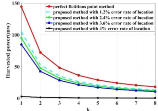
Fig. 2 The harvested power of userkby various user number.
where, rmrepresents the distance between the current ele- ment andr0k. Without loss of generality, we assume thatrm
increases by unit. According to Vieta theorem and Eulerian theories, we can obtain (8). So, the estimated error of posi- tion for user can also affect the received power. For∆k=0†, (8) becomesηkPt 1
|r0−rk|4
π2
6 −122
. This can be shown to be the maximum power that can be harvested with the position of userk. The harvested power at userkis a strictly increas- ing function of the total transmitter powerPt, but a strictly decreasing function of the fourth power of the distance.
3. Numerical Results
We present simulation results to validate the performance of our proposed method. We set M = 32×32, K = 4, Pt = 30dbm, fc = 20GHzandηk = 0.9,k ∈ {1,2,3,4}.
In addition, each pick-up head is located at the one top cor- ner of the aperture at intervals of 15 cm, corresponding to an electrical size of 10λat 20G,τ =0.12mm. The parameter length L of the element is 15 mm. φ0 = 0, φ1 = π/3 and φ2 = −π/3 can be obtained by simulations with CST. We begin our analysis with the above WPT scenario. Figure 2 depicts the harvested power of user k by various user num- ber with different error rate of location by 1.2%, 2.4%, 3.6%
and 4%. It is observed that the smaller error rate of location is, the higher the energy collected by the receiver is. What’s more, the error rate of location is too high to collect effective energy because the position of the receiver deviates from the focus area. In brief, the proposed method has vital perfor- mance loss than the perfect fictitious point method. How- ever, the proposed method can support for real-time mobile WPT for multiply users and has low actual cost. From the figure, we also can obtain that the effect of error rate of lo- cation is weakening with the increase of K, which because of energy dispersion for multiply users.
4. Conclusion
In this paper, we investigated a novel WPT scheme based on
†This hypothesis can be applied to some scenarios, such as short-range high-precision positioning and known user location, etc.
LETTER
1931
machine vision and reconfigurable holographic metasurface aperture in the Fresnel region. It has been shown that the proposed scheme has the same effect as traditional method.
However, the proposed method can transmit energy for mul- tiply mobile users simultaneously without any information feedback. The analytical results demonstrate the ability of proposed method to exhibit high fidelity effect even when serving multi-users.
Acknowledgments
This work was supported by National Natural Science Foun- dation of China (U1804148).
References
[1] H. Sun, H. Lin, F. Zhu, and F. Gao, “Magnetic resonant beamform- ing for secured wireless power transfer,” IEEE Signal Process. Lett., vol.24, no.8, pp.1173–1177, Aug. 2017.
[2] G. Lipworth, J. Ensworth, K. Seetharam, D. Huang, J.S. Lee, P.
Schmalenberg, T. Nomura, M.S. Reynolds, D.R. Smith, and Y.
Urzhumov, “Magnetic metamaterial superlens for increased range wireless power transfer,” Sci. Rep., vol.4, 3642, 2014.
[3] D.R. Smith, V.R. Gowda, O. Yurduseven, S. Larouche, G. Lipworth, Y. Urzhumov, and M.S. Reynolds, “An analysis of beamed wire- less power transfer in the fresnel zone using a dynamic, metasurface aperture,” J. Appl. Phys., vol.121, p.014901, 2017.
[4] F. Tofigh, J Nourinia, M. Azarmanesh, and K.M. Khazaei, “Near- field focused array microstrip planar antenna for medical applica- tions,” IEEE Antennas Wireless Propag. Lett., vol.13, pp.951–954, 2014.
[5] M. Ettorre, M. Casaletti, G. Valerio, R. Sauleau, L.L. Coq, S.C.
Pavone, and M. Albani, “On the near-field shaping and focusing ca- pability of a radial line slot array,” IEEE Trans. Antennas Propag., vol.62, no.4, pp.1991–1999, 2014.
[6] W. Luo and L. Xu, “Wireless power transfer in the radiative near- field using a reconfigurable holographic metasurface aperture,” 2018 IEEE International Conference on Communications (ICC), pp.1–5, Kansas City, MO, 2018.
[7] O. Yurduseven, D.L. Marks, J.N. Gollub, and D.R. Smith, “Design and analysis of a reconfigurable holographic metasurface aperture for dynamic focusing in the Fresnel zone,” vol.5, pp.15055–15065, 2017, DOI: 10.1109/ACCESS.2017.2712659
[8] G. Lipworth, N.W. Caira, S. Larouche, and D.R. Smith, “Phase and magnitude constrained metasurface holography at W-band frequen- cies,” Opt. Express, vol.24, no.17, pp.19372–19387, 2016.
[9] MACOM MA4AGBL912 PIN Diode, https://cdn.macom.com/ datasheets/MA4AGBLP912.pdf
[10] Z. Zhang, “A flexible new technique for camera calibration,” IEEE Trans. Pattern Anal. Mach. Intell., vol.22, no.11, pp.1330–1334, 2000.
[11] F. Liu, O. Tsilipakos, A. Pitilakis, A.C. Tasolamprou, M.S. Mir- moosa, N.V. Kantartzis, D.-H. Kwon, M. Kafesaki, C.M. Souk- oulis, and S.A. Tretyakov, “Intelligent metasurfaces with continu- ously tunable local surface impedance for multiple reconfigurable functions,” Phys. Rev. Appl., vol.11, no.4, p.044024, 2019.