-50 -40 -30 -20 -10
7 8 9 10 11 12 13 14 15
Frequency (GHz) S21 (dBm)
Development of Microwave Imaging Technology
Yamaguchi, S., Kitade, N. (Kansai Univ.) Nagayama, Y., Nishimura, T., Yoshinaga, T.
Kuwahara, D. (Tokyo Tech.)
Teranishi, M. (Hiroshima Inst. of Tech.) Iwama, N. (Daido Univ.)
Kogi, Y. (Fukuoka Inst. of Tech.) Mase, A. (Kyushu Univ. KASTEC)
Microwave Imaging Reflectometry (MIR) and Electron Cyclotron Emission Imaging (ECEI) are under development for three-dimensional (3-D) measurement of local electron density and temperature in magnetically confined plasma. These microwave imaging diagnostics are helpful for undisturbed observation of various plasma behavior, such as plasma turbulence, magnetic reconnection and magnetohydrodynamic instability.
Development of the 3-D diagnostics is expected to bring new findings to the plasma physics. A combined system of MIR and ECEI is developed in Large Helical Device (LHD). MIR illuminates cutoff layers by using plane wave with the frequency of 50 - 75 GHz in LHD, and the cutoff layers reflect the illumination plane wave. The reflected wave is focused by using a imaging optics, and
“microwave image” appears at the focal plane. The microwave image shows the perturbation of local electron density on the cutoff layers. The microwave image can be captured by “microwave camera” of a two-dimensional array of horn antennas with a multi-channel radiometer.
When a spatial wavelength of the perturbation on the reflection surface is in the same order of or less than the wavelength of the illumination wave, the reflected wave is strongly diffracted and diverged. As the diameter of the main focus lens of imaging optics is finite, the scattered (reflected) wave is only partially focused. This causes an ambiguous microwave image of the fine structure.
Microwave Computer Tomography (CT) techniques has better spatial resolution than MIR. Microwave CT is based on the reflection CT method. From complex reflected signals contrast function (complex dielectric constant) is reconstructed as the 3-D image of the target.
Microwave CT is used in pulse radar diagnostics by using the electromagnetic wave or the ultrasonic wave for non- destructive diagnostics of reinforced concrete structure.
Conventional CT method is utilized for the measurements of soft X-ray, bolometer, Electron Cyclotron Emission radiometer in plasma diagnostics, and they are based on the transmission measurement of absorption or self-emission.
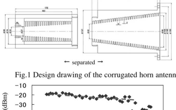
Microwave CT system is developed from MIR system of LHD and TPE-RX. A Voltage Controlled Oscillator (VCO) is used as the illumination source, the output frequency can be tuned by the dc voltage input from 8 to 14 GHz. When the output frequency is multiplied by six (48 to 84 GHz), the microwave circuit is basically same as the new MIR system of LHD. The development of the microwave CT is feedback to the MIR system. A corrugated horn antenna is developed in Kansai university for plane wave illumination. The antenna is a linear- tapered conical horn with a narrow flare angle and
corrugations inside it as shown in Fig. 1. The horn antenna has a symmetrical radiation pattern, high gain and low spillover. The antenna launches the plane beam to a dielectric material target with the beam width of φ90 mm.
The plane wave illumination enables to simplify the CT analysis. Its calculation time can be much reduced by using the Born approximation in which the plane wave is weakly scattered in the target.
As the corrugated structure is difficult to manufacture, the antenna is axially separated into two parts.
The antenna is made of aluminum and it is machined by a Numerical Controlled (NC) lathe in NIFS workshop. The corrugated structure of the aperture part can be machined by the lathe, but the structure of the waveguide connection part is too narrow and too deep to manufacture. The corrugated structure of the latter part is made by stacking of thin circular plates with a central hole. They consist of twenty-four “ridge plates” and twenty-three “slot plates”.
The thickness of the ridge plate is 2.0 mm (the ridge width), and the thickness of the slot plane is 4.0 mm (the slot width). Different diameters of the central hole between the ridge and slot plates decides the slot depth. The diameter of the central hole on the ridge plate decreases from φ90 mm (at the antenna aperture) to φ24 mm (at the feeding waveguide). The flare angle decides the radiation angle of the horn antenna. In design, it is estimated to be less than 5 degrees at -10 dB down from the peak power.
Figure 2 shows the measured bandwidth of the corrugated horn antenna. The antenna is used in a transmitter (Tx) mode, and a X-band rectangle waveguide antenna receives the radiation from the Tx antenna. The scanning frequency is between 7.9 and 14.2 GHz, which is the maximum range of the VCO. The received microwave passes through -20 dB attenuator and it inputs into the spectrum analyzer of ADVANTEST R3271A.
The frequency spectrum shows the wideband performance of the antenna between 8 and 13 GHz. Some cable loss appears in the higher frequency range, and a sharp drop occurs at the 13.3 GHz. The result shows that the corrugated horn antenna can be utilized in the full X-band frequencies of 8 - 12 GHz. By using it the initial experiment of the microwave CT system will be done in summer 2010.
Fig.1 Design drawing of the corrugated horn antenna.
Fig.2 Frequency spectrum of the corrugated horn antenna.
separated
169
§20. Development of Microwave Imaging Technology
Yamaguchi, S., Kitade, N. (Kansai Univ.), Nagayama, Y., Nishimura, T., Yoshinaga, T., Kuwahara, D. (Tokyo Tech.),
Teranishi, M. (Hiroshima Inst. of Tech.), Iwama, N. (Daido Univ.),
Kogi, Y. (Fukuoka Inst. of Tech.), Mase, A. (Kyushu Univ. KASTEC)