Repetitive short‑pulsed generator using MPC and Blumlein line
journal or
publication title
Digest of Technical Papers‑IEEE International Pulsed Power Conference
volume 2003
page range 657‑660
year 2003‑06
URL http://hdl.handle.net/2298/9711
doi: 10.1109/PPC.2003.1277795
REPETITIVE SHORT-PULSED GENERATOR USING MPC AND BLUMLEIN LINE
T. Sakugawa
ξ, D. Wang, K. Shinozaki, T. Namihira, S. Katsuki and H. Akiyama Graduate School of Science and Technology, Kumamoto University,
Kurokami 2-39-1,Kumamoto 860-8555, Japan
Abstract
Recently, repetitive pulsed power generators using magnetic pulse compression (MPC) and semiconductor switches have been developed. A repetitive short-pulsed generator for an ozonizer was studied and developed.
In this work, the short-pulsed generator consists of a controller, a command charger, a high-speed thyristor, a MPC and a Blumlein line. The controller and the com- mand charger are able to control the charging voltage to the MPC and the pulse repetition rate. The high-speed thyristor, which was improved in switching speed for the pulsed power applications, generated the primary pulse.
The MPC has single stage pulse compression circuit us- ing a pulse transformer and a saturable transformer. The saturable transformer has two functions, a step-up trans- former and a magnetic switch. The Blumlein line is the final stage of the short-pulsed generator. The Blumlein line is three-coaxial geometry, which has an external electrode diameter of 110 mm, a middle electrode diame- ter of 20 mm, an internal electrode diameter of 4 mm, and a length of 500 mm. The short-pulsed generator which has an output voltage of about 65 kV, pulse repeti- tion rate of 150 pulses per second (pps) and a pulse dura- tion of less than 10 ns was used to generate ozone..
The results of ozone production using the short-pulsed generator and a simple coaxial electrodes are reported.
The attained concentration of ozone was 18 g/m
3.
I. INTRODUCTION
In recent years, researches on practical industrial ap- plications of repetitive pulsed power generated by a MPC have been increased. These researches have fo- cused on lasers for a long time. In particular, the excimer laser, which is used as a microlithographic light source in semiconductor fabrication, requires a high repetition rate, a high stability, and a long lifetime. Therefore, most of the excimer lasers for microlithography use a semicon- ductor switch and a MPC for their exciter [1, 2]. More- over, the applications to environmental fields involving the decompositions of harmful gases and the generation of ozone utilizing pulsed power discharges have been studied [3, 4]. In these applications, the repetitive opera- tion and the long lifetime are also necessary for the pulsed power generators.
Heretofore, the ozone generations by a pulsed power supply, which used a semiconductor switch and a MPC, have reported [4, 5]. In these papers, the pulse width of the output voltage from the pulsed power generator was about 90 ns. However, the duration of high voltage pulse needs to be short enough to prevent corona-to-arc transi- tion. Furthermore, the pulsed power generator with short-pulse width is necessary. Nevertheless, it is diffi- cult to generate the short-pulsed voltage less than 10 ns using the MPC.
In order to generate the short-pulsed voltage which is shorter than the output voltage from the MPC, a Blum- lein line was added on the output side of the MPC. This was called as the short-pulsed generator. In the present work, the characteristics of the output voltage from and the ozone generation by the short-pulsed generator are reported.
II. EXPERIMETAL APPARATUS AND PROCEDURES
A. MPC and Semiconductor Switch
A schematic diagram of the MPC is shown in Fig. 1.
The MPC consists of a semiconductor switch, a pulse transformer (PT), a saturable transformer (ST), saturable inductors (SI
0, SI
1), and low inductance capacitors (C
0, C
1). The high-speed gate turn off thyristor (GTO, H10D33YFH, Meidensha Corp., Japan) was used as a switch of the primary circuit. The GTO thyristor was improved to decrease switching energy loss for pulsed power applications [6]. Table 1 shows the specifications of the GTO thyristor. A Fe-based nanocrystalline mag- netic core (FT-1H, Hitachi metals Ltd, Japan) was used as the coupling core of the ST. The ST has two functions, step-up transformer and magnetic switch [6, 7]. The nanocrystalline soft magnetic alloys were used as the magnetic switches (ST, SI
0) and the PT. The magnetic and the physical characteristics of the magnetic alloys are shown in Table 2. The voltage gain of the ST is 8 (winding ratio, primary : secondary = 1 : 8), and the overall step-up ratio which is including both of PT and ST is 24. The capacitances of C
0and C
1are 800 nF and 1nF, respectively. A command charger that can provide a charge whenever the capacitor C
0requires was employed.
The GTO thyristor turned on with the current I
0, and then
ξ
Email: [email protected]
SI
0saturated (turned on) immediately after the assist time. The current I
0with duration of 1.2 µs flowed in the primary circuit. As a result, C
1is charged to a high- voltage through the step-up transformers (PT and ST). In this time, SI
1performed as a diode, which acts as an in- ductor to charge C
1, also acts as an inductor to block the discharge of C
1. Finally, the pulse current with the dura- tion of about 90 ns was generated after saturating the ST.
On the other hand, the Blumlein line was charged rapidly by the output current from the MPC.
Fig. 2 shows the dependence of the peak voltages from the MPC on the charging voltage to C
0. In Fig. 2, a 100 Ω resistor was used instead of the Blumlein line in Fig. 1.
Fig. 2 shows that the peak voltages are in proportion to the charging voltages.
Figure 1. Schematic diagram of MPC.
Table 1. Specifications of high-speed GTO thyristor.
Repetitive peak off-state voltage : 3300 V Surge on-state current : 5000 A Critical rate of on-state current : 8000 A/ μ s
Gate current : 50 A
peakExternal dimension : φ 79 × 26.5 mm
Weight : 600 g
Table 2. Magnetic and physical characteristics of nanocrystalline magnetic core.
Saturation induction B s : 1.35 T Remanent flux density B r : 1.22 T Coercive force H c : 0.8 A/m Saturation magnetostriction λ s : +2.3 x 10
-6Curie temperature T c : 570 ℃ Resistivity ρ : 1.1 μΩ -m
15 20 25 30 35 40
1.5 2 2.5 3
Pe ak v o lt ag e [k V]
C
0charging voltage [kV]
Figure 2. Peak voltage of MPC as a function of the charging voltage to C
0.
B. Short-pulse generator
Fig. 3 shows the schematic diagram of the short- pulsed generator. The MPC is used as a charging genera- tor for the Blumlein line. The Blumlein line consisted of coaxial cylindrical tubes, filled up insulated oil, and a spark gap switch (GS). An inductor L is used as a charg- ing inductor for Blumlein line. The inductance of L was 2 µH.
Fig. 4 shows the structure of the Blumlein line. The GS was filled up with SF
6gas in the rage of 0.1 to 0.35 MPa. The Blumlein line had three-coaxial geometry, which had an external electrode diameter of 110 mm, a middle electrode diameter of 20 mm, an internal elec- trode diameter of 4 mm, and a length of 500 mm. The calculated impedance, capacitance and inductance of the Blumlein line were 130 Ω, 38 pF and 640 nH, respec- tively. The output voltage from the short-pulsed genera- tor was successfully as same as the charging voltage to it.
The peak of the charging voltage was controlled by the pressure of SF
6gas.
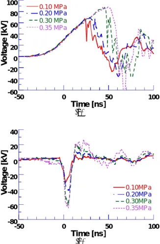
Fig. 5 shows the typical waveforms of the charging voltage to and the output voltage from the short-pulsed generator for different gap pressures. In Fig. 5, a 100 Ω resistor was used as a road of the short-pulsed generator.
It will be observed from Fig. 5 that the peak voltage from the short-pulsed generator increased with increasing the pressure of SF
6gas. The highest peak voltage was ap- proximately 65 kV with 7 ns width at 0.35 MPa of SF
6pressure.
L o a d
GS
Blumleinline MPC L
Figure 3. Schematic diagram of the short-pulsed genera- tor.
Blumlein line
C0
GTOThyristor ST
C1
SI1
SI0 I1
I2
I0 Command Charger
PT
658
①
②
③
④
⑤
⑥
⑦
⑧
⑨
⑩ ⑪
⑮
⑯
①
②
③
④
⑤
⑥
⑦
⑧
⑨
⑩ ⑪
⑮
⑯
⑫
Spark gap switch Internal electrode Middle electrode External electrode
Transmission line Output Charging feed throw
Figure 4. Structure of the Blumlein line.
-60 -40 -20 0 20 40 60 80 100
-50 0 50 100
0.10 MPa 0.20 MPa 0.30 MPa 0.35 MPa
Vo lt a g e [kV ]
Time [ns]
(a)
-80 -60 -40 -20 0 20 40
-50 0 50 100
0.10MPa 0.20MPa 0.30MPa 0.35MPa
Vo lt a g e [kV ]
Time [ns]
(b)
Figure 5. Typical waveforms of the charging voltage to (a) and the output voltage from (b) the short-pulsed gen- erator for different SF
6gas pressures.
C. Ozone production using the short-pulsed generator The experimental set-up is shown in Fig. 6. The pro- duction of ozone using the short-pulse generator was examined. The set-up consisted of a cylinder of oxygen, the discharge reactor, an ozone monitor and the short- pulsed generator. A coaxial simple electrodes was used
as the discharge reactor. A tungsten wire having 1 mm of diameter was placed concentrically in a brass cylinder having 50 mm of inner diameter and 200 mm of length (in Fig. 7). The short-pulsed voltage was applied to the inner wire. The outer cylinder was grounded. The purity of the oxygen cylinder was 99.5 %. The gas flow rate and the ozone concentration were monitored by a flow- stat meter and an ozone monitor based on the ultraviolet ray absorption, respectively. The gas flow rate was fixed at 1.0 l/min.
The applied voltage to and the discharge current through the reactor were measured using a resistive volt- age divider (1Ω/20kΩ), which was connected between the center wire and the ground, and a current monitor (Model 2878, Pearson Electronics, USA), respectively.
Short pulsed Generator O2
O3Monitor
OSC
Activated carbon Reactor
Flow meter
Figure 6. Experimental set-up for production of ozone
O
2O
3Center wire electrode
Outer grounding electrode
Figure 7. Discharge reactor configuration.
III. RESULTS OF
OZONE PRODUCTION EXPERIMENT Fig. 8 shows typical waveforms of the applied voltage to and the discharge current through the reactor. It will be observed that the FWHM of the applied voltage was about 6 ns, while that of the discharge current was about 8 ns.
The results of the ozone production using the short-
pulsed generator are shown in Fig. 9. It will be observed
that the concentration of ozone depended on the charging
energy to C
0.
-120 -80 -40 0 40
-1200 -800 -400 0 400
-30 -20 -10 0 10 20 30
Voltage Current
Time [ns]
Figure 8. Typical waveforms of the applied voltage to and the discharge current through the reactor.
0 5 10 15 20
0 5 10 15 20 25 30 35 40
O3
O
3co n c en trati o n [g /m ]
3C
0charging energy [J/s]
Figure 9. Dependence of ozone concentration on input energy to C
0of the Short-pulsed generator.
IV. SUMMARY AND FUTURE DEVELOPMENT PLANS Stable operation of the short-pulsed generator at sev- eral hundreds pps was succeed. The output voltage had the peak value of 65 kV with less than 10 ns width. The ozone production using the short-pulsed generator and a coaxial electrodes was done. The attained concentration of ozone was 18 g/m
3. This means that the short-pulsed generator is able to be a power supply to generate ozone.
Although the obtained concentration of ozone was not superior to that of using a silent discharge ozonizer, the short-pulsed voltage has a great potential for an im- proved short-pulsed generator by choosing the certain circuit and the characteristics of the reactor.
The future plans should be to increase the pulse repeti- tion rate and maximum output voltage, and to employ the magnetic switch instead of the gap switch of the Blum- lein line. In addition, it is eager to replace the Blumlein line to a pulse forming network.
REFERENCES
[1] W. Partlo, R. Sandstrom, I. Fomenkov, “A low cost of ownership KrF excimer laser using a novel pulse power and chamber configuration” , The Interna- tional Society for Optical Engineering-SPIE , Vol.
2440, p.90, 1995
[2] H. Mizoguchi, O. Wakabayashi, T. Aruga, T. Saku- gawa and T. Koganezawa, “High power KrF excimer laser with a solid state switch for microlithography”, The International Society for Optical Engineering- SPIE, Vol. 2726, pp. 813-840, 1996
[3] T. Namihira, S. Tsukamoto, D. Wang, S. Katsuki, R.
Hackam, H. Akiyama, Y. Uchida and M. Koike, “Im- provement of NOx removal efficiency using short width pulsed power”, IEEE Transactions on Plasma Science, Vol. 28, No. 2, pp.434-442, 2000
[4] W. J. M. Samaranayake, Y. Miyahara, T. Namihira, S.
Katsuki, T. Sakugawa, R. Hackam and H. Akiyama,
“Pulsed streamer discharge characteristics of ozone production in dry air” IEEE Transactions of Dielec- trics and Electrical Insulation, Vol. 7, No. 1, pp.254- 260, 2000
[5] T. Namihira, K. Shinozaki, S. Katsuki, R. Hackam, H.
Akiyama and T. Sakugawa, “Characteristics of ozonizer using pulsed power,” in Proc. 13th Pulsed Power Conf., pp. 1090-1093, 2001
[6] T. Sakugawa, H. Akiyama, “An all-solid-state pulsed power generator using a high-speed gate-turn-off thy- ristor and a saturable transformer”, Electrical Engi- neering in Japan, Vol. 140, No. 4, pp.17-26, 2002
[7] S. Nakajima, S. Arakawa, Y. Yamashita and M. Shiho,
“Fe-based nanocrystalline FINEMET cores for induc- tion accelerators”, in Proc. Nuclear Instruments and Methods in Physics Research A331, pp.318-322, 1993
660