INVITED PAPER
Special Section on Terahertz Waves Coming to the Real WorldHigh-Speed Coherent Transmission Using Advanced Photonics in Terahertz Bands
Atsushi KANNO†a), Pham TIEN DAT†, Norihiko SEKINE†, Iwao HOSAKO†, Tetsuya KAWANISHI†,††, Yuki YOSHIDA†††,Members,andKen’ichi KITAYAMA†††,Fellow
SUMMARY A terahertz-wave communication system directly con- nected to an optical fiber network is promising for application to future mobile backhaul and fronthaul links. The possible broad bandwidth in the terahertz band is useful for high-speed signal transmission as well as radio-space encapsulation to the high-frequency carrier. In both cases, the low-latency feature becomes important to enhance the throughput in mobile communication and is realized by waveform transport technology without any digital-signal-processing-based media conversion. A highly precise op- tical frequency comb signal generated by optical modulation and the vector signal demodulation technology adopted from advanced optical fiber com- munication technologies help perform modulation and demodulation with impairment compensation at just the edges of the link. Terahertz wave, radio over fiber, waveform transport, coherent detection, multilevel modu- lation, radio on radio.
key words: terahertz wave, radio over fiber, waveform transport, coherent detection, multi-level modulation, radio on radio
1. Introduction
Connectivity to the Internet is now indispensable for access- ing information and knowledge, and thus, for enhancing the quality of human life. Traditionally, a high-speed connec- tion has been established by a wireline connection: a cop- per telephone line and an optical fiber. From the viewpoint of advanced optical fiber communication technologies, the speed of the link in a single channel has achieved 100 Gb/s for metro and core networks, and now, 400-Gb/s/ch optical transport technology is being developed for next-generation high-capacity networks[1]–[3]. Additionally, in an access network, optical fiber cables are deployed to the home:
a fiber-to-the-home (FTTH) scheme under a passive opti- cal network configuration. Thus, home users can have a wireline connection to the Internet with a speed of up to 1 Gb/s[4], [5]. However, as wireline-based communica- tion limits service areas, and thus, limits ubiquitous con- nectivity to the network, mobile communication based on advanced radio technology is being dramatically developed to enhance connectivity. Now, Long Term Evolution (LTE) technology and its advanced form (LTE-advanced) service
Manuscript received July 15, 2015.
Manuscript revised August 16, 2015.
†The authors are with the National Institute of Information and Communications Technology, Koganei-shi, 184–8795 Japan.
††The author is also with the Faculty of Science and Engineer- ing, Waseda University, Tokyo, 169–8555 Japan.
†††The authors are with the Graduate School of Engineering, Osaka University, Suita-shi, 565–0871 Japan.
a) E-mail: [email protected] DOI: 10.1587/transele.E98.C.1071
users with a connection speed on the order of 100 Mb/s; the speed achieved is comparable to the speed of conventional FTTH[6],[7]. For next-generation mobile technology be- yond LTE-advanced, so-called 5G, the aim is a connection speed of 10 Gb/s to subscribers; the speed will be compa- rable or faster than that for the FTTH[8]–[10]. To support such high-speed communication, a base transceiver station (BTS) for mobile communication should be connected to an optical fiber network to support its high-capacity mobile traffic as a backhaul link or even a fronthaul link. How- ever, in 5G, the coverage for each BTS becomes smaller than that for LTE because of the enhancement in the con- nection throughput. In this scenario, a large number of BTSs will be installed in the field; many optical fiber cables will be deployed. However, as the cables cannot be deployed somewhere owing to geographical and cost issues, wireless connection technology to the BTSs as mobile backhaul and fronthaul links is strongly desired. Actually, the wireless mobile backhaul has been already evaluated by millimeter- wave radio communication technology with a capacity on the order of 1 Gb/s; however, it is not sufficient for even near future LTE-advanced[11].
Terahertz-wave radio communication technology is promising for the realization of a high-speed backhaul and fronthaul connection by a wireless feature owing to its high carrier frequency and its broadness of available band- widths[12], [13]. Moreover, 5G backhaul and fronthaul links require an ultrahigh-speed feature and a low trans- mission latency compared to the conventional fronthaul us- ing digitized communication technology, such as a 10-Gb/s common public radio interface (CPRI) and an open radio equipment interface (ORI)[14],[15]. The broad bandwidth of the terahertz radio meets the demands, and it is possible to provide a high-speed link>10 Gb/s when the available bandwidth is greater than 10 GHz. However, as the atmo- spheric attenuation coefficient in the band is estimated to be 3 dB/km under standard atmospheric conditions without any rain, the possible transmission distance could be shorter than the radio link by conventional microwave- and millimeter- wave radio[16],[17]. In addition, the seamless convergence between the optical and radio networks is demanded to en- hance the network functions such as virtualization and opti- mization of the network resources in future network config- urations (Fig. 1)[18].
Radio over fiber (RoF) technology can meet the de- mands for realizing feeder technology of the terahertz signal Copyright c2015 The Institute of Electronics, Information and Communication Engineers
Fig. 1 Concept of a terahertz backhaul and fronthaul directly connected to an optical fiber network for future mobile networks.
to a suitable area and seamless connection to the optical net- work[19]–[21]. Optical-to-electrical (O/E) and electrical- to-optical (E/O) conversion technologies provide direct con- version between the optical and terahertz radio signals with- out any processing latency, and its signal speed is much faster than 10 Gb/s[22]–[25]. IIn addition, advanced optical digital coherent detection can compensate for transmission impairments of the signal in the optical domain, even in the terahertz domain; a waveform of the signal is transported over the fiber and the air between a transmitter (Tx) and a receiver (Rx)[26]. No conventional media conversion by digital signal processing (DSP) is required in the O/E and E/O conversions; thus, the possible latency of the transmis- sion could be reduced.
In this paper, we propose and demonstrate high-speed terahertz signal transmission by advanced photonics tech- nology such as digital optical coherent detection and op- tical frequency comb (OFC) generation. An OFC gener- ator (OFCG) configured with optical modulation provides a terahertz-capable optical two-tone signal with low phase- noise characteristics. In Sect. 2, the details of optical signal generation for terahertz radio are presented. DSP-assisted coherent detection can receive a 40-Gb/s-class vector signal such as quadrature phase-shift keying (QPSK) generated by an optical subharmonic IQ mixer (Sect. 3). For a reduction in the latency and encapsulation technology of conventional microwave services, a terahertz radio employing radio on radio (RoR) technology is evaluated in Sect. 4. Finally, a transmission distance evaluation of the terahertz radio is dis- cussed in Sect. 5.
2. Optical Terahertz Signal Generation
For seamless conversion from the optical signal to the ter- ahertz signal, optical signal generation is key with a high frequency stability in order to follow radio regulations. In addition, it is also important to maintain compatibility in the signal generator, especially in the port configurations, with existing modulators designed for conventional microwave
Fig. 2 Configuration of an optical subharmonic (IQ) mixer.
and millimeter waves. In the following sections, we discuss the modulator configuration by photonics and the enhance- ment in the signal-to-noise ratio (SNR).
2.1 Configuration of an Optical Subharmonic Mixer To maintain compatibility of connection port configuration with conventional modulators, we propose the optical sub- harmonic mixer (SHM) configuration shown in Fig. 2[27], [28]. This consists of an OFCG, an optical filter bank (OFB), an optical modulator, and a high-speed photomixer (PM) based on a unitraveling-carrier photodiode[29],[30].
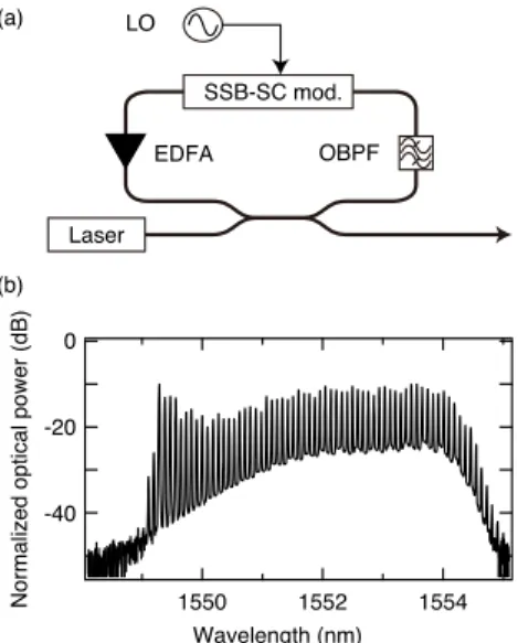
The OFCG generates an optical frequency comb signal with a bandwidth broader than the required frequency in the ter- ahertz band. It should be noted that the generated OFC di- rectly affects the quality of the terahertz signal, such as the frequency stability and phase-noise characteristic. From this point of view, a modulator-based frequency comb generator is applicable because this OFCG has a frequency separa- tion provided by a microwave synthesizer driving the mod- ulator; that is, the stability could be comparable to that of the synthesizer with an order of 1 ppm. In this paper, for a proof-of-concept demonstration, we demonstrate a recir- culating frequency shifter in an amplified optical fiber loop for OFC signal generation (Fig. 3)[31],[32]. An optical fre- quency shifter, which is based on an optical single-sideband (SSB) suppressed-carrier (SSB-SC) modulator connected to a local oscillator (LO), changes an optical frequency of the input optical signal with the frequency of the LO sig- nal[33]. In the amplified loop, this frequency-shifting pro- cess is performed many times by an erbium-doped fiber am- plifier (EDFA) compensating for the insertion loss of the fre-
Fig. 3 (a) Block diagram of a recirculating frequency shifter, and (b) its generated optical frequency comb signal.
quency shifter; thus, the resulting OFC signal is output from the optical coupler. Figure 3 (b) shows an OFC signal gener- ated with the LO for the frequency shifter operated at a fre- quency of 10 GHz using a laser operating at a wavelength of 1548.3 nm. Clear comb separation with a broad bandwidth of 5 nm, which corresponds to approximately 600 GHz, is observed. This bandwidth is limited by an optical bandpass filter (OBPF), which has an optical pass-bandwidth of 5 nm, located in the fiber loop, which suppresses unwanted comb lines and amplifies spontaneous emission (ASE) noise. As the wavelength increases, the noise level also gradually in- creases according to the ASE noise generated by the EDFA.
This might cause a degradation in a resulting SNR of the ter- ahertz signal. The SNR enhancement method is described in the next subsection.
In the optical SHM, an OFB splits the OFC signal into two optical components with the frequency separation of the required terahertz carrier. An arrayed waveguide grat- ing structure is useful for this purpose as the filter bank. The split signals are used for modulation and an optical refer- ence. An optical modulator is utilized for modulation; for simple intensity modulation (IM), a simple Mach–Zehnder interferometer-type optical modulator is applicable. An op- tical phase modulator and optical in-phase/quadrature (IQ) modulator are also applicable for phase and vector modula- tion with advanced modulation formats, respectively. The modulated signal and optical reference are combined by an optical coupler; then, a PM performs frequency downcon- version by the heterodyne process to generate the modu- lated terahertz signal[34]. In the optical SHM or subhar- monic IQ mixer (SHIQM), the configuration of the input and output ports (LO input, data input, and modulated sig- nal output) is just the same as a conventional modulator used in microwave communication systems. Therefore, the opti- cal SHM/SHIQM could be easily interchanged from con- ventional systems.
Fig. 4 Block diagram of an SNR enhancement system using an injection- locked laser.
Fig. 5 (a) Observed optical spectra and (b) phase noise spectra with (black) and without (gray) injection locking. The phase noise spectra for the LO signals for an OFCG and SHM LO signal in a receiver are shown for reference (dashed).
2.2 Signal-to-Noise Ratio Enhancement by Injection Locking
An enhancement in the SNR of an optical two-tone signal generated by the OFCG described above can directly in- crease the SNR of the resulting terahertz signal. There are some techniques to increase the SNR: stimulated Brillouin scattering (SBS) in the optical fiber and injection-locking to a free-running laser[35],[36]. SBS is a possible technique for regenerating the signal by the nonlinear effect in the op- tical fiber. In general, a narrow bandwidth of several tens of megahertz in SBS provides a high suppression ratio of unwanted components; a high SNR could be obtained. On the contrary, an injection-locked laser also regenerates the high-SNR optical signal locked to a seed signal with a low complexity. In this paper, the enhancement in the SNR by the injection locking technique with a seed OFC signal is evaluated.
Figure 4 shows the configuration of the setup for sig- nal regeneration by injection locking. After the filter bank, the optical component picked from the OFC signal is input into a free-running Fabry–Per´ot laser diode (FPLD) passed through an EDFA, an optical circulator, and a polarization
seed signal, the optical SNR is increased by at least 10 dB.
In addition, there is no degradation in the SSB phase noise shown in Fig. 5 (b). These results show that the SNR en- hancement technique using an injection-locked laser is ca- pable of terahertz signal generation.
3. High-Capacity Transmission Using Baseband Mod- ulation
For the wireless backhaul, the connection links between the BTSs, and/or the entrance network and the BTSs, high- speed terahertz signal generation and its transmission are re- quired with a capacity greater than 10 Gb/s. In this scenario, baseband modulation by the optical SHIQM with assistance of DSP can provide a signal with a high spectral efficiency for transmission over the fiber as well as air[37].
3.1 Concept of DSP-Aided Coherent Detection
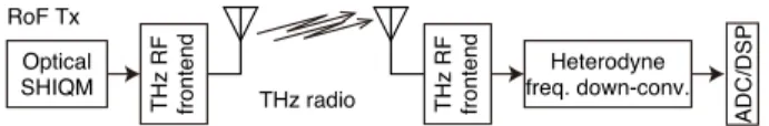
Figure 6 shows the concept of DSP-aided coherent transmis- sion based on RoF technology. In the Tx (RoF Tx), a “radio- friendly” signal is synthesized by the optical SHIQM for di- rect radiation to air. Generally, the signal radiated to air as a radio should be consistent with the quality limited by ra- dio regulations. On the other hand, available active devices such as an amplifier have a bandwidth of 30–60 GHz in 300- GHz band, which corresponds to a fractional bandwidth of 10–20% in general. As the available bandwidth for the com- munication system is limited by these devices in each chan- nel, a spectrally efficient signal should be synthesized for 100-Gb/s-class signal transmission. In this scenario, a vec- tor modulator (optical SHIQM) is employed for terahertz signal generation. In the O/E conversion by the PM, the ter- ahertz signal is radiated and transmitted over the air. At the Rx, a heterodyne-detector-based coherent frequency down- conversion block reproduces an intermediate frequency (IF) component from the received terahertz signal because of the limited bandwidth of the analog-to-digital converter (ADC).
After capturing the signal by the ADC, DSP proceeds with carrier recovery including frequency downconversion to the baseband, phase noise compensation, equalizing, and de- modulation, which is similar to the DSP implemented for advanced optical digital coherent detection. Therefore, DSP for the optical system can be adopted for the terahertz re- ceiver with small modifications. In this system, the DSP compensates for the transmission impairments over the fiber as well as those over air. In addition, a waveform including the modulation format, symbol rate, etc., is kept in the entire link. Therefore, the waveform is directly transported from the Tx to the Rx in any transmission media.
It should be noted that coherent detection based on het-
Fig. 7 Experimental setup for DSP-aided coherent QPSK signal trans- mission at 325 GHz.
erodyning can enhance the sensitivity of the receiver using a high-power LO signal; the sensitivity is key for terahertz radio communication because of its low transmitted power due to transmission attenuation. However, the frequency difference between the irradiated carrier and a free-running LO for the heterodyne detector produces intensity and phase fluctuations in the regenerated IF signals. Thus, the DSP for compensating for this carrier frequency offset (CFO) should be implemented in the receiver.
3.2 Experimental Setup
The experimental setup for high-capacity transmission with high-gain antennas is shown in Fig. 7. The optical SHIQM operates at 25 GHz as an LO generating a radio-friendly op- tical signal at a carrier frequency of 325 GHz with a QPSK signal whose symbol rate is 20–32 Gbaud. The seed signals for QPSK generation are provided by a two-channel pulse pattern generator with a pseudorandom bit stream (PRBS).
The generated optical signal is boosted by an EDFA, fol- lowed by an OBPF, for suppression of amplified sponta- neous emission noise. The amplifier optimizes the optical power level for input into a PM. The PM converts the op- tical signal (with a frequency separation of 325 GHz) to a 325-GHz terahertz-wave signal. An antenna with a gain of 46 dBi radiates the signal to air, and the antenna at the re- ceiver collects the transmitted signal. It should be noted that an offset parabolic antenna made from aluminum is used as the antenna for both the Tx and Rx[18]. An electrical SHM, operated at a 12.5-GHz LO signal, performs heterodyne fre- quency down-conversion from 325 GHz to 25 GHz. An IF amplifier optimizes the signal level for input into an ADC with a sampling speed of 160 Gs/s. A digital storage oscil- loscope is used as the ADC, and offline DSP compensates for transmission impairments and demodulation.
3.3 Demonstration
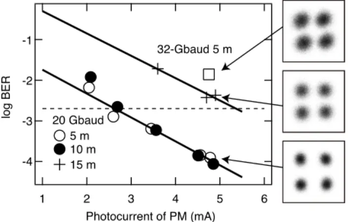
The observed bit error rates (BERs) are shown in Fig. 8.
The BERs for 5-m and 10-m transmissions are similar at 20 Gbaud and within the forward error correction (FEC)
Fig. 8 Observed bit error rates for various transmission distances and symbol rates. The constellation maps are also shown. The dashed line indicates the FEC limit of the BER of 2×10⁻³.
limit of the BER of 2×10⁻³using a 7% FEC overhead[38].
On the other hand, the under-15-m transmission with 20- Gbaud QPSK has some differences compared to the 10-m transmission. This is because a Fraunhofer distance be- tween the Fresnel and Fraunhofer zones, which corresponds to the border between the near and far fields, is described by 2D2/λ, whereDandλdenote the aperture of the antenna and the wavelength of the radio signal, respectively. In this study,Dandλwere approximately 8 cm and 1 mm; thus, the distance is estimated as 12 m[18]. This is the reason why the behavior of the BER for 10 m and 15 m seems quite dif- ferent. The observed penalty between the two ranges is esti- mated at 8 dB. The penalty between the 5-m and 15-m trans- missions, estimated using the Friis propagation equation, is approximately 4 dB. The difference between the estimated and observed values is possibly due to a misalignment of the antenna direction. Constellation maps of the received QPSK signal are also shown in Fig. 8. A clear symbol separation is exhibited during 20-Gbaud operation. It should be noted that the expected radio power at 300 GHz is approximately less than−13 dBm when the photocurrent is 5 mA owing to the specification sheet of the photomixer. By using a high- gain antenna pair, 20-Gbaud QPSK radio transmission can be performed, even if the output power is less than 100μW.
4. Low-Latency Transmission by Radio on Radio For application to the mobile fronthaul, which is a connec- tion between a signal processing unit and the remote ra- dio heads in the BTS, the transmission latency is key for the mobile network. Particularly in next-generation mo- bile networks, a centralized radio access network config- uration will be implemented on the basis of a centralized signal processing unit connected to a large number of re- mote radio heads by the fronthaul links. In this scenario, the fronthaul technology will be important. Generally, the radio access network is defined as the range between mod- ulation/demodulation and the user equipment (UE) includ- ing the transmission line. Thus, the latency in the fronthaul should be reduced in order to increase the throughput of
mobile communication. However, conventional fronthaul technology is based on digitized signal transmission by an on–offkeying (OOK); thus, an unavoidable processing la- tency in the signal processing unit and remote radio heads exists for signal conversion between the OOK signal and the highly spectrum-efficient signal in the mobile network.
In the optical domain, an analog RoF link has ultimately low invasiveness from/to existing radio services; thus, it is easy to realize by deploying fiber. To apply a similar radio-signal encapsulation scheme to the other radio carriers, the radio signal can be delivered to the desired location by a wireless network. This RoR system is capable of avoiding the radio interference between the delivered signal and the existing radio signals in the microwave bands, even if the signal is transmitted over air[39]–[41].
4.1 Concept of Radio on Terahertz over Fiber System An RoR in the terahertz band has a great advantage of the available bandwidth[42]. In conventional RoR, a carrier frequency is assumed in the millimeter-wave band, such as 60 GHz with a 9-GHz license-free bandwidth. On the other hand, the possible bandwidth will be greater than 10 GHz in the terahertz band; thus, the number of encapsulations of microwave services will increase. To generate the RoR signal in the terahertz band by photonics, an optical SHM is useful for analog modulation by the intensity modulation scheme (Fig. 9). The generated signal, the radio on tera- hertz over fiber (RToF) signal, is capable of transmission over the fiber and air by terahertz radio. In decapsulation of the microwave signal, a simple envelope detector in the ter- ahertz band as well as a terahertz mixer can regenerate the microwave signal without any DSP in the terahertz-to-radio (T/R) converter, i.e., a manner similar to the DSP-less me- dia conversion described in the sections above. Finally, the microwave radio is transported via an optical fiber and tera- hertz radio to a UE. In this configuration, the RToF system is applicable to the mobile fronthaul as well as radio sig- nal delivery to subscribers. To enhance the sensitivity of the T/R converter, a mixer with a free-running LO is applied for coherent detection. It should be noted that there are issues with the CFO compensation by DSP described in the section above. A self-homodyne detector in the terahertz band can be also applied with a high sensitivity and low phase-noise characteristics[43].
Particularly in radio interference, a terahertz radio might not affect existing microwave/millimeter-wave ser- vices and the possible existence of other terahertz radio ser- vices. This is because the terahertz radio link should be based on a beam-like link by high-gain antennas owing to its large atmospheric attenuation. Moreover, as the transmis- sion distance is limited for the same reason, an optimized cell/link design can mitigate interference.
The RoR described in this paper only focuses on encap- sulation and transport of the radio space in the microwave band to desired locations by the terahertz radio and optical fibers. For future millimeter-wave communication systems
Fig. 9 Conceptual diagram of a radio on an RoF system. The corresponding schematic spectra are also shown.
Fig. 10 Block diagram of the experimental setup for radio on a terahertz over fiber system with an LTE signal.
such as 5G, analog IF signal transport by the RToF technique is also applicable. In that configuration, the subcarrier mul- tiplexing technique in the electrical domain can aggregate many IF signals for transport to remote radio heads without any DSP in the media conversion.
4.2 Experimental Setup
Figure 10 shows the experimental setup for RToF signal transmission, which consists of four blocks: an optical SHM, a PM as an optical-to-terahertz converter, a Schottky barrier diode (SBD) as the envelope detector in a T/R con- verter, and a vector signal analyzer (VSA) as a microwave signal analyzer. In this study, we used an LTE down-link signal at a center frequency of 2.1 GHz with a bandwidth of 20 MHz as the signal under test. The microwave signal and an LO signal at a frequency of 12.5 GHz are input into an optical SHM based on an optical IM; then, the RToF sig- nal is transmitted over a single-mode optical fiber (SMF). At the remote site, an EDFA with an OBPF optimizes the op- tical power level of transmitted signal, and finally, the PM converts from the RToF signal to a 300-GHz terahertz sig- nal. After terahertz transmission over air, the SBD directly converts from the received terahertz signal to the microwave radio, which acts as the T/R converter for decapsulation in a remote radio head. The converted microwave signal is am- plified by a microwave amplifier; then, the signal is radiated to the UE. In this proof-of-concept demonstration, the VSA with offline DSP directly connected to the remote radio head performs the evaluation of the signal before radiation to the UE.
Fig. 11 Demodulated constellation maps for QPSK, 16-QAM, and 64- QAM LTE signals over the RToF link.
Fig. 12 Observed EVMs for various modulation formats over the 10-km SMF and 5-m air RToF link. Dashed lines denote the required EVM limit for each modulation format[44].
4.3 Demonstration
Figure 11 shows the obtained constellation maps of the re- ceived signal for 5-m free-space transmission after transmis- sion over the 10-km SMF. The symbols on the constellation map are clearly concentrated at the ideal point; this implies that there is no significant nonlinear distortion in the system.
The modulation formats are QPSK, 16-ary quadrature am- plitude modulation (QAM), and 64-ary QAM with an error vector magnitude (EVM) of approximately 5%.
The capacities of radio services are determined by the bandwidth and modulation format. Figure 12 shows the EVM characteristics for various modulation formats of
QPSK, 16 QAM, and 64 QAM, whose capacities with a 20-MHz bandwidth at a 3/4 coding rate are 19.2, 38.3, and 57.5 Mb/s, respectively. All of the observed EVMs exhibit the same behavior at the same transmission distances (5 m).
This indicates that the transmitted radio power produces the SNR. Under the high-power transmission condition, for ex- ample, at a photocurrent of 5 mA, all of the formats have an EVM within the limit of 17.5% for QPSK, 12.5% for 16 QAM, and 8% for 64 QAM, whose EVMs are regulated at the output of the BTS[44].
5. Transmission Distance Evaluation
The possible transmission distance is a key characteristic of wireless systems for application to the backhaul and fron- thaul links. Actually, in the LTE-advanced standard, an intersite distance (ISD), which is the distance between the BTSs, is defined to be approximately 250 m in an urban microcell configuration[45]. In future 5G, the ISD will be smaller; therefore, the transmission distance required by the terahertz radio should be greater than 250 m.
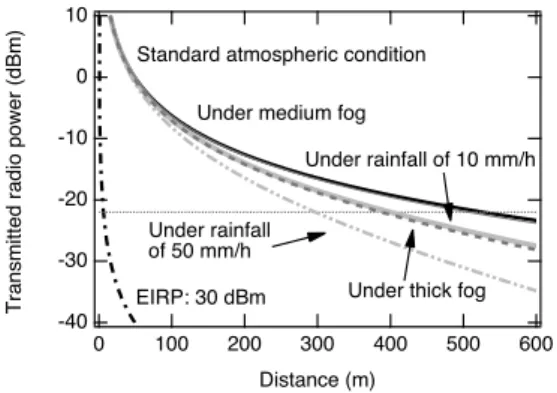
Figure 13 shows the estimated received power at the terahertz Rx in the terahertz band as a function of the trans- mission distance. Assuming an effective isotropic radio power (EIRP) of 30 dBm, which is realized by the terahertz signal power of−16 dBm and the antenna gain of 46 dBi, which are the conditions described in Sect. 3, the possible transmission distance will be less than 10 m. It should be noted that the signal power is estimated using the photocur- rent from the specification sheet of the PM, and the transmit- ted radio power at the input of the antenna is assumed to be
−22 dBm, corresponding to a photocurrent of approximately 2.5 mA when the observed BER is 2×10⁻³. The estimated distance agrees well with the results shown in 8. The trans- mission loss is estimated with the free-space path loss and atmospheric attenuation with a coefficient of 3 dB/km. On the contrary, the transmission distance would be extended to 500 m by an EIRP of 70 dBm. Such a high EIRP transceiver
Fig. 13 Evaluation of the possible transmission distance with an EIRP of 70 dBm. Black solid, gray solid, gray dashed, light-gray thick-solid, and light-gray two-dotted lines denote the estimated power under conditions of medium fog (0.05 g/m3), thick fog (0.5 g/m3), rainfall of 10 mm/h, and rain fall of 50 mm/h, respectively. The corresponding sensitivity and estimated radio power with an EIRP of 30 dBm are also shown as the dotted and black-dash-dotted lines, respectively, as a reference.
is realized by the implementation of a transmitter power am- plifier in the terahertz band. In these proof-of-concept ex- periments, there are no terahertz amplifiers installed in the Tx and Rx. For the power amplifier, semiconductor-based and vacuum-tube-based amplifiers are being developed with an output power of 10 mW and beyond 1 W in the terahertz band[46],[47]. Thus, this EIRP will be applicable to a real transceiver configuration.
For the EIRP of 70 dBm under medium- and thick-fog conditions, the possible transmission distance achieved is approximately 400 m. These medium- and thick-fog condi- tions have water vapor densities of 0.05 g/m3and 0.5 g/m3, and the resulting additional losses to atmospheric attenu- ation are approximately 0.7 dB/km and 8 dB/km, respec- tively; the estimated visibilities under these fog conditions are 300 m and 50 m[48]. The drastic change in the atmo- spheric attenuation of 7 dB cannot affect the possible trans- mission distance for a distance less than 1 km; thus, the dominant loss in the terahertz band could be caused by the free-space path loss.
Under rainy conditions, a large loss due to the rain- fall reduces the transmission distance in 300-GHz band rather than fog. Actually, in heavy shower (rainfall of 10 mm/h) and heavy rain (50 mm/h) conditions, the spe- cific attenuation coefficients are calculated to be 6.9 dB/km and 19.1 dB/km, respectively[49]. Even under heavy rain conditions, the possible distance achieved is approximately 300 m, which is comparable to the ISD of the current ur- ban microcell configuration described above. Therefore, the combination of a high-gain antenna and a high-power am- plifier is capable for the fronthaul and backhaul links using terahertz radio.
6. Conclusion
Terahertz signal transmission by advanced photonics tech- nology is demonstrated by the OFCG-based optical SHM.
The optical SHM/SHIQM are configured with structures similar to conventional modulators in microwave- and millimeter-wave communication. The SNR of the OFC sig- nal could be enhanced by the injection locking technique to increase the resulting SNR of the terahertz signal. DSP- aided coherent transmission and RToF-based radio signal delivery are demonstrated using optical SHMs. The esti- mated transmission distance will achieve 300 m, even un- der heavy rain conditions. The middle-range transmission capability is capable of application to high-speed mobile backhaul and fronthaul links. Terahertz communication will be key to the realization of future mobile networks with a throughput greater than 10-Gb/s.
Acknowledgments
The authors would like to thank Dr. Katsumi Fujii of the Ap- plied Electromagnetic Research Institute, National Institute of Information and Communications Technology, Japan, for aiding in the usage of a large-scale anechoic chamber. A.
nications Technology (NICT) for financial support through the R&D program, “Agile deployment capability of highly resilient optical and wireless seamless communication sys- tems” (2012–2015).
References
[1] P. Winzer, “Beyond 100G Ethernet,” IEEE Commun. Mag., vol.48, no.7, pp.26–30, 2010.
[2] Ed. M. Nakazawa, K. Kikuchi, and T. Miyazaki, High Spectral Density Optical Communication Technologies, pp.11–48, Springer, 2010.
[3] M. Birk, P. Gerard, R. Curto, L.E. Nelson, X. Zhou, P. Magill, T.J. Schmidt, C. Malouin, B. Zhang, E. Ibragimov, S. Khatana, M.
Glavanovic, R. Lofland, R. Marcoccia, R. Saunders, G. Nicholl, M. Nowell, and F. Forghieri, “Real-time single-carrier coherent 100 Gb/s PM-QPSK field trial,” IEEE J. Lightw. Technol., vol.29, no.4, pp.417–425, 2011.
[4] H. Shinohara, “Broadband access in Japan: rapidly growing FTTH market,” IEEE Commun. Mag., vol.43, no.9, pp.72–78, 2005.
[5] Rec. ITU-T G.984, “Gigabit-capable Passive Optical Networks,”
March 2008.
[6] Rec. ITU-R M.1457, “Detailed specifications of the terrestrial radio interfaces of International Mobile Telecommunications-2000 (IMT- 2000),” Feb. 2013.
[7] Rec. ITU-R M.2012, “Detailed specifications of the terrestrial radio interfaces of International Mobile Telecommunications Advanced (IMT-Advanced),” Feb. 2014.
[8] A. Osseiran, F. Boccardi, V. Braun, K. Kusume, P. Marsch, M.
Maternia, O. Queseth, M. Schellmann, H. Schotten, H. Taoka, H.
Tullberg, M.A. Uusitalo, B. Timus, and M. Fallgren, “Scenarios for 5G mobile and wireless communications: the vision of the METIS project,” IEEE Comm. Mag., vol.52, no.5, pp.26–35, 2014.
[9] J. Wells, “Faster than fiber: The future of multi-G/s wireless,” IEEE Microw. Mag., vol.10, no.3, pp.104–112, 2009.
[10] J.G. Andrews, S. Buzzi, W. Choi, S.V. Hanly, A. Lozano, A.C.
Soong, and J.C. Zhang, “What will 5G be?” IEEE J. Sel. Areas Commun., vol.32, no.6, pp.1065–1082, 2014.
[11] M. Davis and A. Makleff, “Innovations and new techniques for 4G mobile backhaul,” Mobile Backhaul Conf. at Int. Cell. Telecommun.
Internet Assoc. (CTIA) Wireless 2012, New Orleans, USA, May 2012.
[12] C. Jastrow, K. M¨unter, R. Piesiewicz, T. K¨urner, M. Koch, and T.
Kleine-Ostmann, “300 GHz Transmision System,” Electron. Lett., vol.44, pp.213–214, 2008.
[13] H.-J. Song and T. Nagatsuma, “Present and Future of Terahertz Communications,” IEEE Trans. Terahertz Sci. Tech., vol.1, no.1, pp.256–263, 2011.
[14] CPRI Specification V6.0, “Common Public Radio Interface (CPRI);
Interface Specification,” Aug. 30, 2013.
[15] European Telecommunications Standards Institute, “Open radio equipment interface (ORI); requirements for open radio equipment interface (ORI) (Release 4),” ETSI GS ORI 001 V4.1.1, Oct. 2014.
[16] Recommendation ITU-R P.676-5, “Attenuation of atmospheric gases,” 2001.
[17] H. Hoshina, T. Seta, T. Iwamoto, I. Hosako, C. Otani, and Y. Kasai,
“Precise measurement of pressure broadening parameters for water vapor with a terahertz time-domain spectrometer,” J. Quant. Spec- trosc. Radiat. Transfer, vol.109, no.12–13, pp.2303–2314, 2008.
for Mobile Communications Networks, Aetech House, 2002.
[20] A.J. Seeds and K.J. Williams, “Microwave Photonics,” IEEE J.
Lightw. Technol., vol.24, no.12, pp.4628–4641, 2006.
[21] J. Capmany and D. Novak, “Microwave photonics combines two worlds,” Nature Photonics, vol.1, no.6, pp.319–330, 2007.
[22] H.-J. Song, K. Ajito, A. Wakatsuki, Y. Muramoto, N. Kukutsu, Y. Kado, and T. Nagatsuma, “Terahertz Wireless Communication Link at 300 GHz,” IEEE Intl. Topic. Meeting Microw. Photon.
(MWP2010), WE3-2, Montreal, pp.42–45, Oct. 2010.
[23] A. Kanno, T. Kuri, I. Hosako, T. Kawanishi, Y. Yasumura, Y.
Yoshida, and K. Kitayama, “Optical and millimeter-wave radio seamless MIMO transmission based on radio over fiber technology,”
Optics Express, vol.20, no.28, pp.29395–29403, 2012.
[24] S. Koenig, D. Lopez-Diaz, J. Antes, F. Boes, R. Henneberger, A.
Leuther, A. Tessmann, R. Schmogrow, D. Hillerkuss, R. Palmer, T. Zwick, C. Koos, W. Freude, O. Ambacher, J. Leuthold, and I.
Kallfass, “Wireless sub-THz communication system with high data rate,” Nature Photonics, vol.7, no.12, pp.977–981, 2013.
[25] S. Horiguchi, K. Arakawa, Y. Minamikata, and T. Nagatsuma, “Er- ror-free 30–50 Gbps Wireless Transmission at 300 GHz,” in Proc.
2013 Asia-Pacific Microw. Conf., pp.660–662, 2013.
[26] A. Kanno, P.T. Dat, T. Kuri, I. Hosako, T. Kawanishi, Y. Yoshida, and K. Kitayana, “Waveform over fiber: DSP-aided coherent fiber- wireless transmission using millimeter and terahertz waves,” Proc.
SPIE, vol.9387, doi:10.1117/12.2077056, pp.1–11, 2015.
[27] A. Kanno, I. Morohashi, T. Kuri, I. Hosako, T. Kawanishi, Y.
Yasumura, Y. Yoshida, and K. Kitayama, “16-Gbaud QPSK Ra- dio Transmission Using Optical Frequency Comb with Recirculat- ing Frequency Shifter for 300-GHz RoF Signal,” IEEE Intl. Topic.
Meet. Microw. Photon., Noordwijk, Netherland, S7.6, pp.298–301, Sept. 2012.
[28] N. Sekine, A. Kanno, T. Kuri, I. Morohashi, A. Kasamatsu, I.
Hosako, T. Kawanishi, Y. Yoshida, and K. Kitayama, “30-Gbps- class terahertz transmission using optical sub-harmonic IQ mixer for backhaul/fronthaul directly connected to optical networks,” doc.:
IEEE 802.15-13-0653-00-0thz, Nov. 2013.
[29] T. Ishibashi and H. Ito, “Uni-traveling-carrier photodiodes,” Tech.
Dig. Ultrafast Electron. Optoelectronics, pp.83–87, Lake Tahoe, USA, 1997.
[30] H. Ito, T. Furuta, S. Kodama, and T. Ishibashi, “InP/InGaAs uni- travelling-carrier photodiode with 310 GHz bandwidth,” Electron.
Lett., vol.36, no.21, pp.1809–1810, 2000.
[31] T. Kawanish, T. Sakamoto, S. Shinada, and M. Izutsu, “Opti- cal frequency comb generator using optical fiber loops with sin- gle-sideband modulation,” IEICE Electron. Express, vol.1, no.8, pp.217–221, 2004.
[32] A. Kanno and T. Kawanishi, “Phase noise analysis of an optical fre- quency comb using single side-band suppressed carrier modulation in an amplified optical fiber loop,” IEICE Electron. Express, vol.9, no.18, pp.1473–1478, 2012.
[33] T. Kawanishi, T. Sakamoto, and M. Izutsu, “High-Speed Control of Lightwave Amplitude, Phase, and Frequency by Use of Electroop- tic Effect,” J. Sel. Top. Quantum Electron., vol.13, no.1, pp.79–91, 2007.
[34] T. Kuri, Y. Omiya, T. Kawanishi, S. Hara, and K. Kitayama, “Optical transmitter and receiver of 24-GHz ultra-wideband signal by direct photonic conversion techniques,” IEEE Intl. Topic. Meeting Microw.
Photon. (MWP2006), Grenoble, France, W3-3, pp.1–4, Oct. 2006.
[35] T. Schneider, M. Junker, and D. Hannover, “Generation of millime- tre-wave signals by stimulated Brillouin scattering for radio over fi- bre systems,” Electron. Lett., vol.40, no.23, pp.1500–1502, 2004.
[36] A. Kanno and T. Kawanishi, “Frequency-stabilized terahertz signal generation using an optical frequency comb and an injection-lock- ing technique,” Intl. Top. Meet. Microw. Photon., Sapporo, Japan, TuEC-2, pp.150–152, Oct. 2014.
[37] A. Kanno, T. Kuri, I. Morohashi, I. Hosako, T. Kawanishi, Y.
Yoshida, and K. Kitayama, “20-Gbaud QPSK Coherent Radio Transmission at 325 GHz with High-Gain Antennas,” 39th Intl.
Conf. Infrared Milli. Terahz. Waves, Arizona, USA, M3/B-3.6, pp.1–2, Sept. 2014.
[38] Rec. ITU-T G.975.1, “Forward Error Correction for High Bit Rate DWDM Submarine Systems,” Feb. 2004.
[39] K. Tsukamoto, T. Higashino, and S. Komaki, “Software definable radio networks for the ubiquitous networks,” XXXIIIth GA of URSI, vol.1, pp.205–208, New Dehli, India, Oct. 2005.
[40] J. Bartelt and G. Fwttweis, “Radio-Over-Radio: I/Q-Stream Back- hauling for Cloud-Based Networks via Millimeter Wave Links,”
IEEE GLOBECOM Wkshps on First Intl. Workshop on Cloud-Pro- cessing in Heterogeneous Mobile Commun. Netw., Atlanta, USA, pp.772–777, Dec. 2013.
[41] P.T. Dat, A. Kanno, K. Inagaki, and T. Kawanishi, “High-capac- ity wireless backhaul network using seamless convergence of ra- dio-over-fiber and 90-GHz millimeter-wave,” J. Lightw. Technol., vol.32, no.20, pp.3910–3923, 2014.
[42] A. Kanno, P.T. Dat, I. Hosako, T. Kawanishi, and H. Ogawa, “Ra- dio-on-terahertz over fiber system for future mobile fronthauling,”
in Proc. Globecom 2014 – Symp. Sel. Area Commun. Access Netw.
Sys., pp.2218–2222, 2014.
[43] T.D. Pham, A. Kanno, and T. Kawanishi, “High-speed and low-la- tency fronthaul system for heterogeneous wireless networks using seamless fiber–millimeter-wave,” IEEE Intl. Conf. Commun., Lon- don, UK, SAC07-ANS-02, pp.994–999, June 2015.
[44] 3GPP TS36.104 V10.9.0 Releasee 10, “LTE; Evolved Universal Ter- restrial Radio Access (E-UTRA); Base Station (BS) radio transmis- sion and reception,” Feb. 2013.
[45] ITU-R Rep. M.2135-1, “Guidelines for evaluation of radio interface technologies for IMT-Advanced,” Aug. 2009.
[46] D. Pukala, L. Samoska, T. Gaier, A. Fung, X.B. Mei, W. Yoshida, J. Lee, J. Uyeda, P.H. Liu, W.R. Deal, V. Radisic, and R. Lai, “Sub- millimeter-Wave InP MMIC Amplifiers From 300–345 GHz,” IEEE Microw. Wireless Components Lett., vol.18, no.1, pp.61–63, 2008.
[47] J.C. Tucek, M.A. Basten, D.A. Gallagher, and K.E. Kreischer, “220 GHz power amplifier development at Northrop Grumman,” in Proc.
IEEE Intl. Vacuum Electron. Conf., pp.553–554, 2012.
[48] Rec. ITU-R P.840-6, “Attenuation due to clouds and fog,” Sept.
2013.
[49] Rec. ITU-R P.838-3, “Specific attenuation model for rain for use in prediction methods,” March 2005.
Atsushi Kanno received B.S., M.S., and Ph.D. degree in science from the University of Tsukuba, Japan, in 1999, 2001, and 2005, re- spectively. In 2005, he was with the Venture Business Laboratory of the Institute of Science and Engineering, University of Tsukuba, where he was engaged in research on electron spin dy- namics in semiconductor quantum dot structures using the optical-polarization-sensitive Kerr ef- fect measurement technique. In 2006, he joined the National Institute of Information and Com- munications Technology Japan. From 2006 to 2007, he was also the mem- ber of the CREST-JST project entitled “Creation of Novel Functional De- vices Using Nanoscale Spatial Structures of the Radiation Field.” He is working on microwave/millimeter-wave/terahertz photonics, ultrafast op- tical communication systems, lithium niobate optical modulators, and the study of ultrafast phenomena in semiconductor optical devices. He is a member of the Institute of Electronics, Information and Communication Engineers (IEICE), the Japan Society of Applied Physics (JSAP), and the Institute of Electrical and Electronic Engineers (IEEE).
Pham Tien Dat received the B.Eng. (Hons.) degree in electronics and telecommunication engineering from Posts and Telecommunica- tions Institute of Technology, Vietnam, in 2003, and the M.Sc. and Ph.D. degrees in science of global information and telecommunication stud- ies from Waseda University, Japan, in 2008 and 2011, respectively. He worked as a Researcher at Research Institute of Posts and Telecommu- nications, Vietnam from 2003 to 2006. In 2011, he joined the National Institute of Information and Communications Technology, Japan. His research interests are in the field of microwave/millimeter-wave photonics, radio over fiber and opti- cal wireless systems. Dr. Pham is a member the Institute of Electrical and Electronic Engineers (IEEE).
Norihiko Sekine received the B.S., M.S., and Ph.D. degrees in electronic engineering from the University of Tokyo, Tokyo, Japan, in 1994, 1996, and 1999, respectively. After expe- rience in industry, he joined the National Insti- tute of Information and Communications Tech- nology (NICT), Tokyo. He is currently a Re- search Manager with NICT and his research in- terests include the physical properties of semi- conductor nanostructures in the terahertz regime and their application to terahertz devices and systems. Dr. Sekine is a member of the IEEE Photonics Society (IPS), the Institute of Electronics, Information and Communication Engineering (IEICE) of Japan, and the Japanese Society of Applied Physics (JSAP).
NICT). He is currently Associate Director Gen- eral of Advanced ICT Research Institute at the National Institute of Information and Commu- nications Technology (NICT), Tokyo. His re- search during 1995–1998 focused on cryogenic readout circuits with emphasis on ultralow 1/f-noise transistors for a far- infrared detector system. His research interests include nearly all aspects of terahertz-device technologies such as semiconductor emitters, detectors, and optical thin films. He is serving on several research committees for terahertz technologies.
Tetsuya Kawanishi received the B.E., M.E., and Ph.D. degrees in electronics from Kyoto University, Kyoto, Japan, in 1992, 1994, and 1997, respectively. From 1994 to 1995, he was with the Production Engineering Labora- tory, Matsushita Electric Industrial (Panasonic) Company, Ltd. In 1997, he was with Ven- ture Business Laboratory of Kyoto University, where he was engaged in research on electro- magnetic scattering and on near-field op- tics.
He joined the Communications Research Lab- oratory, Ministry of Posts and Telecommunications (now the National In- stitute of Information and Communications Technology, NICT), Koganei, Tokyo, Japan, in 1998. In 2004, he was a Visiting Scholar with the Depart- ment of Electrical and Computer Engineering, University of California, San Diego, USA. In 2015, he joined Waseda University as a Professor of De- partment of Electronic and Physical Systems, and is working on high-speed optical modulators and on RF photonics. Dr. Kawanishi received the URSI Young Scientists Award in 1999, an award for young scientists in the field of science and technology in 2006, from ministry of Education, Culture, Sports, Science, and Technology, Japan. He is a Fellow of the Institute of Electrical and Electronic Engineers (IEEE).
Yuki Yoshida received the B. E., M.
Inf., and Ph.D. degrees from Kyoto University, Kyoto, Japan, 2004, 2006, and 2009, respec- tively. Since 2009, he has been an assistant professor in the Department of Electrical, Elec- tronic and Information Engineering, Graduate School of Engineering, Osaka University. His research interests include digital signal process- ing for communications systems.
spent a year as a Research Fellow at the Uni- versity of California, Berkeley. In 1995, he joined the Communications Research Labora- tory (Presently, National Institute of Informa- tion and Communications Technology, NICT), Tokyo. Since 1999, he has been the Professor of the Department of Elec- trical, Electronic and Information Engineering, Graduate School of Engi- neering, Osaka University. His research interests are in photonic networks, optical signal processings, optical code division multiple access (OCDMA) systems, and radio-over-fiber systems. He has published over 240 papers in refereed journals and holds more than 30 patents.