EVALUATION OF STABILITY AND ITS COUNTERMEASURES OF UNDERGROUND LONGWALL COAL MINE UNDER SHALLOW AND WEAK GEOLOGICAL CONDITIONS IN INDONESIA
ピシット, マオ
http://hdl.handle.net/2324/4110474
出版情報:九州大学, 2020, 博士(工学), 課程博士 バージョン:
権利関係:
EVALUATION OF STABILITY AND ITS COUNTERMEASURES OF UNDERGROUND LONGWALL COAL MINE UNDER SHALLOW AND WEAK GEOLOGICAL CONDITIONS IN
INDONESIA
June 2020
DEPARTMENT OF EARTH RESOURCES ENGINEERING GRADUATE SCHOOL OF ENGINEERING
KYUSHU UNIVERSITY PISITH MAO
EVALUATION OF STABILITY AND ITS COUNTERMEASURES OF UNDERGROUND LONGWALL COAL MINE UNDER SHALLOW AND WEAK GEOLOGICAL CONDITIONS IN
INDONESIA
A DOCTORAL DISSERTATION
SUBMITTED TO THE GRADUATE SCHOOL OF ENGINEERING KYUSHU UNIVERSITY
AS A PARTIAL FULFILLMENT OF THE REQUIREMENTS FOR THE DEGREE OF
DOCTOR OF PHILOSOPHY OF ENGINEERING BY
PISITH MAO
SUPERVISED BY
ASSOC. PROF. TAKASHI SASAOKA CO-SUPERVISED BY
PROF. HIDEKI SHIMADA
DEPARTMENT OF EARTH RESOURCES ENGINEERING KYUSHU UNIVERSITY
FUKUOKA, JAPAN JUNE 2020
I
ABSTRACT
The combination of an increase in demand for coal and limitation of coal reserves that are suitable for surface mining had led Indonesian coal industry to begin adopting underground coal mining methods for extending their coal production. A new challenge had arisen since coal resources in this region are usually found in weak geological conditions. Due to the lack of experiences in underground mining and improper guidelines for the development of underground longwall mining in this country, many accidents related to ground control has been encountered during their underground mine operation. There are not enough researches focused on the development of longwall mining under weak geological conditions. Therefore, the purpose of this research is mainly to investigate ground behavior in underground longwall mine development under weak geological conditions. Plentiful numerical simulation models have been constructed and validated according to the actual field data to discuss and predict ground behavior during longwall development and extraction with numerous affective aspects such as initial stress condition, depth of the mine, support selections criteria, etc. This dissertation composed of five chapters. The main contents from each chapter can be summarized as the following:
Chapter 1: This chapter introduces the background and geotechnical issues that commonly occurred in the underground coal mines in Indonesia. The reviews of the literature on longwall mining technology and aspects that affect its stability with a few histories obtained from the past longwall mining works are also presented in this chapter. This chapter includes an outline and objectives of this dissertation.
Chapter 2: Stability of gate-entry is one of the first considerations for the development of longwall panel. Since there are two major factors influencing the stability of gate-entry in two different stages which are the longwall panel development and its extraction, an adequate support system has to be applied in order to maintain the gate-entry for both stages. This chapter discusses on the stability and appropriate design of gate road support for the longwall trial panel located between 100m and 150m depth by means of numerical simulation. Moreover, as a claystone laid on and coal seam is very weak and weaker than coal seam, the effect of remaining coal at the top and bottom of gate roads is also examined in order to increase the stability of the gate road. Based on a series of numerical simulations, the coal seam remained in the roof and floor of
II
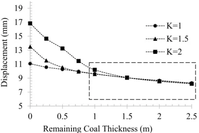
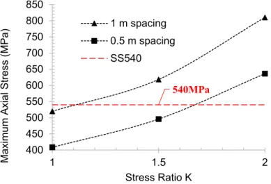
the gate road helps to increase the stability of the gate road and the optimum thickness of remaining coal seems to be at least 1m both on the roof and floor of it. During gate road development, the gate road can be maintained by the application of steel arch (SS540) with 1.1m spacing when the stress ratio is lower than 1.5. However, when the stress ratio is higher than 1.5, the spacing of steel arch has to be changed from 1m to 0.5m or additional support has to be installed. During the panel extraction, as the coal seam with 3m height is extracted, the stress is redistributed into the surrounding area and the high-stress concentration can be observed at the end of the gate road near the longwall face. Especially, the distance from the longwall face is less than 10m, the stress affected on the support becomes to be larger than the capacity of it. Hence, the additional support such as cribs and/or props have to be installed in the gate road according to the face advancing. Besides, the shape of cross section of gate road has also an obvious impact on the stability of it and a semi-circle shape is recommended in case that the depth of longwall panel is larger than 200m depth and/or weak geological conditions.
Chapter 3: This chapter discusses the stability and appropriate support design of gate road in the main production panels. There are two major key aspects influence the stability of gate road in the main panel including the effects of adjacent panels and multi seams extractions. As a result of a series of numerical simulations in the case of adjacent panels, the width of chain pillar should be larger than 50m in order to minimize the effect of adjacent panel extraction and maintain the stability of the gate road. The mining depth and the stress ratio have obvious impacts on the stability of gate road. In the case that the depth is 100m and/or 200m with the stress ratio is less than 1.5, the gate road can be maintained with 1.0m spacing. Besides, in the case that the depth is 200m with the stress ratio is less than 2.0 and/or the depth is 300m with the stress ratio is less than 1.5, the gate road can be maintained with 0.5m spacing. The depth is 300m and the stress ratio is larger than 1.5, the additional supports such as the rock bolts have to be installed. Moreover, the floor heave becomes to be more severe with increasing the depth and the counter measures such as dinting and/or installation of wooden bolt (dowel) has to be applied. For example, in the case of 300m depth, the 11 bolts have to be installed in the floor in order to maintain the stability of gate road. In order to understand the seam interaction on the stability of gate road in multi-seam mining, another series of numerical simulations had been carried out. It can be found that the
III
upper seam extraction has an obvious impact on the stability of gate road in the lower panel when the interburden is less than 50m. Besides, the effect increases with decreasing the thickness of the interburden. In the case that the lower panel (the second extraction panel) is located at 200m depth and the distance between the upper panel (the first extraction panel) and the lower one is less than 50m, the spacing of steel arch has to be changed from 1.0m to 0.5m. Considering the other aspect of mine design such as mineable coal seam, coal grade, seam depth, etc., if the thin interburden cannot be avoidable, stronger support is required.
Chapter 4: This chapter discusses the stability and control measures of longwall face under weak geological conditions. The stability of longwall face is very crucial during panel extraction as it allows the cutting operation to work smoothly and safely. One of the most important factors for the stability of longwall face is the control and the selection of shield support. There are several criteria for the selection of appropriate shield support apart from shield support capacity. These criteria include in- situ stress condition, canopy ratio, leg pressure. A series of numerical simulations had been constructed in order to discuss the influence of these parameters on the stability of longwall face. It can be seen that the fracture zone is formed around the canopy tip and the stability of longwall face decreases with decreasing the stress ratio. Moreover, the fracture zone becomes even more severe after the cutting web. As the competent of the claystone increases with the increasing of the depth, the same shield configuration seems to perform better in the deeper depth which results in less fracture zone. It can be also found that the roof caving behavior is different with different stress ratio. The roof caving behavior in the longwall face can be divided into two types based on the condition of stress ratio. When the stress ratio is lower than 1, a roof caving behavior follows the detached block model. On the other hand, when the stress ratio is larger 1, a roof caving behavior follows the bulking model. Canopy ratio of 2 is the preferred for reducing the fracture zone on the roof, especially for the shallower depth where the rock is relatively weak. Based on the relationship between the leg pressure and fracture zone, it can be said that the setting pressure at the beginning of the loading cycle should be set as low as 6,000kN. The ratio of shield convergence before and after web varies depending on the depth. The higher convergence ratio can be seen in the shallower depth. In order to decrease the shield convergence and increase the stability of the shield, both the distance between longwall face and canopy and the cutting width should be
IV
reduced. In the case that the stress ratio is 1 or above, the fracture zone around the longwall face reduces to the allowable range even after web. However, in case that the stress ratio is 0.5, the risk of roof fall and/or collapse of longwall face is very high. So, in this case, the installation of dowel to the longwall face has to be conducted in order to improve the stability of longwall face and the roof. The selection criteria included canopy ratio of 2, setting pressure at least 6,000kN with the total yield pressure at least 10,000kN, set-to-yield convergence at least 60mm as well as the shield configuration that allow 0.25m of face to tip of the canopy with the cutting web width of 0.5m.
Chapter 5: This chapter summarizes and concludes the key results and findings of the research.
V
ACKNOWLEDGMENTS
I would like to express my deepest gratitude to my supervisor Associate Prof.
Takashi Sasaoka of Department of Earth Resources Engineering, Kyushu University, for your valuable guidance, kind support, and encouragement throughout my research work in Japan. I really appreciate your patience, dedication, effort, countless constructive discussions, and valuable advice which make this research successful.
My sincere gratitude and appreciation also extend to my co-supervisor Prof. Hideki Shimada of the Department of Earth Resources Engineering for his valuable suggestions and guidance during my stay in Japan. I greatly respect your kindness. My sincere thank also goes to the member of my examination committee Prof. Yasuhiro Mitani of Department of Civil and Structural Engineering, Kyushu University, who gave many valuable and constructive suggestions during the development of this thesis.
I would like to deeply thank Assistant Prof. Akihiro Hamanaka of Department of Earth Resources Engineering, Kyushu University, Assistant Prof. Sugeng Wahyudi of Department of Earth Resources Engineering, Kyushu University for their countless suggestions and kind assistance during the developments of this research as well as during my daily life in Japan. I am also grateful for all the members of the Rock Engineering and Mining Machinery Laboratory, Department of Earth Resources Engineering of Kyushu University, especially Dr. Phanthoudeth Pongpanya and Dr.
Naung Naung for supporting me to conduct the research as well as making my daily life in Japan wonderful.
I also would like to acknowledge AUN-SEED/Net (JICA) for fully sponsoring financial support for my study in Japan and taking care of my well-being during my time in Japan.
This research is also made possible with the kind help from PT Gerbang Daya Mandiri (GDM) who provides valuable field data that are necessary for this research.
Last but not least, I would like to send my special thanks to my family who always love, support, and encourage me to overcome my hard time. I also would not forget to acknowledge my close friends who spend a lot of time with me in Japan which make my life here wonderful and enjoyable.
VI
TABLE OF CONTENTS
ABSTRACT. ... I ACKNOWLEDGMENTS ... V TABLE OF CONTENTS ... VI LIST OF FIGURES ... IX LIST OF TABLES ... XIV
CHAPTER 1 INTRODUCTION ... 1
1.1. Background ... 1
1.2. Study Area ... 2
1.3. Coal Mining Methods... 5
1.4. Literature Review ... 7
1.4.1. Gate stability ... 8
1.4.2. Face Stability ... 11
1.4.2.1. Longwall Face Support System. ... 11
1.4.2.2. Roof Caving Theory ... 13
1.4.3. Seam Interaction in Multiple Seam Longwall Mining ... 18
1.5. Problem Statements and Motivations ... 20
1.6. Research Objectives ... 21
1.7. Research outline ... 22
References ... 23
CHAPTER 2 GATE-ENTRY STABILITY OF TRIAL PANEL ... 27
2.1. Background ... 27
2.2. Modelling ... 30
2.2.1. General Model Description ... 30
2.2.2. Goaf Modelling ... 33
2.2.3. Model Validation ... 35
2.3. Results and Discussions ... 37
2.3.1. Stability of Gate-entry under the Influence of RCT ... 37
2.3.2. Gate-entry Stability during Gate Development ... 39
2.3.3. Gate-entry Stability during Panel Extraction ... 40
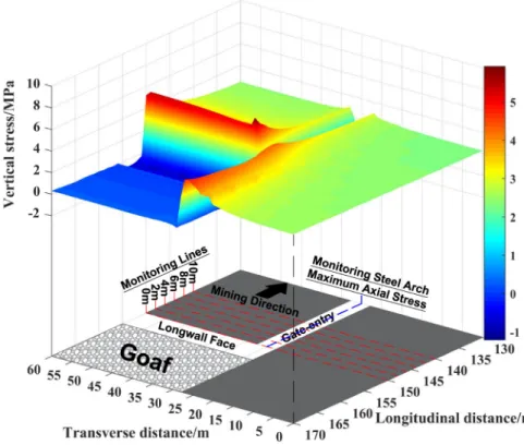
2.3.3.1. Vertical Stress Distribution ... 41
2.3.3.2. Maximum Axial Stress of Individual Supports Along Gate-entry . 44 2.3.4. Influence of Gate-entry Cross-sectional Shape on Its Stability ... 45
VII
2.4. Conclusions ... 47
References ... 48
CHAPTER 3 GATE-ENTRY STABILITY OF MAIN PANEL ... 51
3.1. Introduction ... 51
3.2. Safety Factor Calculation from Mohr-Coulomb Failure Criterion with a Tension Cut-Off ... 53
3.2.1. Model Description ... 54
3.3. Results and Discussions ... 57
3.3.1. Panel Interaction on Gate-entry ... 57
3.3.1.1. Study of Chain Pillar Size ... 57
3.3.1.2. Appropriate Support for Main Panel Gate-entry ... 60
3.3.2. Seam Interaction on Gate-entry ... 62
3.3.2.1. Study of Interburden Thickness ... 62
3.3.2.2. Appropriate Support for Main Panel Gate-entry in Multiple Seam Longwall Mining ... 65
3.4. Conclusions ... 72
References ... 74
CHAPTER 4 STABILITY AND CONTROL MEASURES OF STABILITY OF LONGWALL FACE ... 75
4.1. Background ... 75
4.2. Modelling ... 77
4.2.1. General Model Description ... 77
4.2.2. Modelling for Powered Shield Support ... 81
4.2.3. Description of Research Cases Study ... 82
4.3. Results and Discussions ... 84
4.3.1. Effect of Stress Ratio on Stability of Longwall Face ... 86
4.3.1.1. Failure Zone Surrounding the Longwall Face ... 86
4.3.1.2. Shield Convergence ... 89
4.3.2. Effect of Shield Support Canopy Ratio on Stability of Longwall Face . 90 4.3.2.1. Failure Zone Surrounding the Longwall Face ... 90
4.3.2.2. Shield Convergence ... 92
4.3.3. Effect of Shield Leg Pressure on Stability of Longwall Face ... 93
4.3.3.1. Failure Zone Surrounding the Longwall Face ... 93
4.3.3.2. Shield Convergence ... 95
4.3.4. Countermeasure for Improving Stability of the Longwall Face ... 96
VIII
4.4. Conclusions ... 98 References ... 100 CHAPTER 5 CONCLUSIONS ... 102
IX
LIST OF FIGURES
Figure 1.1. Annual coal production and utilization ... 1
Figure 1.2. Location map of GDM ... 2
Figure 1.3. Underground mine layout ... 3
Figure 1.4. General Stratigraphy column of the study area ... 4
Figure 1.5. Coal measure strength comparison (Pongpanya, Sasaoka, Shimada, Hamanaka, et al., 2017) ... 4
Figure 1.6. Correlation between claystone strength and depth ... 5
Figure 1.7. General room and pillar method schematic (Brady and Brown, 2007b) .... 5
Figure 1.8. 3D schematic of longwall mining method ... 7
Figure 1.9. Typical longwall configuration ... 7
Figure 1.10. Vertical stress distribution surrounding longwall (Whittaker and Potts, 1974) ... 8
Figure 1.11. Preferred gate shape for different roof type: (a) weak roof (b) strong roof (Thomas, 1978) ... 9
Figure 1.12. Bolt support (a) schematic (b) field application (Brady and Brown, 2007a) ... 9
Figure 1.13. Steel arch gate support (a) schematic (b) field application (Toraño et al., 2002) ... 10
Figure 1.14. Chronology of longwall shield powered support (Galvin, 2016) ... 11
Figure 1.15. Schematic of semi-mechanized face support system (Sasaoka et al., 2015) ... 12
Figure 1.16. Comparison between two-leg and four-leg of shield power support design ... 13
Figure 1.17. Detached model geometries for shield with four-leg design (Galvin, 2016) ... 14
Figure 1.18. Interaction between shield support and the immediate roof and floor (Barczak, 2017) ... 15
Figure 1.19. Immediate roof strata under the effect of beam composite (Barczak, 2017) ... 15
X
Figure 1.20. Loading behavior of longwall shield support (a) bulking model (b) detached block model (c) periodic weighting model (d) unconfined model (Galvin,
2016) ... 16
Figure 1.21. Typical shied loading cycle in longwall mining ... 17
Figure 1.22. Rock-support interaction analysis for longwall face. (Everett and Medhurst, 2003) ... 17
Figure 1.23. Type of multiple seam sequence (a) overmining (b) undermining (Ghabraie, 2016) ... 18
Figure 1.24. Relationship between sandstone percentage and interburden thickness (Haycocks et al., 1982) ... 19
Figure 2.1. Stress distribution during longwall panel extraction ... 27
Figure 2.2. Mine layout of GDM in early stage. ... 28
Figure 2.3. General stratigraphy surrounding trial panel region ... 29
Figure 2.4. Layout of trial panel ... 29
Figure 2.5. Model Dimensions ... 31
Figure 2.6. Modelling of steel arch for roof support ... 31
Figure 2.7. Study Case of Remaining Coal Thickness ... 32
Figure 2.8. Goaf modelling during panel extraction ... 34
Figure 2.9. Location map of displacement monitoring devices (TT 39 and EX53) ... 35
Figure 2.10. Comparison between telltale results and simulation result (TT39) ... 36
Figure 2.11. Comparison between extensometer results and simulation result (EX53) ... 36
Figure 2.12. Monitoring points of displacement results. ... 37
Figure 2.13. Relationship between gate-entry displacement and RCT on the roof .... 38
Figure 2.14. Relationship between gate-entry displacement and RCT on the floor ... 39
Figure 2.15. Maximum axial stress on steel arch for 100m in depth (1m spacing) .... 40
Figure 2.16. Maximum axial stress on steel arch for 150m in depth ... 40
Figure 2.17. 3D schematic of vertical stress above the mining panel in 100m in depth ... 42
Figure 2.18. 3D schematic of vertical stress above the mining panel in 150m in depth ... 42
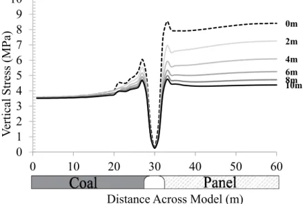
Figure 2.19. Vertical stress with different distance from the longwall face for 100m in depth ... 43
XI
Figure 2.20. Vertical stress with different distance from the longwall face for 150m in
depth ... 43
Figure 2.21. Maximum axial stress of steel support along gate-entry for 100m in depth ... 45
Figure 2.22. Maximum axial stress of steel support along gate-entry for 150m in depth ... 45
Figure 2.23. Cross-sectional shape of gate-entry (A: Flat horseshoe, B: Semi-circle) ... 46
Figure 2.24. Roof displacement results comparison ... 46
Figure 2.25. Maximum support axial stress results comparision ... 47
Figure 3.1. Mine layout of GDM. ... 51
Figure 3.2. General stratigraphy column of the study area ... 52
Figure 3.3. Factor of safety by Mohr-Coulomb failure envelope ... 53
Figure 3.4. Mohr-Coulomb with tension cut-off ... 54
Figure 3.5. Model geometries for panel interaction ... 55
Figure 3.6. Longwall section simulated for the model ... 55
Figure 3.7. General model dimensions ... 56
Figure 3.8. Vertical stress during gate-entry development ... 58
Figure 3.9. Vertical stress during panel extraction with 20m chain pillar size ... 58
Figure 3.10. Vertical stress during panel extraction with 50m chain pillar size ... 59
Figure 3.11. Vertical stress comparison between difference size of chain pillar ... 59
Figure 3.12. Maximum axial stress on steel arch along unmined panel gate-entry .... 60
Figure 3.13. Support axial stress increment percentage before and after panel extraction ... 61
Figure 3.14. Safety factor of gate-entry support under the influence of panel interaction ... 62
Figure 3.15. Failure zone of gate-entry with various interburden (150m in depth) .... 63
Figure 3.16. Failure zone of gate-entry with various interburden (200m in depth) .... 64
Figure 3.17. Failure zone of gate-entry with various interburden (300m in depth) .... 65
Figure 3.18. Support system configuration ... 66
Figure 3.19. Factor of safety contour for 1m spacing support (150m in depth) ... 66
Figure 3.20. Factor of safety contour for 0.5m spacing support (150m in depth) ... 67
Figure 3.21. Factor of safety contour for 1m spacing support (200m in depth) ... 68
XII
Figure 3.22. Factor of safety contour for 0.5m spacing support (200m in depth) ... 68
Figure 3.23. Factor of safety contour for 1m spacing support (300m in depth) ... 69
Figure 3.24. Factor of safety contour for 0.5m spacing support (300m in depth) ... 69
Figure 3.25. Safety factor of the gate roof with difference depth ... 70
Figure 3.26. Safety factor of the gate floor with difference depth ... 71
Figure 4.1. Operation in Longwall Face ... 75
Figure 4.2. Shield Selection based on detached roof model ... 76
Figure 4.3. Leg position determined by canopy ratio ... 77
Figure 4.4. General Dimension of the model ... 78
Figure 4.5. Longwall Configurations and Densified Zone ... 78
Figure 4.6. Final state of the model after analysis ... 80
Figure 4.7. The detail cross-section of the longwall face. ... 80
Figure 4.8. Interaction between shield support and surrounding rock ... 81
Figure 4.9. Cross-section of longwall machineries (a) before web (b) after web (x: face- to-tip distance, y: cutting width) ... 82
Figure 4.10. Modelling of shield support using in the model ... 82
Figure 4.11. Applied stress boundary distribution of each canopy ratio. ... 83
Figure 4.12. Failure zone result surrounding the longwall face. ... 85
Figure 4.13. Shield vertical displacement result ... 85
Figure 4.14. Failure zone developed in the longwall face under the influence of stress ratios (before web) ... 87
Figure 4.15. Failure zone developed in the longwall face under the influence of stress ratio (after web) ... 88
Figure 4.16. Shield convergence under the influence of stress ratio. ... 90
Figure 4.17. Failure zone developed in the longwall face under difference canopy ratios (before web) ... 91
Figure 4.18. Failure zone developed in the longwall face under difference canopy ratios (after web) ... 92
Figure 4.19. Shield convergence under different canopy ratios of shield support. ... 93
Figure 4.20. Failure zone developed in the longwall face under different leg pressures. ... 94
Figure 4.21. Failure zone developed in the longwall face under difference leg pressure capacities ... 95
XIII
Figure 4.22. Shield Convergence under difference leg pressure. ... 96 Figure 4.23. Failure zone in longwall face utilizing countermeasure (before web) ... 97 Figure 4.24. Failure zone in the longwall face utilizing countermeasure (after web) 98
XIV
LIST OF TABLES
Table 2.1 Rock mechanical properties ... 32
Table 2.2. Roof support mechanical properties ... 33
Table 2.3. Lithology coefficients ... 35
Table 2.4. Gate roof geology boring. ... 36
Table 3.1. Mechanical properties of rocks ... 56
Table 3.2. Mechanical properties of steel arch support ... 57
Table 3.3. Mechanical properties of cable bolt ... 57
Table 4.1. Summary of rock properties using in the simulation ... 79
Table 4.2. Summary of steel arch properties using in the simulation ... 79
Table 4.3. Apply boundary stress converting from legs pressure ... 83
1
CHAPTER 1 INTRODUCTION 1.1.Background
Indonesia is known for its abundant coal resource which leads this country to become one of the biggest coal exports in the world. The total production of coal is increasing annually as shown in Figure 1.1 (Agus et al., 2019; Djoko et al., 2019). The domestic utilization of coal is also increasing significantly. For Indonesia, coal is utilized for power plants, smelters, steel factories, etc. The energy mix of Indonesia for coal is projected to increase by 10% of the country's total energy mix from 2011 to 2025 (Djoko et al., 2019). This increment of coal consumption motivated the coal mining industries to increase their production to keep up with the coal demand. For some mining company, when coal reserve is exhausted for surface mining due to high stripping ratio, it is not always easy to develop the new surface mines in other location.
The facing difficulties can cause by the licensing process, location of the coal resources such as protected area, urban structure or agriculture where surface mining is not suitable or prohibited for coal mining. Through the combination of an increase in demand for coal and limited coal reserves that suitable for surface mining, directed Indonesian coal industrial begin adopting underground coal mining methods for extending their coal production.
Figure 1.1. Annual coal production and utilization
2% 2% 2% 7% 6%
13%
6% 7%
19%
31%
0%
10%
20%
30%
40%
50%
60%
70%
80%
90%
100%
0 100 200 300 400 500 600 700
2010 2011 2012 2013 2014 2015 2016 2017 2018 2019
Coal (million tons)
Annual Data
Production Domestic Export Annual Increase of Domestic Use
2 1.2.Study Area
This research is conducted on PT Gerbang Daya Mandiri (GDM) coal mine which is situated in East Kalimantan Island, close to Samarinda city in the area called Kutai Kertanegara as shown in Figure 1.2. Based on the analysis of a series of drill-holes data, the geological structure of that area is monocline which contains many coal seams with the dip and thickness from 3˚ to 13˚ and from 0.15m to 9.80m, respectively. The estimated coal reserve for this mine is 58.3Mt with the recoverable coal reserve of 29.2Mt. According to the mine planning the annual production is around 1Mt which results in around 30 years of the estimated life of mine. This mine adopted an underground longwall mining method for coal extraction. The coal seam located in the agriculture area, the surface above the underground mining area contain mostly rice field and some houses community. Figure 1.3 illustrated the overall underground mine layout. Seam BC is the first target seam for the longwall mining operation. In the future, multiple seam longwall mining is also expected after finishing the first seam, according to the mine design. After finishing the operation of the first seam, the second deeper seam F is developed.
Figure 1.2. Location map of GDM
3
Figure 1.3. Underground mine layout
Figure 1.4 illustrates the stratigraphy column that represents the general rock formation in the research area. This column is associated with Pulau Balang formation and Balikpapan formation which is aged between middle to upper Miocene (Widodo et al., 2010). Coal seams are surrounded by weak rock mass. The coal measures of Indonesia is very weak compared to other countries. As shown in Figure 1.5, the highest coal measure in Indonesia is less than 25MPa which is considered weak or low strength rock. Specifically, coal measures in GDM mine and most of the coal resources in Kalimantan region have much lower strength around 5MPa to 15MPa. The dominant rock in this region is claystone.
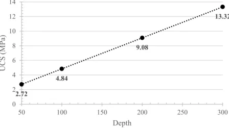
Laboratory tests on core samples indicated that the competence of the dominant rock is correlated with the depth. On average, higher strength of claystone can be observed in a deeper depth as shown in Figure 1.6. The average UCS strength of the coal is around 8.16 MPa.
4
Figure 1.4. General Stratigraphy column of the study area
Figure 1.5. Coal measure strength comparison (Pongpanya, Sasaoka, Shimada, Hamanaka, et al., 2017)
5
Figure 1.6. Correlation between claystone strength and depth 1.3. Coal Mining Methods
There are two common methods for underground coal extraction which include room and pillar mining method and longwall mining method. For room and pillar method, coal is produced from the multiple open entries or rooms in a regular grid arrangement. The remnants coal in between the room act as pillar to support the immediate roof which also controls the global ground response of the rock medium (Brady and Brown, 2007b). Figure 1.7 shows a general configuration of room and pillar mining operation. The immediate roof of the room can be either support artificially or unsupport based on properties of the roof itself. This method is suitable for flat-lying seam with dip up to 30ᵒ. The preferred geological condition for this method selection is with a strong rock medium with little discontinuity.
Figure 1.7. General room and pillar method schematic (Brady and Brown, 2007b)
2.72
4.84
9.08
13.32
0 2 4 6 8 10 12 14
50 100 150 200 250 300
UCS (MPa)
Depth
6
Longwall mining is considered one of the most common methods adopted for coal mining. 3D schematic of longwall is illustrated in Figure 1.8. According to Galvin (2016), longwall mining had been improved to become one of the safest underground mining methods with the highest production rate since a few decades ago. This method composted by a series of parallel panels separated by chain pillar. The most common longwall method is the retreat method. A typical longwall configuration schematic is illustrated in Figure 1.9. The development of retreat longwall mining starts from developing incline tunnels to the coal seam. Then a system of tunnel call main roadway system is developed. Gate-entries are developed from the main roadway to the end of the panel after which both gates are connected to create the cutting face. Then, the coal seam is extracted in the retreat direction back to the main roadway leaving a portion of coal as barrier pillar. Longwall face is supported by an array of shield support. The shield support legs can be extended or shrunk to accommodate the movement along the face retreat direction. For low strengths of the coal measures rock, failure zone can be induced surrounding the opening which required some structural support or strata control measure.
According to Brady and Brown (2007a) measure of longwall mining method divided into four main classifications which including the following:
• Longwall face stability control: to maintain a safe working condition and assure a smooth continuous panel retreat operation.
• Stability of main roadway and gate-entry: to provide access to the face for equipment and coal transportation as well as for ventilation.
• Stability of chain or rib pillar: to protect the gate-entry of unmined panel from the influence of goaf area from the mining panel.
• Backfilling at goaf area: to reduce the overall displacement in the goaf area which tends to reduce the total surface subsidence.
7
Figure 1.8. 3D schematic of longwall mining method
Figure 1.9. Typical longwall configuration 1.4.Literature Review
Many aspects require to take into consideration when developing longwall mining which including the characteristic of coal measure, surrounding rocks, initial stress conditions, longwall configurations, etc. In weak geological conditions, the effect of each aforementioned aspect can be enhanced to a severe degree due to a large portion of the coal seam is extracted. When coal panel is extracted, stress which usually keeps in balancing by the extracted portion of coal is redistributed into the nearby area. Figure 1.10 shows a general vertical stress distribution surrounding the longwall panel base on Whittaker and Potts (1974). According to this figure, during panel extraction vertical stress is released and decreased to the minimum value in mined zone which results a
Chain Pillar
8
rapid increase of stress concentration in the unmined zone in all horizontal directions.
The distance of peak stress into the unmined coal varies depending on mechanical properties of rock and local in-situ stresses (Brady and Brown, 2007a; Whittaker and Potts, 1974). Cross-sections of Y-Y and X2-X2 indicate that vertical stress in goaf area will increases when the longwall face is retreated away further and further. A few research categories have arisen when it comes to ground control in longwall coal mine.
Those are including the stability control of the gate, longwall face stability as well as seam interaction, in case where multiple seams are developed.
Figure 1.10. Vertical stress distribution surrounding longwall (Whittaker and Potts, 1974)
1.4.1. Gate stability
In longwall mine development, the stability of gate-entry is considered to be one of the most important components, especially during panel extraction. Gate-entry does not only serve as a way of material transportation but also an important component of the ventilation system to get rid of dust and harmful gases and to provide fresh air to longwall face (Brune and Sapko, 2012). Two major aspects influence the stability of gate-entry (Jiang et al., 2016). First is during the excavation operation of the gate-entry itself due to stress redistribution around the gate opening. Second is during longwall panel extraction which causes by the stress redistribution as described in the previous section.
9
Figure 1.11. Preferred gate shape for different roof type: (a) weak roof (b) strong roof (Thomas, 1978)
Figure 1.12. Bolt support (a) schematic (b) field application (Brady and Brown, 2007a)
10
Figure 1.13. Steel arch gate support (a) schematic (b) field application (Toraño et al., 2002)
The shape of longwall gate varies from rectangular or horseshoes to semi-circle shape depending on the design and site conditions as shown in Figure 1.11. The roof curvature of the gate tends to decrease the overall instability of the gate opening. As a result, horse-shoes or semi-circle usually adopted for weaker rock while rectangular shape gate widely adopted for hard coal seam (Hobbs, 1969). Bolt support is one of the most common support adoptions in longwall coal mine as it accompanies around 90%
of support used for the gate in the U.S. and Australia as well as 80% in China (Miao et al., 2017; Peng, 2015). However, most of the adoption field is located in the hard coal region. Figure 1.12 shows a typical schematic and field application of bolt. Although bolt is considered the standard gate support for longwall, lots of researches had proved insufficient of bolt support adoption in weak coalfield and suggest the adoption of steel arch for gate support instead (Hong-pu et al., 2009; Jiao et al., 2013; Meng et al., 2014;
Phanthoudeth, 2018; Pongpanya, Sasaoka, Shimada, Hamanaka, et al., 2017; Toraño et al., 2002). The application of steel arch support as get support is shown in Figure 1.13.
11 1.4.2. Face Stability
The stability of the longwall face is one of the fundamental considerations when it comes to designing a sustainable longwall mine (Peng, 2019). The face of the longwall is the region where the coal seam is extracted. Even advanced longwall system have been improved toward the automated system, it always required some miners to work in the longwall face in order to keep the face moving (retreating). The stability of the longwall face is fully maintained by the array set of power shield support.
1.4.2.1.Longwall Face Support System.
Although, longwall mining of coal history is dated back to the 1800s, the powered support which provides the basic longwall shield support is not introduced until the 1940s (Galvin, 2016). Since the introduction of powered shield support, the innovation of this support technology had been improved significantly contributed by many countries. The major development of this support took place in Germany where the simple hinge is replaced by lemniscate linkage. The chronology of longwall shield powered support is illustrated in Figure 1.14.
Figure 1.14. Chronology of longwall shield powered support (Galvin, 2016)
12
Currently, there are two commonly adopted support systems for longwall face including semi-mechanized system and fully-mechanized system. Figure 1.15 shows the schematic of semi-mechanized system for longwall face which is sometimes called prop and cap mining. This system consists of a few legs connecting to chocks to support the roof. This system required manual retreat or advance movement by the miner. A fully-mechanized system, on the other hand, utilizes high power shield for roof support.
The shield retreat or advancing movement can be operated automatically after the face is cut.
Figure 1.15. Schematic of semi-mechanized face support system (Sasaoka et al., 2015)
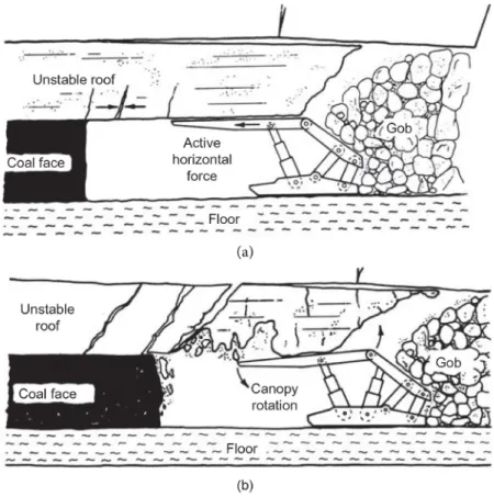
The latest major development of fully-mechanized high capacity two-leg shield support had innovated the landscape of longwall mining powered roof support as this design offers a much better strata interaction than the four-leg design with additional active horizontal force (Barczak, 2017). The comparison between these two designs is presented in Figure 1.16. In the four-leg design, the different directions of leg inclination can cause the cancelation of active horizontal force between each leg. This
13
force is induced to the immediate roof which is crucial for maintaining the stability of that roof from the compression state. Load distribution from two positions of the front and rear legs generates an unbalance distribution which sometimes results in rotation of the canopy. This phenomenon will reduce the contact between the canopy and immediate roof which enhances the fracture on the roof. For the same shield capacity, the front leg of the four-leg design also provides less support capacity in the front part of the canopy which results in more failure zone surround the tip area of the canopy.
The four-leg design is not suitable with weak roof which is prone to the cavity (Barczak, 2017).
Figure 1.16. Comparison between two-leg and four-leg of shield power support design
1.4.2.2.Roof Caving Theory
Barczak (2017) had pointed out that the conventional method of selection power shield support is based on the detached roof block model in Figure 1.17. It basically means that the shield has to be able to withstand the load generated from the detached block above in the immediate roof. This model assumes that the rigid shield is uniformly loaded by a dead weight of the detached block of the immediate roof. Figure
14
1.17 gives an example of detached model block for four-leg shield design. Many factor influence the geometry shape of the block which have differed position of gravity center of the block to fall into three positions such as the area before the front leg, the area behind the rear leg or in between both legs. Stabilizing force is needed to balance the total force. From this model, the maximum weight of the detached block W, can be identified by Equation 1.1, assuming that the rate of yield is equal for both front and rear legs.
𝑊𝑊 =𝐹𝐹 �𝑠𝑠−𝑤𝑤𝑠𝑠−𝑓𝑓� (1.1)
where,
F = normal component of the combined capacity of the front leg s, w, f, r = arm distance
Figure 1.17. Detached model geometries for shield with four-leg design (Galvin, 2016)
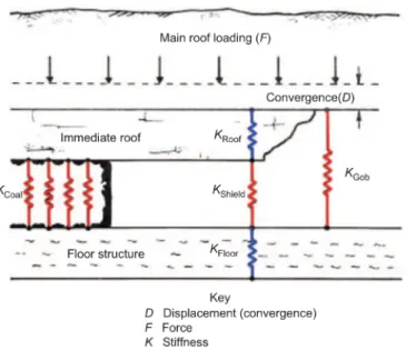
However, later publications argue that the previous model is ignored the roof convergence which is also present and has some impact on the powered shield support (Barczak, 1991). This leads to the inappropriate selection of shield support. The better model which integrates roof support interaction with the immediate roof and floor is shown in Figure 1.18. The equivalent stiffness of the total ground supporting system needs to be taking into consideration. There is a couple of factors affecting the behavior of shield loading (Barczak, 2017). First of all, although shield stiffness is fixed base on the adopted shield type, stiffness of immediate roof and floor can be change related to
15
shield resistance which can be increase or decrease shield loading through the mechanism of compacting, closing joints and strength hardening of the material.
Second is that, considering immediate roof which composes from beds strata as stack beams structure, the friction force between layer would increase by increasing the shield resistance. As shown in Figure 1.19, this phenomenon will increase the bending resistance of the laminated layer of the immediate roof.
Figure 1.18. Interaction between shield support and the immediate roof and floor (Barczak, 2017)
Figure 1.19. Immediate roof strata under the effect of beam composite (Barczak, 2017)
16
In practical, according to Galvin (2016) the load acting on shield support is quite complex and statically indetermination. Many factors influence the stiffness of the immediate roof and floor. These including mining depth, mining height, mechanical properties and thickness of the roof and floor, joints direction and dip, the configuration of shield support, etc. As a result, there is not a universal model that fits all types of mine conditions. It required further studies and monitors such as micro-seismic, leg pressure, convergence, surface subsidence, numerical modeling, as well as site observation. Figure 1.20 illustrated some basic models that commonly found in the wide study range of loading behavior of shield support.
Figure 1.20. Loading behavior of longwall shield support (a) bulking model (b) detached block model (c) periodic weighting model (d) unconfined model (Galvin,
2016)
According to Barczak (2017), a typical loading shield cycle in longwall mine begin with setting pressure and terminate in the end pressure. The total shield load is considered to be the combination of active and passive load on the shield. The initial setting pressure is actively set before the support interacts with the roof and floor. After the support-rock contact, a passive load behavior of the shield support is generated corresponding to the total convergence of the support. Figure 1.21 shows the monitored leg pressure profile of a typical loading cycle. In general, loading rates differ for each mining cycle in relation to shearer activity that influences the behavior of the roof. The
17
shear effect can be seen in CD section in Figure 1.21. Because the shield is typically lowered prior to the end of the shearer effect, this shearer effect still presents in the next new loading cycle in section AB.
Figure 1.21. Typical shied loading cycle in longwall mining
Figure 1.22. Rock-support interaction analysis for longwall face. (Everett and Medhurst, 2003)
In principle, setting pressure can also have an influence on the convergence rate of the roof. As state in one study of Everett and Medhurst (2003) on the ground respond
18
curve of the shield support in Australia, which show a reduction of convergence of roof with two different percentage of pressure set-to-yield. As seen in Figure 1.22, the 90%
set offer the optimum performance of the shield support in term of roof convergence.
The small support capacity of 100t/m2 allows the convergence to take place before being set which might be unable to withstand the total load of the roof after roof caving.
1.4.3. Seam Interaction in Multiple Seam Longwall Mining
In longwall mining, seam interaction occurs when two or more longwall panel overlaps each other. The first previous longwall mine will cause the alteration of stress distribution and ground deformation which in principle, affecting the new development of the longwall. As stated by many researchers, the nature of coal reserve are commonly found in multiple seams (Ghabraie, 2016; Mark, 2007; Sui et al., 2015). As an example, about two-thirds of the total coal reserve in the U.S. are found in multiple seam formation. As the coal demand is continuously increasing every year, sooner or later the multiple seam mining will become one of the most common mine conditions to be encountered by most of the mining.
Figure 1.23. Type of multiple seam sequence (a) overmining (b) undermining (Ghabraie, 2016)
19
There are two main types of multiple seam coal mining with the first type being named overmining is the condition where the new longwall panel is developed above the previous mine-out seam. The second type is called undermining is the condition where the new longwall panel is developed below the previous mine-out seam. Figure 1.23 illustrates a schematic of both types in the previously mentioned. As shown in the figure, the ground disturbance of longwall mining is significantly occurring mainly in the upper part of the mined seam. With that being said, undermining is one of the most recommend mining sequences for multiple seam coal mine. This also goes together well with most of the mining strategy that priority the recovery of coal resources in the shallower and easier access first.
Figure 1.24. Relationship between sandstone percentage and interburden thickness (Haycocks et al., 1982)
According to Mark (2007), seam interaction can be basically demonstrated as a load transfer effect with the two main keys factor influent including the thickness of the interburden and the depth of the mining seam. Haycocks et al. (1982) had expressed an important role of interburden thickness in multiple longwall mining designs. One of his many studies about multiple seam mining indicated a relationship between sandstone in interburden, which tends to reduce the overall strength of the interburden, and the thickness of interburden to interpret the stability of the mine as shown in Figure 1.24.
20
By using the statistical data from Stemple (1955) and Haycocks et al. (1982) had generalized critical interburden thickness (Icu) for multiple seam coal mining in the U.S.
which are shown in Equation 1.2 and 1.3. The study from the U.K. national coal board which analyzed 18 undermining cases in the 1970s found out that the most important areas affected by undermining are the stability of the remnant structure and the initial stability of the roadway (Dunham and Stace, 1978).
𝐼𝐼𝑐𝑐𝑐𝑐 = 110−0.42 𝑍𝑍 (1.2)
𝐼𝐼𝑐𝑐𝑐𝑐 = 6.8 𝑁𝑁 −55 (1.3)
where Z = percentage of hard rock in the interburden and N = the number of interbeds
1.5. Problem Statements and Motivations
The experience of Indonesia with underground longwall mining is really limited.
Throughout history, only three mines had been adopting longwall mining method for coal extraction which including Ombilin, Fajar Bumi Sakti, and Kitadin Embalut coal mines, all of which are already finished their mine operation. During their operation, many accidents related to ground stability had occurred (Matsui et al., 2003; Sasaoka et al., 2014).
Recently attempts had been made for longwall mining by adopting rock bolt support technology from the Australian coal mine. Due to the lack of experience and inadequate support, many of the new attempts had face ground stability issues. As an example, one fatality accident had occurred during the operation in Satui coal mine which leads to the abandonment of mine in 2005 (Phanthoudeth, 2018; Sasaoka et al., 2014).
Fully mechanized system for longwall face support had already been adopted in Ombilin coal mine. However, due to the dramatic change of rock geological conditions and inflexible face control, this mine had face a lot of ground control problems which lead to the low coal productivity and uncontrollable roof (Sasaoka et al., 2014). Most uncontrollable ground problems in this mine usually associate with the lack of understanding ground behavior which including intack rock behavior, in-situ stress conditions, and geological structure (Matsui et al., 2003). These can cause a lot of problems including the wrong prediction of the roof caving mechanism, inappropriate shield selection which results in unstable roof control such as roof fall in front of shield, shiled sink into the floor, etc.
21
It shows clear evidence that the adoption of mining guidelines from other countries cannot be directly applied to this specific region. Some modifications aspect had to be taking into consideration in order to develop longwall mining successfully. A major aspect that needs to be addressed is the characteristic of coal and its surrounding rock. As mention in most of the research papers related to the geotechnical aspect of Indonesia coal stated most of Indonesia coal and its surrounding has very weak mechanical properties (Matsui et al., 2003; Phanthoudeth, 2018; Pongpanya, Sasaoka, Shimada, and Wahyudi, 2017;
Sasaoka et al., 2016; Sasaoka et al., 2015). Most of the problems in underground coal mine, such as roof and rib frequently fall are related to that weak geological condition. This motivated us to conduct research on ground control of underground longwall mining under weak geological conditions in Indonesia. This research will target the fundamental cause of Indonesia longwall mining problems which consist of rock mass behavior and in-situ stress condition.
1.6.Research Objectives
As stated in the previous section, one of the unique properties of coal resources in Indonesia is weak geological condition which leads to the inapplicability of the common longwall guideline as most of them develop based the statistical data and experience from hard coal mining areas like the U.S., Australia and China. Weak geological conditions can cause the overall rock strata to behave a totally different behavior during the development of longwall mining. Indonesia had faced a lot of problems and accidents during the development of underground coal mine due to the lack of practical experience and inapplicable adoption of guidelines. This motivates us to initiate research related to ground stability control under the development of longwall mining in this specific region.
Although there are few researches had been studied to address longwall mining problems in Indonesia such as stability of the main roadway, ground subsidence caused by longwall mining. However, there still a lot more aspects that need to be discovered in order to form a useful guideline for designing longwall mining in this region. This including the influence of panel extraction, panel interaction, seam interaction influence on gate-entry as well as longwall face stability analysis.
The main objective of this research is mainly focused on maintaining ground stability control in an underground longwall coal mine under weak geological condition for contributing to the practical guidline for coal longwall mining in weak rock. The research will focus on the two important components of longwall mining including gate-entry and
22
longwall face and all the possible keys influence that affect its stability during longwall operation. One of the curial aspects of the research is understanding the behavior of rock under the influence of panel extraction which can lead us to an appropriate support design for gate-entry. When the operation of the main panel is begun, multiple panels are expected. The study on panel interaction is also important in gate-entry stability study for identifying chain pillar design. As the mine is planning for multiple mining seam interactions also a vital factor for the gate-entry study. This research also aims for investigating the stability of the longwall face and the main keys factor that influence its stability. This research will provide appropriate and effective support for longwall mining developed in this specific region.
1.7.Research outline
This dissertation is composed of five chapters which can be list down as below:
Chapter 1: In this chapter, the author wishes to provide the background of the research and the motivation while also introduce the overview of the study are. A detail literature review had also been presented on longwall mining in general and also some interesting aspects that are useful for this research as well as the problem statements, motivations, and objectives of the research.
Chapter 2: Stability of gate-entry is the main consideration of this chapter. The study had been done to investigate the stability during two-stage of mining which including during the gate development stage and panel extraction stage. The appropriate gate support system is also recommended for this chapter.
Chapter 3: This chapter discusses panel interaction in the main panel in order to identify the optimum chain pillar size for mine design and the appropriate support design of the gate-entry in single seam longwall mining. This chapter also focuses on seam interaction in multiple seam longwall mining with different interburden thickness.
This section will focus on the influence of previous mine-out seam above on the development of the gate in the new longwall seam below. The adequate support configuration for gate-entry which takes seam interaction into consideration is also provided in this section.
Chapter 4: Face stability is one of the most crucial factors in longwall mining to ensure a smooth mining operation. This chapter examines the stability of the longwall face through the influence of various aspects such as stress ratio, depth, canopy ratio,
23
and leg pressure which lead to the selection of adequate shield support for maintaining the stability of the longwall face.
Chapter 5: The main conclusion is summarized for this research.
References
Agus, C. A., Farida, L., Anton, B. P., Vony, M. S., Imam, G. A., Dini, A., . . . Herlina, Y. (2019). Handbook of Energy and Economic Statistic of Indonesia. Retrieved from Jakarta, Indonesia:
Barczak, T. M. (1991). A model of shield-strata interaction and its implications for active shield setting requirements: US Department of the Interior, Bureau of Mines.
Barczak, T. M. (2017). Research developments that contributed to the landscape of longwall roof support design over the past 25 years. Advances in Coal Mine Ground Control, 1.
Brady, B., & Brown, E. (2007a). Longwall and caving mining methods Rock Mechanics for underground mining (pp. 430-483): Springer.
Brady, B., & Brown, E. (2007b). Mining methods and method selection Rock Mechanics for underground mining (pp. 347-369): Springer.
Brune, J., & Sapko, M. (2012). A modeling study on longwall tailgate ventilation. Paper presented at the 14th United States/North American Mine Ventilation Symposium. .
Djoko, S., Sugeng, M., Suharyati, Sadmoko, H. P., Jamaludin, L. W., Nurina, I. P., . . . Walujanto. (2019). Indonesia Energy Outlook 2019. Retrieved from Jakata, Indonesia:
Dunham, R., & Stace, R. (1978). Interaction problems in multiseam mining. Paper presented at the 19th US Symposium on Rock Mechanics (USRMS).
Everett, G., & Medhurst, T. (2003). Facing tomorrow’s challenges today. Retrieved from
Galvin, J. (2016). Longwall Mining Ground engineering-principles and practices for underground coal mining: Springer.
Ghabraie, B. (2016). Multi-seam mining-induced ground surface subsidence, characteristics and prediction. (Doctor of Philosophy), RMIT University.
24
Haycocks, C., Ehgartner, B., Karmis, M., & Topuz, E. (1982). Pillar load transfer mechanisms in multiple-seam mining. SME Preprint, Society for Mining, Metallurgy, and Exploration, Littleton, CO, 82-89.
Hobbs, D. W. (1969). Scale model studies of strata movement around mine roadways—
IV. Roadway shape and size. International Journal of Rock Mechanics and Mining Sciences & Geomechanics Abstracts, 6(4), 365-404.
doi:https://doi.org/10.1016/0148-9062(69)90040-0
Hong-pu, K., Jian, L., & Yong-zheng, W. (2009). Development of high pretensioned and intensive supporting system and its application in coal mine roadways.
Procedia Earth and Planetary Science, 1(1), 479-485.
Jiang, L., Sainoki, A., Mitri, H. S., Ma, N., Liu, H., & Hao, Z. (2016). Influence of fracture-induced weakening on coal mine gateroad stability. International Journal of Rock Mechanics and Mining Sciences, 88, 307-317.
doi:https://doi.org/10.1016/j.ijrmms.2016.04.017
Jiao, Y.-Y., Song, L., Wang, X.-Z., & Coffi Adoko, A. (2013). Improvement of the U- shaped steel sets for supporting the roadways in loose thick coal seam.
International Journal of Rock Mechanics and Mining Sciences, 60, 19-25.
doi:https://doi.org/10.1016/j.ijrmms.2012.12.038
Mark, C. (2007). Multiple-seam mining in the United States: background. Proceedings:
new technology for ground control in multiple seam mining. US Department of Health and Human Services, Public Health Service, Centers for Disease Control and Prevention, National Institute for Occupational Safety and Health, Pittsburgh, DHHS (NIOSH) Publication(97-122), 3-14.
Matsui, K., Shimada, H., Furukawa, H., Kramadibrata, S., & Anwar, H. (2003). Ground control problems and roadheader drivage at Ombilin coal mine, Indonesia.
Paper presented at the Proceeding of the 18th International Mining Congress and Exhibition of Turkey-IMCET.
Meng, Q., Han, L., Qiao, W., Lin, D., & Fan, J. (2014). Support technology for mine roadways in extreme weakly cemented strata and its application. International Journal of Mining Science and Technology, 24(2), 157-164.
doi:https://doi.org/10.1016/j.ijmst.2014.01.003
25
Miao, X. X., Zhang, H. Q., Wu, Y., & Chen, Y. L. (2017). Nondestructive testing of bolt support quality and stability control of coal mine roadways Advances in Coal Mine Ground Control (pp. 227-268): Elsevier.
Peng, S. S. (2015). Topical areas of research needs in ground control – A state of the art review on coal mine ground control. International Journal of Mining Science and Technology, 25(1), 1-6. doi:https://doi.org/10.1016/j.ijmst.2014.12.006 Peng, S. S. (2019). Longwall mine design Longwall mining (3 ed.): CRC Press.
Phanthoudeth, P. (2018). Appropriate Design of Longwall Coal Mining System under Weak Geological Conditions in Indonesia. (Doctor of Engineering), Kyushu University.
Pongpanya, P., Sasaoka, T., Shimada, H., Hamanaka, A., & Wahyudi, S. (2017).
Numerical Study on Effect of Longwall Mining on Stability of Main Roadway under Weak Ground Conditions in Indonesia. Journal of Geological Resource and Engineering, 3, 93-104. doi:10.17265/2328-2193/2017.03.001
Pongpanya, P., Sasaoka, T., Shimada, H., & Wahyudi, S. (2017). Study of Characteristics of Surface Subsidence in Longwall Coal Mine under Poor Ground Conditions in Indonesia. Earth Science Research, 6, 129.
doi:https://10.5539/esr.v6n1p129
Sasaoka, T., Karian, T., Hamanaka, A., Shimada, H., & Matsui, K. (2016). Application of highwall mining system in weak geological condition. International Journal of Coal Science & Technology, 3(3), 311-321. doi:10.1007/s40789-016-0121-6 Sasaoka, T., Shimada, H., Lin, N. Z., Takamoto, H., Matsui, K., Kramadibrata, S., &
Sulistianto, B. (2014). Geotechnical issues in the application of rock bolting technology for the development of underground coal mines in Indonesia.
International Journal of Mining, Reclamation and Environment, 28(3), 150-172.
doi:10.1080/17480930.2013.804258
Sasaoka, T., Takamoto, H., Shimada, H., Oya, J., Hamanaka, A., & Matsui, K. (2015).
Surface subsidence due to underground mining operation under weak geological condition in Indonesia. Journal of Rock Mechanics and Geotechnical Engineering, 7(3), 337-344.
doi:https://doi.org/10.1016/j.jrmge.2015.01.007
Stemple, D. T. (1955). A study of problems encountered in multiple-seam coal mining in the eastern United States. Virginia Polytechnic Institute.
26
Sui, W., Hang, Y., Ma, L., Wu, Z., Zhou, Y., Long, G., & Wei, L. (2015). Interactions of overburden failure zones due to multiple-seam mining using longwall caving.
Bulletin of engineering geology and the environment, 74(3), 1019-1035.
Thomas, L. J. (1978). An introduction to mining: exploration, feasibility, extraction, rock mechanics: Methuen of Australia.
Toraño, J., Dı́ez, R. R. g., Rivas Cid, J. M., & Barciella, M. M. C. (2002). FEM modeling of roadways driven in a fractured rock mass under a longwall influence. Computers and Geotechnics, 29(6), 411-431.
doi:https://doi.org/10.1016/S0266-352X(02)00006-X
Whittaker, B., & Potts, E. (1974). Appraisal of strata control practice: Discussion on by BN Whittaker, and authors reply. 22F, 19R. TRANS. INSTN. MIN. METALL.
V83, JULY, 1974, P. A95–A109. Paper presented at the International Journal of Rock Mechanics and Mining Sciences & Geomechanics Abstracts.
Widodo, S., Oschmann, W., Bechtel, A., Sachsenhofer, R. F., Anggayana, K., &
Puettmann, W. (2010). Distribution of sulfur and pyrite in coal seams from Kutai Basin (East Kalimantan, Indonesia): Implications for paleoenvironmental conditions. International Journal of Coal Geology, 81(3), 151-162.
doi:https://doi.org/10.1016/j.coal.2009.12.003
27
CHAPTER 2
GATE-ENTRY STABILITY OF TRIAL PANEL 2.1.Background
As mention in the previous chapter, coal resources in indonesia are usually found in weak geological conditions (Pongpanya et al., 2017; Sasaoka et al., 2015;
Sasaoka et al., 2016). This weak geological condition causes a big challenge in developing underground coal mines. In longwall mine development, the stability of gate-entry is considered to be one of the most important components, especially during panel extraction. Gate-entry does not only serve as a way of material transportation but also an important component of the ventilation system to get rid of dust and harmful gases and to provide fresh air to the longwall face (Brune and Sapko, 2012).
Figure 2.1. Vertical stress distribution during longwall panel extraction
Two major aspects influence the stability of gate-entry in single panel (Jiang et al., 2016). First is during the excavation operation of the gate-entry itself due to stress redistribution around the gate opening. The second is during longwall panel extraction.
During this operation, large portion of coal is excavated, which causes the roof on the above fractured and fell becoming goaf behind the longwall face. This operation results in a huge stress redistribution occurred in surrounding the area. As shown in Figure 2.1, due to the development of the failure zone in goaf area, vertical stress is redistributed into the rib side around the goaf area. This phenomenon causes high
28
abutment stress along longwall face and peak stress at both edges of the longwall face (Suchowerska et al., 2013). This phenomenon will also affect the stability of the gate- entry as both gate-entries of the longwall is connected to the edge of the longwall face where the peak stress is located.
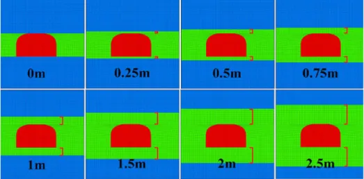
This weak geological condition has also led to the limitation of excavation into a certain height (Ozfirat et al., 2005). As a result, for thick coal seam, some of the remains coal thickness (RCT) located on top and bottom of the excavation. This can be beneficial for coal bed that is surrounded by weaker dominant rock as the harder remained coal can help to improve the stability of openings during the mining development and excavation. Many research works have been focused on developing mining technique for thick coal seam mine (Hebblewhite, 2005; Matsui et al., 2011;
Ozfirat et al., 2005; J. C. Wang et al., 2019). Some also including weak geological conditions (Sasaoka et al., 2015; Zarlin et al., 2012). However, few researchers have addressed the effect of remaining coal thickness (RCT) on the stability of gate-entry for longwall mining in the thick coal seam.
Figure 2.2. Mine layout of GDM in early stage.
Longitudinal Seam Depth
300m 250m 200m 150m 100m
29
Figure 2.3. General stratigraphy surrounding trial panel region
Figure 2.4. Layout of trial panel
Figure 2.2. shows the top view of mine layout of the study area. Due to the dip of the monocline structure of coal seam, longitudinal seam depth along mine panel can reach up to 300m in depth. GDM is currently developing a trial panel in order to have a better understanding of rock behavior surrounding the longwall panel. Figure 2.3.
demonstrate schematic of coal seam stratigraphy surrounding trial panel which highlight in read dash line. The trial panel is developed in seam BC range from 100m to 150m in depth. The dimension of this trial panel is 55m in width by 200m in length with 3m in height as shown in Figure 2.4. This chapter discusses the gate-entry stability of the trial panel under various stages of longwall development with two different depths of 100m and 150m. This research work consists of modelling this trial panel from the actual mine site to evaluate the appropriate support system for the gate-entry.
The first part of the paper focuses on the influence of RCT on maximizing the stability
30
of gate-entry. This part is targeted only for 100m in depth, as claystone in this area is weaker than coal. The second part of this research is to evaluate the appropriate support system for the trial panel during gate-entry development for 100m and 150m in depths.
For this particular part, the influence of RCT is incorporated in the support evaluation for 100m in depth only. The last section of this research work is to investigate the gate- entry stability under the influence of longwall panel extraction. This operation causes the increment of the stress surrounding gate-entry which is located near to the longwall face. This stress might exceed the maximum support capacity of the steel arch which results in the instability of gate-entry. Additional mobile support is necessary to maintain the stability of the gate. The length of additional support along the gate is evaluated in this section.
2.2.Modelling
In order to investigate the ground behavior, a series of numerical analyses are carried out by means of FLAC3D. This is a three-dimensional explicit finite-difference program which is designed for engineering mechanics computational. Material is introduced as zone element characterized by three-dimensional grid that can be constructed to fit the user’s needs. Linear and nonlinear law of stress/strain are given to allow each element to behave responding to the boundary condition. The modelling is constructed based on the actual condition in the mine site and specific case study.
Model validation is performed at the beginning of the numerical analysis to ensure the accuracy of the model by comparing the result from simulation to the actual result of field measurement.
2.2.1. General Model Description
The trial panel is modelled in FLAC3D. Only half of the trial panel, along the panel length, is modelled to save running time. The simulation is based on Mohr- Coulomb constitutive model. Due to the natural incline of the coal seam, the depth of this trial panel ranges from 100m to 150m. Both depths are adopted as case studies. The general dimensions of the model are described in Figure 2.5. Mining height is 3m of the coal seam is which surrounding by dominant rock claystone as the roof and floor.
Figure 2.6 shows the installation of the steel arch in the model. Beam structural elements are used to model steel arch for roof support along the gate-entry. Failure criterion is Mohr-Coulomb.