九州大学学術情報リポジトリ
Kyushu University Institutional Repository
三重項励起子制御基盤としての多孔性金属錯体
三重野, 寛之
https://doi.org/10.15017/1931877
出版情報:Kyushu University, 2017, 博士(工学), 課程博士 バージョン:
権利関係:
2017 Doctor thesis
Metal-organic frameworks as a platform for controlling triplet exciton dynamics
Hiroyuki Mieno
Department of Chemistry and Biochemistry Graduate School of Engineering
Kyushu University
Chapter 1 ... 5
1-1. Luminescence in organic materials ... 6
1-2. Metal-organic frameworks (MOFs) ... 10
1-3. Synthesis of MOFs ... 11
1-4. Luminescent MOFs ... 12
1-4-1. Metal-based emission ... 13
1-4-2. Ligand-based emission ... 13
1-4-3. Guest-related emission ... 14
1-4-4. Triplet excitons in MOFs ... 18
1-5. Outline of this thesis ... 21
Chapter 2 ... 27
2-1. Introduction ... 28
2-2. Calculation and design of organic linker ... 29
2-3. Experimental ... 30
2-3-1. Materials ... 30
2-3-2. Equipment ... 30
2-3-3. Calculation ... 31
2-3-4. Synthesis ... 32
2-4. Characterization of UiO-68-dpa ... 36
2-5. Results and discussion ... 39
2-5-1. Photophysical properties of H
2tpdc-dpa and UiO-68-dpa ... 39
2-5-2. Thermally activated delayed fluorescence of UiO-68-dpa ... 42
2-6. Conclusion ... 46
Chapter 3 ... 48
3-1. Introduction ... 49
3-2. Experimental ... 53
3-2-1. Synthesis ... 53
3-2-2. Film preparation ... 55
3-2-3. Equipment ... 55
3-2-4. Diffuse reflectance UV-vis measurements ... 55
3-2-5. Photoluminescence measurements of coronene-h
12@ZIF-8 and d
12@ZIF-8 and PMMA-doped films ... 56
3-2-6. Determination of k
pand k
nr(T) ... 57
3-2-7. Doping content of coronene in ZIF-8 ... 57
3-2-8. BET surface are analysis ... 58
3-3. Characterization ... 59
3-4. Results and discussion ... 63
3-4-1. Photophysical properties of coronene@ZIF-8 ... 63
3-4-2. Long-lived triplet excitons of coronene@ZIF-8 ... 66
3-5. Conclusion ... 71
Chapter 4 ... 75
4-1. Introduction ... 76
4-2. Experimental ... 77
4-2-1. Film preparation of coronene-d
12@ZIF-8 ... 77
4-2-2. Measurement system ... 77
4-2-3. Methods ... 78
4-3. Results ... 79
4-4. Conclusion ... 89
Chapter 5 ... 92
5-1. Summary of this thesis ... 93
5-2. Future perspective ... 94
Abbreviation list ... 99
Acknowledgements ... 102
Chapter 1
Introduction
1-1. Lu L relaxes probes,
1applicat chemica
L phospho defined singlet g the low crossing Reverse delayed fluoresc RISC in well kno
Figure 1
minescence Luminescen to the gro
1,2
optical tions
9–12hav al design wi
Luminescen orescence b
as a spin-a ground stat west triplet g (ISC)—is e ISC (RIS d fluorescen
cence (TAD ncreases wi
own as tripl
1-1. Jablonsk
e in organi nce in orga ound state.
switches,
3ve been ex ith the robu nce from based on the allowed radi e (S
0), and excited sta s spin forbi
C), a transi nce. Delaye DF) because ith temperat let-triplet an
ki diagram of
c materials anic materia Luminesce
3,4
organic xtensively d ust bonding organic m e spin states
iative transi phosphores te (T
1) to idden, but ition from d fluoresce e the popula ture. Single nnihilation (
f organic mo s
als is a rad ent organic c light-em developed b capabilities molecules i
s of the radi ition from t scence is de S
0. A trans it can be p T
1to S
1, c ence via RI
ation of sin ets produced
(TTA), can
olecules.
diative proc c materials mitting diod by taking fu s of carbon.
s classified ative transit the lowest s efined as a sition from partially all can also oc SC is calle glets produ d from the also lead to
cess in whic used in fl des (OLED ull advantag
d as eithe tion (Fig. 1- singlet excit spin-forbid
S
1to T
1— lowed by s
cur in som ed thermally uced from tr
collision of o delayed flu
Ch
ch an excit fluorescent
Ds),
5–8and ge of the u
er fluoresc -1). Fluores ted state (S dden transiti
—called inte spin-orbit c me cases, le y activated riplets that f triplets, a uorescence.
hapter 1
ted state imaging d other unlimited
ence or scence is S
1) to the ion from ersystem coupling.
ading to delayed undergo a process
.
Chapter 1
7
In OLEDs, recombination of injected electrons and holes generates excitons in a ratio of 25% singlets to 75% triplets based on the laws of spin statistics. Thus, the development of luminescent materials that can harvest triplets is important. However, if a large number of triplet excitons accumulates, which is prone to happen because of the generally long lifetimes of triplets, external quantum efficiency (η
EQE) tends to decrease because of TTA and singlet-triplet annihilation at high current densities. Therefore, it is necessary to develop luminescent materials that can efficiently and rapidly convert triplet excitons into emission to achieve a high photoluminescence quantum yield (Φ
PL) and short triplet lifetime.
Phosphorescent materials, which are able to utilize triplet excitons for emission, have been the focus of intense development since 2000, when Adachi et al. demonstrated an η
EQEof nearly 20% in the OLED using the phosphorescent emitter Ir(ppy)
3.
13Although phosphorescent materials can achieve Φ
PLof nearly 100% with relatively short triplet lifetimes, they require the inclusion of a rare metal in the chemical structure to obtain a high rate constant of radiative decay from T
1to S
0(k
p). Anthracene derivatives can be used as emitters to harvest triplets via TTA for emission without the need for rare metals, but the theoretical maximum internal quantum efficiency (η
IQE) based on such a strategy is limited to 62.5%. In 2009, the potential to use TADF, which up-converts T
1to S
1through RISC, in an OLED under electrical excitation was first demonstrated, but these initial devices had a low efficiency.
14Uoyama et al. then reported a series of highly efficient TADF emitters that are based on carbazolyl dicyanobenzene and exhibit Φ
PLof over 90%, allowing high η
EQEof 20%
comparable to phosphorescence OLEDs.
15Thus, TADF materials eliminate the need for rare metals while also achieving η
IQEof nearly 100% and short triplet lifetimes.
These triplet-harvesting emitters have also been adapted for use in other applications,
Chapter 1
such as sensors,
16optical storage,
4,12photocatalysts, photon up-conversion,
17bio-imaging,
18,19and reverse saturable absorption.
20In these applications, a long triplet lifetime is often more desirable than a short one. In the case of bio-applications, long-lived triplet excitons are useful because the emission by phosphorescence can be temporally separated from the excitation of the emitters by light, leading to lower-cost detectors such as charge-coupled devices (CCDs).
18To obtain reverse saturable absorption upon exposure to weak continuous incoherent light, the accumulation of a population of singlet or triplet excitons is important, so the long lifetimes of triplet excitons make triplets the superior candidate.
20In photon up-conversion, the probability of triplet-triplet fusion increases with the collision frequency of triplet excitons.
17Therefore, approaches to control triplet dynamics in molecules are important for these and new applications.
The dynamics of triplet excitons are primarily determined by processes falling into
four main categories: (1) ISC and (2) RISC between singlet and triplet states, (3) radiative
decay from T
1to S
0, and (4) nonradiative decay, which can be further divided into each
processes such as thermal deactivation, concentration quenching, and energy transfer to other
molecules. To rapidly harvest triplets for emission with a short lifetime, either the radiative
decay of triplets (3) or the RISC of singlets to triplets (2) must be accelerated. The former is
most commonly achieved through inclusion of heavy atoms in the chemical structure of an
emitter or the environment surrounding the emitters, because heavy atoms can accelerate both
the rate constant of ISC from singlets to triplets (k
isc) and of radiative decay from T
1to S
0(k
p)
(1 and 3). On the other hand, minimization of the energy gap between S
1and T
1is essential to
accelerate RISC (2) and attain emission through thermally activated delayed fluorescence,
which has a shorter lifetime than phosphorescence from metal-free aromatic compounds.
Chapter 1
9
If long-lived room-temperature phosphorescence is desired, nonradiative decay processes must be minimized because they generally far outpace the radiative decay of triplets.
Two methods to reduce nonradiative decay and increase Φ
PL, without increasing k
p, are the
introduction of emitters into rigid host matrices such as steroids
21,22and polymers
23,24and the
encapsulation of emitters in clathrate compounds like cyclodextrin
25,26and cucurbituril.
27Although these host matrices can be easily fabricated without necessitating the synthesis of
new emitters, they have some serious problems. For example, the use of cyclodextrin or
cucurbituril limits the available guest emitters to those that are small enough to fit in the
encapsulating molecule, and steroids and polymers are thermally instable because of phase
transitions and thermal decomposition. Therefore, I have considered metal-organic
frameworks (MOFs) as an alternative option for suppressing nonradiative decay processes
while solving some of the previously mentioned problems.
1-2. Me M were fir and S. K clusters between MOFs, choice o of MOF metal io
M applicat designin and mo synthesi sensors,
Figure 1 linkers.
etal-organic Metal-organ rst explored Kitagawa et and organi n the metal including th of compone Fs can be t ons.
35–38MOFs with tions such a ng organic l odifying the ized and st ,
42photovol
1-2. Example
c framewor nic framew d in the late
t al. almost ic linkers he
cations and he size and ents (Fig. 1- tuned by fu
h a high se as in gas se linkers and eir surfaces
tudied with ltaic cells,
43es of metal-o
rks (MOFs works (also 1990s as a at the same eld together d the functio shape of th 2).
30–34Furt unctionalizin
electivity a eparationan secondary . During th h the aim o
3,44
thermoel
organic fram s)
referred as a new class
time.
28,29M r by coordin onal groups he pores and thermore, th ng the orga
and extreme nd storage.
39building un he past dec
of opening lectric devi
meworks (MO
s porous co of porous m MOFs are co nation bonds of the linke d windows, he photophy anic linkers
ely large s
9–41
Such M nits (SBUs)
ade, a wide g new appli ces,
45hydro
OFs) using di
oordination materials by omposed of s formed at ers. The stru can be cont ysical and e s or changin
urface area MOFs have ,
36tuning sy e variety of ications, su ogen storage
ifferent meta
Ch
n polymers y O. M. Yag f a network
ambient co uctural prop trolled base electronic pr ng the sele
a have com been devel ynthetic con f MOFs ha uch as in c e,
41and cata
al cations and
hapter 1
(PCPs)) ghi et al.
of metal onditions perties of ed on the roperties ection of
mmercial loped by
nditions, ave been
chemical alysis.
46d organic
Chapter 1
11 1-3. Synthesis of MOFs
A wide variety of synthetic methods are possible because MOFs can be constructed by coordination bonds between metal ions or clusters and carboxylate, phosphonate,
47and amino groups. Although MOFs can be synthesized through self-assembly at ambient condition without heating, single crystals and high crystalline samples are commonly formed using solvothermal reactions, which are defined as reactions taking place in closed vessels above the boiling point of the reaction solvents.
48Using the SBUs which were reported by O. M.
Yaghi et al. systematized in 2008,
49a vast number of MOFs have been synthesized. Several other synthetic methods, such as microwave,
50electrochemical,
51and mechanochemical syntheses
52have been demonstrated with the aim of developing solvent-free, low-cost, environmentally friendly, and time-saving procedures. Developing ways to fabricate MOF thin films is also for application of MOFs to electronic devices such as photovoltaic cells
43,44and thermoelectric devices. In 2007, a step-by-step fabrication method for MOF thin films, which is called the layer-by-layer method, was developed by C. Wöll et al.
53The MOFs are grown by soaking a substrate functionalized with amine- or carboxyl-terminated self-assembled monolayers in alternating solutions of metal or organic ligand. Using this method, highly oriented MOF films and a tunable thickness can be obtained by altering the temperature or the number of immersion cycles.
Once MOFs are synthesized, an activation step of MOFs, which eliminates the residual organic linkers and reaction solvents within the pores of MOFs, must be performed.
The residual organic compounds often cause undesired influence on their photophysical
properties. Therefore, the activation step generally consists of the following steps: (1)
washing with organic solvents such as dimethylformamide (DMF) several times, (2) soaking
in organ evapora under v
1-4. Lu L such a electron on the Septemb compos and met emissio emissio
Figure 1
nic solvents ated, (3) rep
acuum.
minescent Luminescen as chemica nics.
63Of th
luminescen ber 2017).
sed of metal tal clusters.
n from lum n, (2) ligand
1-3. The orig
s for one day peating thes
MOFs nt MOFs ha al sensors he 30,000 M
nt propertie The origin l ions and o . MOFs can minescent d-based em
gins of lumin
y to exchan se steps for
ave been rep ,
54–57scint MOF-related es of MOF ns of lumin organic linke n also have
MOFs can mission, and
escence in M
nge DMF w r at least th
ported as p tillators,
58d publication F, according
nescence in ers, allowin
cavities tha n be classif (3) guest-re
MOFs
with other or hree times,
otential ma bioimaging ns to date, o g to the IS n MOFs ar ng for intera at can encap
fied into th elated emiss
rganic solve and (4) hea
terials for v g,
59–61pho one-tenth (a SI Web of re diverse b actions betw
psulate gue hree group sion (Fig. 1-
Ch
ents, which ating above
various app otocatalysts almost 4,00 Science (r because M ween organic
st molecule ps: (1) met
-3).
hapter 1
is easily e 100 ˚C
lications s,
62and 00) focus
retrieved
OFs are
c linkers
es. Thus,
tal-based
Chapter 1
13 1-4-1. Metal-based emission
There are many MOFs that have metal-based emission originating from luminescence of lanthanide ions.
64,65In such MOFs, organic linkers absorb the excitation light and transfer their energy to the lanthanide ions. The emission spectra and lifetime of these MOFs are determined by the properties of the metal. Therefore, the MOFs having metal-based emission often exhibit narrow emission spectra and long luminescence lifetimes, making them promising for sensing applications.
65After Reineke et al. firstly reported a MOF based on terbium ions in 1999,
66lanthanide-based MOFs have been well developed with a focus on potential applications such as luminescence and chemical sensing.
1-4-2. Ligand-based emission
Ligand-based emission includes metal-to-ligand and ligand-to-metal charge transfer (MLCT and LMCT, respectively) and luminescence directly from the organic ligands themselves, such as anthracene
67and pyrene derivatives.
68The design and synthesis of organic molecules with specific functional groups for linking, such as carboxyl or amine, are needed to construct new MOFs with ligand-based luminescence. This restriction of chemical functionality makes it difficult to develop their photophysical properties and applications.
There are also many reports describing aggregation,
69excimer formation,
70or self-quenching
of organic ligands,
70which lead to low Φ
PL, shifted emission colors, and decreased exciton
lifetimes. In 2014, H.-C. Zhou et al. reported PCN-94 (a Zr-based MOF), which uses the
fluorescent linker 4′,4′′′,4′′′ ′′,4′′′ ′′′ ′′-(ethene-1,1,2,2-tetrayl)tetrakis(([1,1′-biphenyl]-3-carbo-
xylic acid)) (H
4ETTC). The aromatic core tetraphenylethylene in H
4ETTC is well-known for
its aggregation-induced emission (AIE) characteristics.
71Because the formation of MOFs
Chapter 1
rigidifies AIE emitters, the nonradiative decay process caused by molecular motion is suppressed. As a result, PCN-94 exhibited a Φ
PLof almost 100% compared to 30% for H
4ETTC at the solid state. Therefore, if we carefully consider predicted MOF structures based on new luminescent organic linkers and SBUs, it is possible to avoid undesired photophysical effects such as self-quenching.
1-4-3. Guest-related emission
Guest-related emission is also divided into emission from the guest itself
57,72–75and emission from charge transfer or interaction between the guest and the organic linkers or metal clusters.
56,76,77Introduction or encapsulation of guest molecules into MOFs is an attractive strategy to acquire novel optical properties. The rigid frameworks of MOFs can immobilize organic ligands or encapsulate emitters, leading to the suppression of molecular diffusion and nonradiative decay. Moreover, molecular orientation can be expected because of the well-ordered structures of MOFs. Encapsulation of emitters in individual pores of MOFs can prevent the guest emitters from aggregating with each other. Both MOFs and guest emitters can be selected from a long list of existing ones, which means that synthesis of new luminescent organic ligands is not necessary. Although the introduction of guest emitters within MOF cavities reduces the MOF’s porosity, the concentration of guest emitters can be easily tuned by reducing the amount of emitter in the reaction solution used to fabricate the MOF (Table 1-1).
Table 1-2 illustrates that the history of emitters used in the pores of MOFs for
guest-related emission. Encapsulation of fluorescent aromatic guests in the pores of a MOF
was first demonstrated by M. J. Zaworotko et al. in 2002.
78In this report, exciplexes were
Chapter 1
15
formed between the organic linker Bipy (4,4’-bipyridyl) and the aromatic guest pyrene. Ten years after this report, G. Qian et al. achieved second-order nonlinear optical activity by introducing 4-(4-(diphenylamino)styryl)-1-dodecyl-pyridinium bromide (DPASD) in the pores of an anionic indium-based MOF named ZJU-28.
79ZJU-28 has two types of one dimensional (1D) channels along the a and c axes of about 6.1 × 6.1 and 7.1 × 8.5 Å, respectively, in which DPASD can be uniformly aligned. As a result, second harmonic generation was achieved when excited at 1,064 nm. They then continuously accomplished two-photon-pumped lasing in 2013.
72,80The aligned organic emitters 4-[p-(dimethylamino)styryl]-1-methylpyridinium (DMASM) in the 1D channels of bio-MOF-1 (Zn
8(Ad)
4(Bpdc)
6O·2Me
2HN
2(Ad: adeninate, Bpdc: 4,4’-biphenyldicarboxylic acid)) lead to the enhancement of Φ
PLfrom 1.5% (DMASM at solid state) to 25.9%
(DMASM@bio-MOF-1). Two-photon-pumped red lasing was observed when excited with a 1,064 nm near-infrared pulse laser. Furthermore, three-photon-pumped lasing and whispering gallery modes were realized in DMASM@ZJU-68 (ZJU-68: H
2[Zn
3O(C
17H
9NO
4)
3]) hexagonal prism crystals because of the highly orientation of DMASM as well as DMASM@bio-MOF-1 in 2016.
75A lasing threshold of ~224 nJ centered at 642.7 nm on excitation at 1,380 nm was achieved. Suppression of nonradiative decay processes including self-quenching and molecular orientation were accomplished owing to the well-ordered structures and isolation of emitter pores.
White luminescence is useful for lighting applications and white LEDs. However, it is
difficult to acquire white luminescence because monochromatic emitters rarely emit in the
entire visible region. Thus, dichromatic approaches have been mainly used because
color-rendering properties can be easily tuned by changing emitter concentrations.
Chapter 1
Luminescent MOFs are of great interest to attain efficient white emission because MOFs can encapsulate aromatic guests as an extra emitting molecule even after their synthesis. Highly efficient white-light-emitting solid-state materials were demonstrated by encapsulating a yellow phosphorescent Ir complex, Ir(ppy)
2(bpy)
+(ppy: 2-phenylpyridine, bpy:
2,2’-bipyridyl) into a mesoporous blue fluorescent cadmium-based MOF (Cd-MOF) with a Φ
PLof 20.4% and Commission International de I’Eclairage (CIE) coordinates of (0.31, 0.33).
73In 2015, A. Douhal et al. encapsulated two different aromatic guests coumarin 153 and nile red in the pores of Zr-NDC (NDC: 2,6’-naphthalenedicarboxylic acid).
69In this case, the highest Φ
PLof 33.2% with CIE coordinates of (0.32, 0.34) was achieved.
In these ways, a method of encapsulating luminescent aromatic guests into MOF pores is effective to explore a new class of luminescent materials and photophysical properties that are not successfully realized by aromatic guests or organic linker themselves.
Table 1-1. Advantages and disadvantages of metal-based emission, guest-related emission and ligand-based emission in MOFs.
Advantages Disadvantages Metal-based
emission
Narrow emission Long-lived emission (Ln)
High surface areas
Need to manage triplet energy level of organic linkers
Ligand-based emission
Maintain high porosity Reduce nonradiative decay
Molecular orientation Suppress molecular diffusion
Need to synthesize organic linkers Aggregation
Excimer formation Self-quenching
Guest-related emission
Suppress self-quenching Suppress aggregation Suppress molecular diffusion No need to synthesize new emitters
Reduce nonradiative decay Molecular orientation
Reduce porosity
Size matching
Table 1--2. History of guest-relateed emission
17 in MOFs
Ch hapter 1
Chapter 1
1-4-4. Triplet excitons in MOFs
Just like with organic emitters, triplets can be used for emission from MOFs. The inclusion of heavy atoms to accelerate phosphorescence can be accomplished in several ways.
Rare metals such as Ru, Ir, and Re have been incorporated in MOFs as the metal cluster, or metals can be included in the chemical structure of the organic linkers or MOF-entrapped guest molecules.
56,73,81–88However, triplet excitons in purely aromatic molecules that are used as the organic linkers or that are trapped in a MOF as guest molecules have barely been investigated despite the unique environment that a MOF provides.
67Following the history of triplet excitons in MOFs (Table 1-3), in 2014, [Cd
2(TIPA)
2Cl
4]·6DMF was the first MOF to exhibit phosphorescence from a pure aromatic linker, tri(4-imidazolylphenyl)amine (TIPA).
89However, phosphorescence cannot be observed at room temperature. X.-M. Ren et al.
reported the first room temperature phosphorescence (RTP) from a Mg-based MOF consisting of 1,1′-ethynebenzene-3,3′,5,5′-tert-racarboxylic acid (H
2EBTC) without any heavy atoms in 2016.
90Long-lived RTP (τ
p= 0.47 s) was demonstrated in Zn(BDC)(DMF)·(1-DMF) (BDC:
1,4-benzenedicarboxylic acid) by D. Yang et al. in the same year.
91They also synthesized Cd(m-BDC)(BIM) (m-BDC: 1,3-benzenedicarboxylic acid, BIM: benzimidazole) exhibiting the long lifetime of 0.75 s at room temperature.
92Although they mentioned that this Cd-based MOF exhibited reversible pH-responsive phosphorescence for pH values from 3 to 11, X-ray diffraction pattern (XRD) showed the structural changes occurred, indicating that the MOF decomposed under a high pH value. Subsequently, they achieved reversible full color RTP of an anionic MOF (AMOF-1), CdLi(m-BDC)
2(Me
2NH
2) (Me
2NH
2: dimethylamine), by a cation exchange with Mn
2+at different concentrations.
93In total, less than 5 papers demonstrating RTP without heavy atoms have been
Chapter 1
19
reported to date. Moreover, the dynamics of triplet excitons in MOFs have not been deeply
discussed. Since I expect that the separation and rigidity offered by a MOF can potentially
help suppress the nonradiative deactivation of triplets by self-quenching, thermal deactivation,
and energy transfer while not affecting k
p, introduction of triplet-based emitters as organic
linkers or encapsulated guest molecules is considered as an attractive option for controlling
and realizing triplet exciton dynamics. This strategy could provide a new platform not only
for investigating basic photophysical properties but also developing advanced applications for
luminescence.
Table 1--3. History of triplet excittons in MOF Fs
Ch hapter 1
Chapter 1
21 1-5. Outline of this thesis
The goal of this thesis is to develop new ways to control the harvesting of triplet excitons for luminescence by exploiting the rigid environments provided by MOFs. This thesis is organized as follows.
In Chapter 2, I utilize triplet excitons via TADF originating from ligand-based emission. A Zr-based MOF (namely UiO-68-dpa) is synthesized based on the newly designed organic linker with TADF properties (H
2tpdc-dpa). The linker consists of diphenylamine as an electron-donating moiety and carboxyl groups as both electron-accepting moieties and linkers that bond to the Zr clusters. From this new MOF, TADF characteristics are obtained at room temperature. The interactions among organic linkers, neighboring organic linkers, and metal clusters are discussed in terms of their effects on the emission spectrum, self-quenching, and Φ
PL.
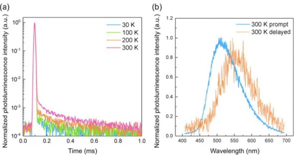
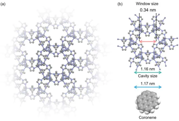
In Chapter 3, I obtain long-lived room-temperature phosphorescence from MOFs having guest-related emission. Long-lived phosphorescence is demonstrated with an emission lifetime of 22.4 s at room temperature from coronene-d
12encapsulated in the zeolitic imidazolate framework ZIF-8 (coronene-d
12@ZIF-8). The guest emitter coronene-d
12is well isolated in the rigid framework of ZIF-8, enabling long-lived triplet excitons even at temperatures higher than 300 K. Thermally activated delayed fluorescence is also demonstrated at temperatures over 300 K.
In Chapter 4, I demonstrate a new strategy to control the dynamics of triplet excitons
in organic emitters by using gases to influence emitters encapsulated in a metal organic
framework. Because MOFs intrinsically have a large number of pores that can accommodate
gases and aromatic molecules, the heavy-atom gas xenon (Xe) can be introduced into
Chapter 1
coronene-d
12@ZIF-8 to influence the emission properties of coronene. Triplet excitons accumulated by photoexcitation of coronene-d
12under vacuum can be rapidly converted into emission immediately after introduction of Xe. I can easily regulate the timing and speed of extraction of the accumulated triplet excitons as emission by introducing gas mixtures with various concentrations of Xe.
In Chapter 5, the thesis is summarized, and future prospects are discussed.
23 References
[1] Y. Pak, K. Swamy and J. Yoon, Sensors, 2015, 15, 24374–24396.
[2] M. Fernández-Suárez and A. Y. Ting, Nat. Rev. Mol. Cell Biol., 2008, 9, 929–943.
[3] T. Mutai, H. Satou and K. Araki, Nat. Mater., 2005, 4, 685–687.
[4] M. Irie, T. Fukaminato, T. Sasaki, N. Tamai and T. Kawai, Nature, 2002, 420, 759–760.
[5] G. M. Farinola and R. Ragni, Chem. Soc. Rev., 2011, 40, 3467–3482.
[6] X. Yang, X. Xu and G. Zhou, J. Mater. Chem. C, 2015, 3, 913–944.
[7] Y. Tao, C. Yang and J. Qin, Chem. Soc. Rev., 2011, 40, 2943–2970.
[8] P.-T. Chou and Y. Chi, Chem. Eur. J., 2007, 13, 380–395.
[9] A. Kishimura, T. Yamashita, K. Yamaguchi and T. Aida, Nat. Mater., 2005, 4, 546–549.
[10] S. Hirata, K. S. Lee and T. Watanabe, Adv. Funct. Mater., 2008, 18, 2869–2879.
[11] H. Sun, S. Liu, W. Lin, K. Y. Zhang, W. Lv, X. Huang, F. Huo, H. Yang, G. Jenkins, Q. Zhao and W. Huang, Nat. Commun., 2014, 5, 3601.
[12] Y. Liang, A. S. Dvornikov and P. M. Rentzepis, Proc. Natl. Acad. Sci., 2003, 100, 8109–8112.
[13] C. Adachi, M. A. Baldo, S. R. Forrest and M. E. Thompson, Appl. Phys. Lett., 2000, 77, 904–
906.
[14] A. Endo, M. Ogasawara, A. Takahashi, D. Yokoyama, Y. Kato and C. Adachi, Adv. Mater., 2009, 21, 4802–4806.
[15] H. Uoyama, K. Goushi, K. Shizu, H. Nomura and C. Adachi, Nature, 2012, 492, 234–238.
[16] Y. Yang, K. Z. Wang and D. Yan, ACS Appl. Mater. Interfaces, 2016, 8, 15489–15496.
[17] C. Ye, L. Zhou, X. Wang and Z. Liang, Phys. Chem. Chem. Phys., 2016, 18, 10818–10835.
[18] Q. le Masne de Chermont, C. Chaneac, J. Seguin, F. Pelle, S. Maitrejean, J.-P. Jolivet, D. Gourier, M. Bessodes and D. Scherman, Proc. Natl. Acad. Sci., 2007, 104, 9266–9271.
[19] M. Palner, K. Pu, S. Shao and J. Rao, Angew. Chem. Int. Ed., 2015, 54, 11477–11480.
[20] S. Hirata, K. Totani, T. Yamashita, C. Adachi and M. Vacha, Nat Mater, 2014, 13, 938–946.
[21] S. Hirata, K. Totani, J. Zhang, T. Yamashita, H. Kaji, S. R. Marder, T. Watanabe and C. Adachi, Adv. Funct. Mater., 2013, 23, 3386–3397.
[22] S. Hirata and M. Vacha, Adv. Opt. Mater., 2017, 5, 1600996.
[23] S. Reineke, N. Seidler, S. R. Yost, F. Prins, W. A. Tisdale and M. A. Baldo, Appl. Phys. Lett., 2013, 103, 93302.
[24] D. Lee, O. Bolton, B. C. Kim, J. H. Youk, S. Takayama and J. Kim, J. Am. Chem. Soc., 2013, 135, 6325–6329.
[25] S. Scypinski and L. J. C. Love, Anal. Chem., 1984, 56, 322–327.
[26] J. L. Kropp, W. R. Dawson and R. Dawson, J. Phys. Chem., 1987, 71, 4499–4506.
[27] P. Montes-Navajas and H. Garcia, J. Phys. Chem. C, 2010, 114, 2034–2038.
[28] M. Kondo, T. Yoshitomi, H. Matsuzaka, S. Kitagawa and K. Seki, Angew. Chem. Int. Ed., 1997, 36, 1725–1727.
[29] H. Li, M. Eddaoudi, T. L. Groy and O. M. Yaghi, J. Am. Chem. Soc., 1998, 120, 8571–8572.
[30] D. Britt, H. Furukawa, B. Wang, T. G. Glover and O. M. Yaghi, Proc. Natl. Acad. Sci., 2009, 106, 20637–20640.
[31] J. A. Mason, M. Veenstra and J. R. Long, Chem. Sci., 2014, 5, 32–51.
[32] http://www.chemtube3d.com/solidstate/MOF-ZIF8.htm
[33] W. Morris, B. Volosskly, S. Demir, F. Gándara, P. L. McGrier, H. Furukawa, D. Cascio, J. F.
Stoddart and O. M. Yaghi, Inorg. Chem., 2012, 51, 6643-6445.
[34] P. Horcajada, T. Chalati, C. Serre, B. Gillet, C. Sebrie, T. Baati, J. F. Eubank, D. Heurtaux, P.
Clayette, C. Kreuz, J.-S. Chang, Y. K. Hwang, V. Marsaud, P.-N. Bories, L. Cynober, S. Gil, G.
Férey, P. Couvreur and R. Gref, Nat. Mater., 2010, 9, 172-178.
[35] S. Kitagawa, Angew. Chem. Int. Ed., 2015, 54, 10686–10687.
[36] D. J. Tranchemontagne, J. L. Mendoza-Cortés, M. O’Keeffe and O. M. Yaghi, Chem. Soc. Rev., 2009, 38, 1257-1283.
[37] N. Stock and S. Biswas, Chem. Rev., 2012, 112, 933–969.
[38] H. Furukawa, K. E. Cordova, M. O’Keeffe and O. M. Yaghi, Science, 2013, 341, 1230444.
[39] B. Li, H.-M. Wen, W. Zhou and B. Chen, J. Phys. Chem. Lett., 2014, 5, 3468–3479.
[40] J.-R. Li, R. J. Kuppler and H.-C. Zhou, Chem. Soc. Rev., 2009, 38, 1477–1504.
[41] L. J. Murray, M. Dincă and J. R. Long, Chem. Soc. Rev., 2009, 38, 1294–1314.
[42] L. E. Kreno, K. Leong, O. K. Farha, M. Allendorf, R. P. Van Duyne and J. T. Hupp, Chem. Rev., 2012, 112, 1105–1125.
[43] D. Y. Lee, D. V. Shinde, S. J. Yoon, K. N. Cho, W. Lee, N. K. Shrestha and S. H. Han, J. Phys.
Chem. C, 2014, 118, 16328–16334.
[44] R. Kaur, K.-H. Kim, A. K. Paul and A. Deep, J. Mater. Chem. A, 2016, 4, 3991–4002.
[45] K. J. Erickson, F. Léonard, V. Stavila, M. E. Foster, C. D. Spataru, R. E. Jones, B. M. Foley, P. E.
Hopkins, M. D. Allendorf and A. A. Talin, Adv. Mater., 2015, 27, 3453–3459.
[46] J. Lee, O. K. Farha, J. Roberts, K. A. Scheidt, S. T. Nguyen and J. T. Hupp, Chem. Soc. Rev., 2009, 38, 1450–1459.
[47] T. Zheng, Z. Yang, D. Gui, Z. Liu, X. Wang, X. Dai, S. Liu, L. Zhang, Y. Gao, L. Chen, D.
Sheng, Y. Wang, J. Diwu, J. Wang, R. Zhou, Z. Chai, T. E. Albrecht-Schmitt and S. Wang, Nat.
Commun., 2017, 8, 15369.
[48] A. Rabenau, Angew. Chem. Int. Ed., 1985, 24, 1026–1040.
[49] M. O’Keeffe, M. A. Peskov, S. J. Ramsden and O. M. Yaghi, Acc. Chem. Res., 2008, 41, 1782–
1789.
25
[50] J. Klinowski, F. A. Almeida Paz, P. Silva and J. Rocha, Dalt. Trans., 2011, 40, 321–330.
[51] I. Stassen, M. Styles, T. Van Assche, N. Campagnol, J. Fransaer, J. Denayer, J. C. Tan, P.
Falcaro, D. De Vos and R. Ameloot, Chem. Mater., 2015, 27, 1801–1807.
[52] T. Friščić, I. Halasz, P. J. Beldon, A. M. Belenguer, F. Adams, S. A. J. Kimber, V. Honkimäki and R. E. Dinnebier, Nat. Chem., 2012, 5, 66–73.
[53] O. Shekhah, H. Wang, S. Kowarik, F. Schreiber, M. Paulus, M. Tolan, C. Sternemann, F. Evers, D. Zacher, R. A. Fischer and C. Wöll, J. Am. Chem. Soc., 2007, 129, 15118–15119.
[54] B. Zhao, X.-Y. Chen, P. Cheng, D.-Z. Liao, S.-P. Yan and Z.-H. Jiang, J. Am. Chem. Soc., 2004, 126, 15394–15395.
[55] K. L. Wong, G. L. Law, Y. Y. Yang and W. T. Wong, Adv. Mater., 2006, 18, 1051–1054.
[56] Y. Takashima, V. M. Martínez, S. Furukawa, M. Kondo, S. Shimomura, H. Uehara, M.
Nakahama, K. Sugimoto and S. Kitagawa, Nat. Commun., 2011, 2, 168.
[57] N. Yanai, K. Kitayama, Y. Hijikata, H. Sato, R. Matsuda, Y. Kubota, M. Takata, M. Mizuno, T.
Uemura and S. Kitagawa, Nat. Mater., 2011, 10, 787–793.
[58] F. P. Doty, C. A. Bauer, A. J. Skulan, P. G. Grant and M. D. Allendorf, Adv. Mater., 2009, 21, 95–101.
[59] K. M. L. Taylor, W. J. Rieter and W. Lin, J. Am. Chem. Soc., 2008, 130, 14358–14359.
[60] K. M. L. Taylor, A. Jin and W. Lin, Angew. Chem. Int. Ed., 2008, 47, 7722–7725.
[61] P. Horcajada, R. Gref, T. Baati, P. K. Allan, G. Maurin, P. Couvreur, G. Férey, R. E. Morris and C. Serre, Chem. Rev., 2012, 112, 1232–1268.
[62] Y. Li, H. Xu, S. Ouyang and J. Ye, Phys. Chem. Chem. Phys., 2016, 18, 7563–7572.
[63] D. Chen, H. Xing, Z. Su and C. Wang, Chem. Commun., 2016, 52, 2019–2022.
[64] C. Pagis, M. Ferbinteanu, G. Rothenberg and S. Tanase, ACS Catal., 2016, 6, 6063–6072.
[65] Y. Cui, B. Chen and G. Qian, Coord. Chem. Rev., 2014, 273–274, 76–86.
[66] T. M. Reineke, M. Eddaoudi, M. O’Keeffe and O. M. Yaghi, Angew. Chem. Int. Ed., 1999, 38, 2590–2594.
[67] H. S. Quah, W. Chen, M. K. Schreyer, H. Yang, M. W. Wong, W. Ji and J. J. Vittal, Nat.
Commun., 2015, 6, 7954.
[68] W. Cho, H. J. Lee, G. Choi, S. Choi and M. Oh, J. Am. Chem. Soc., 2014, 136, 12201–12204.
[69] M. Gutiérrez, F. Sánchez and A. Douhal, J. Mater. Chem. C, 2015, 3, 11300–11310.
[70] M. Gutiérrez, F. Sánchez and A. Douhal, Phys. Chem. Chem. Phys., 2016, 18, 5112–5120.
[71] Z. Wei, Z. Gu, R. K. Arvapally, Y. Chen, R. N. McDougald, J. F. Ivy, A. A. Yakovenko, D. Feng, M. A. Omary and H. Zhou, J. Am. Chem. Soc., 2014, 136, 8269–8276.
[72] J. Yu, Y. Cui, H. Xu, Y. Yang, Z. Wang, B. Chen and G. Qian, Nat. Commun., 2013, 4, 2719.
[73] C. Sun, X. Wang, X. Zhang, C. Qin, P. Li, Z. Su, D.-X. Zhu, G.-G. Shan, K.-Z. Shao, H. Wu and
J. Li, Nat. Commun., 2013, 4, 2717.
[74] J. W. Ye, H. L. Zhou, S. Y. Liu, X. N. Cheng, R. B. Lin, X. L. Qi, J. P. Zhang and X. M. Chen, Chem. Mater., 2015, 27, 8255–8260.
[75] H. He, E. Ma, Y. Cui, J. Yu, Y. Yang, T. Song, C.-D. Wu, X. Chen, B. Chen and G. Qian, Nat.
Commun., 2016, 7, 11087.
[76] V. Martínez-martínez, S. Furukawa, Y. Takashima and I. L. Arbeloa, J. Phys. Chem. C, 2012, 116, 26084–26090.
[77] P. L. Feng, K. Leong and M. D. Allendorf, Dalt. Trans., 2012, 41, 8869–8877.
[78] B. D. Wagner, G. J. McManus, B. Moulton and M. J. Zaworotko, Chem. Commun., 2002, 5, 2176–2177.
[79] J. Yu, Y. Cui, C. Wu, Y. Yang, Z. Wang, M. O’Keeffe, B. Chen and G. Qian, Angew. Chem. Int.
Ed., 2012, 51, 10542–10545.
[80] T. Song, J. Yu, Y. Cui, Y. Yang and G. Qian, Dalt. Trans., 2016, 45, 4218–4223.
[81] Z. Xie, L. Ma, K. E. DeKrafft, A. Jin and W. Lin, J. Am. Chem. Soc., 2010, 132, 922–923.
[82] S. M. Barrett, C. Wang and W. Lin, J. Mater. Chem., 2012, 22, 10329–10334.
[83] W. A. Maza and A. J. Morris, J. Phys. Chem. C, 2014, 118, 8803–8817.
[84] W. A. Maza, R. Padilla and A. J. Morris, J. Am. Chem. Soc., 2015, 137, 8161–8168.
[85] Y. Zhao, H. Xu, Y. Fu, K. Shao, S. Yang, Z.-M. Su, X.-R. Hao, D.-X. Zhu and E.-B. Wang, Cryst.
Growth Des., 2008, 8, 3566–3576.
[86] C. L. Whittington, L. Wojtas and R. W. Larsen, Inorg. Chem., 2014, 53, 160–166.
[87] X.-L. Qi, S.-Y. Liu, R.-B. Lin, P.-Q. Liao, J.-W. Ye, Z. Lai, Y. Guan, X.-N. Cheng, J.-P. Zhang and X.-M. Chen, Chem. Commun., 2013, 49, 6864–6866.
[88] S. Zhan, M. Li, W. Ng and D. Li, Chem. Eur. J., 2013, 19, 10217–10225.
[89] S. Yuan, Y. K. Deng and D. Sun, Chem. Eur. J., 2014, 20, 10093–10098.
[90] L. Zhai, W.-W. Zhang, J.-L. Zuo and X.-M. Ren, Dalt. Trans., 2016, 45, 11935–11938.
[91] X. Yang and D. Yan, Chem. Sci., 2016, 7, 4519–4526.
[92] Y. Yang, K. Z. Wang and D. Yan, ACS Appl. Mater. Interfaces, 2016, 8, 15489–15496.
[93] X. Yang and D. Yan, J. Mater. Chem. C, 2017, 5, 7898–7903.
[94] Y. Cui, R. Song, J. Yu, M. Liu, Z. Wang, C. Wu, Y. Yang, Z. Wang, B. Chen and G. Qian, Adv.
Mater., 2015, 27, 1420–1425.
[95] T. Xia, T. Song, Y. Cui, Y. Yang and G. Qian, Dalt. Trans., 2016, 45, 18689–18695.
[96] D. Yan, Y. Tang, H. Lin and D. Wang, Sci. Rep., 2015, 4, 4337.
[97] X. Liu, L. Zhai, W.-W. Zhang, J.-L. Zuo, Z.-X. Yang and X.-M. Ren, Dalt. Trans., 2017, 46,
7953–7959.
H Hiroyuki M
Thermal of a Zr
Mieno, Ryo Che
C
lly activa r-based m
ota Kabe, emical Com
Chapter
ated dela metal-org
Mark D. A mmunicat
r 2
ayed fluor anic fram
Allendorf, tions, in pr
rescence mework
, and Chih ress.
e
haya Adacchi
Chapter 2
2-1. Introduction
Organic molecules exhibiting TADF are being actively developed for highly efficient OLEDs.
1Capable of harvesting 100% of excitons, TADF molecules produce delayed fluorescence when singlet excitons produced by the reverse intersystem crossing of triplet excitons radiatively decay. Delayed fluorescence is also useful for bioimaging applications because the delayed emission can be temporally separated from the excitation light.
2,3However, most organic emitters needed to be dispersed into solvents or host molecules to avoid concentration quenching of the emission. Furthermore, the charge-transfer emission of TADF molecules is strongly affected by the polarity of solvents or host molecules and often quenched in polar solvents like water, complicating film optimization and hindering biological applications.
The high surface area, porosity, thermal stability, chemical stability, and structural
tunability of MOFs possibly offer a way to modify some of these effects.
4MOFs are hybrid
porous materials composed of metal-clusters and organic linkers. Because their rigid
frameworks inhibit nonradiative deactivation
5,6and prevent aggregation of emitters,
7,8solid-state emission can be observed by introducing luminescent organic molecules into
MOFs as linkers or guests.
9Such solid-state luminescent MOFs are useful for bioapplications,
including bioimaging
10and drug delivery
11, photocatalysts
12and chemical sensors
13. Although
a wide variety of luminescent MOFs have been demonstrated to date and I previously showed
that guest molecules within MOF pores can exhibit TADF,
7a MOF exhibiting intrinsic TADF
has never been reported. MOFs exhibiting TADF could be an avenue to achieving higher
thermal and chemical stability than in conventional TADF molecules and may offer new ways
to tune TADF properties, such as delayed lifetime and emission spectrum, by varying the
Chapter 2
29 selection of metals and size of pores.
Here, I design a new linker with TADF properties for use in MOFs. The linker, H
2tpdc-dpa, has both electron-donating and electron-accepting moieties with a large dihedral angle between them. Based on this TADF linker, I developed a zirconium-based MOF that is the first to exhibit intrinsic TADF at room temperature.
2-2. Calculation and design of organic linker
Most TADF molecules consist of electron donor and acceptor units separated by a large dihedral angle to effectively separate the highest occupied molecular orbital (HOMO) and the lowest unoccupied molecular orbital (LUMO) of the molecule. The resulting small spatial overlap between the HOMO and the LUMO leads to a small energy gap between the lowest singlet excited state and the lowest triplet excited state (ΔE
ST).
Organic linkers used in MOFs often contain a carboxyl unit as the functional group that coordinates with the metal center. Since a carboxyl group acts as an electron acceptor, TADF emission might be obtained by adding an electron-donating unit to the linker to induce the spatial separation of the HOMO and LUMO. For example, the organic linker H
2tpdc-NH
2, which was used in the MOF (UiO-68-NH
2), contains an electron-accepting carboxylic acid and an electron-donating amino group.
14The ΔE
STof this linker was calculated to be as high as 0.66 eV using density functional theory (B3LYP/6-31G level). This large value is the result of a small dihedral angle between the donor and acceptor moieties (Fig. 2-1a) and is too high to enable the efficient conversion of triplet excitons to singlet excitons at room temperature.
To obtain a smaller ΔE
ST, I designed the novel linker H
2tpdc-dpa, which consists of carboxyl
and diphenyl amino moieties. A large steric hindrance between the donor and acceptor
moieties ΔE
STof
Figure calculate
2-3. Exp 2-3-1. M A received 2,5-dibr
2-3-2. E
1
spectrom corder.
s induces a f 0.2 eV (Fig
2-1. (a) HO ed at the B3L
perimental Materials
All starting d. 4,4”-D romo-N,N-d
Equipment
1
H and
13C meter. Elem Solution an
separation g. 2-1b).
OMO and L LYP/6-31G l
l
g materials Dimethoxyc diphenylami
C NMR sp mental analy
nd thin-film
of HOMO a
LUMO distri evel. (b) Sch
were purch arbonyl-2’- inobenzene
pectra were yses (C, H m UV–vis a
and LUMO
ibutions of hematic struc
hased from -amino-[1,1
(1) were pr
e recorded H, N) were
absorption s
O, leading to
H
2tpdc-NH cture of UiO-
commercia
’:4’,1”]terp repared as d
on a Bru carried out spectra wer
o a moderate
H
2(left) and -68-dpa
al suppliers phenyl, H
described in
uker AVAN t using a Y
e recorded
C
ely small ca
d H
2tpdc-dp
s and were H
2tpdc-NH
2n the literatu
NCE III 50 Yanaco MT
on a Perki
Chapter 2
alculated
pa (right)
used as
2
, and ure
14,15.
00 MHz T-5 CHN
in-Elmer
Chapter 2
31
Lambda 950-PKA UV–vis spectrophotometer. Photoluminescence quantum yields were obtained from an absolute photoluminescence quantum yield measurement system (Quantaurus-QY C11347-01, Hamamatsu Photonics). The photoluminescence decay characteristics of the solution samples were recorded using a fluorescence lifetime measurement system (Quantaurus-Tau, Hamamatsu Photonics). The photoluminescence decay characteristics of the film samples were recorded under vacuum using a streak camera (C4334, Hamamatsu Photonics) equipped with a N
2gas laser (KEN-X, Usho, λ = 337 nm, pulse width
≈ 500 ps, repetition rate = 20 Hz) as the excitation source. Low-temperature measurements
were conducted using a cryostat (CRT-006-2000, Iwatani Industrial Gases). X-ray diffraction patterns were obtained using a Rigaku Ultima IV diffractometer with CuKα radiation.
Thermogravimetric analysis data were measured with a rate of 10 °C/min using a Bruker TG-DTA2400SA analyser.
2-3-3. Calculation
All quantum chemical calculations were performed using the Gaussian 09 program
package Geometry optimization was carried out using the B3LYP functional with the
6-31G(d) basis set. Low-lying excited singlet and triplet states were computed using the
optimized structures with time-dependent density functional theory (TD-DFT) at the same
level.
2-3-4. S Scheme
4,4”-Dim T phenylb (diphen (Pd(dpp 2 days u CH
2Cl
2The re (hexane
1
Hz, 2H) 1H), 7.2 28 Hz, 6 144.31, 128.04,
Synthesis 2-1.
methoxycar To a dioxa boronic aci nylphosphin
pf)Cl
2·CH
2C under Ar. T . The organ esulting cr e:CH
2Cl
2=
1
H NMR (5 ), 7.63 (d, J 28 (d, J = 8 6H).
13C NM
144.12, 14 126.95, 12
rbonyl-2’-d ane (50 mL id (0.6 g, o)ferrocene Cl
2) (0.12 g The resultin nic layer wa rude produ
4:1) to affor 500 MHz, C J = 8.2 Hz,
.2 Hz, 2H), MR: (125 M
41.25, 138.
24.47, 122.2
diphenylami L) solution , 3.3 mmo e]dichloropa
, 0.15 mmo ng solution as filtered w uct was su rd 0.43 g of CDCl
3, 25 ° 2H), 7.60 ( 7.08 (t, 4H MHz, CDCl
.92, 132.32 21, 121.83,
ino-[1,1’:4’, n of 1 (0.6
ol), K
3PO
4alladium(II) ol) were add was cooled with celite a
ubjected t f 2 in a 56%
°C): δ (ppm s, 1H), 7.54 H), 6.88 (d, J
l
3, 25 °C): δ 2, 130.15,
, 52.18, 52.
,1”]terpheny 60 g, 1.5
4
(1.27 g, ) comple ded. The mix d to room te and concen to silica g
% yield as a m) = 8.08 (d 4 (d, J = 8.0
J = 7.8 Hz, δ (ppm) = 1
129.27, 129 .02. MS (M
yl (2) mmol), 4-(
, 6.0 mmo ex with
xture was h emperature trated unde gel column
yellowish w d, J = 8.2 H
0 Hz, 1H), 7 4H), 6.84 ( 67.00, 166.
9.22, 128.8 MALDI-TOF
C
(methoxyca mol) and [ dichloro heated to 10 and extrac er reduced p
n chromat white solid.
Hz, 2H), 7.80 7.41 (d, J = (t, 2H), 3.9 88, 147.21, 88, 128.51,
F-MS): m/z
Chapter 2
arbonyl)- 1,1’-bis- methane 00 °C for ted with pressure.
tography
0 (d, 8.1
= 8.0 Hz,
1 (d, J =
, 145.66,
128.47,
z 512.76
[M]
+El 5.31; N,
Figure 2
lemental an , 2.70
2-2.
1H and
1nalysis: calc
3
C NMR spe
d. for C
34H
ectra of comp
33 H
27NO
4: C, 7
pound 2.
79.5; H, 5.330; N, 2.73;
C
; found: C,
Chapter 2
79.3; H,
Chapter 2
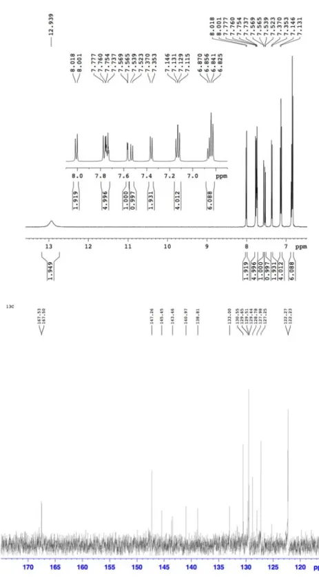
4,4”-Dicarboxyl-2’-diphenylamino-[1,1’:4’,1”]terphenyl (H
2tpdc-dpa)
To a dioxane (20 mL) solution of 2 (0.20 g, 0.4 mmol), KOH (0.17 g, 3.0 mmol) in aqueous solution (10 mL) was added and refluxed overnight. The resulting clear solution was cooled to room temperature and treated with hydrochloric acid (concentrated HCl) through an addition funnel with ice bath until the solution reached a pH of 1. Then, the mixture was stirred for another 1 hour. Finally, the precipitate was filtered and dried under vacuum to give H
2tpdc-dpa as a yellow powder (0.18 g, 93%).
1
H NMR (500 MHz, DMSO, 25 °C): δ (ppm) = 12.9 (br, 2H), 8.01 (d, J = 8.5 Hz, 2H), 7.75 (m, 5H), 7.57 (d, J = 8.7 Hz, 1H), 7.53 (d, J = 8.0 Hz, 1H), 7.36 (d, J = 8.3 Hz, 2H), 7.13 (t, 4H), 6.85 (t, 6H).
13C NMR: (125 MHz, CDCl3, 25 °C): δ (ppm) = 167.53, 167.50, 147.26, 145.45, 143.46, 140.97, 138.81, 133.00, 130.55, 129.65, 129.51, 129.44, 128.78, 127.98, 127.25, 122.27, 122.23. MS (MALDI-TOF-MS): m/z 484.69 [M]
+Elemental analysis: calcd.
for C
32H
23NO
4: C, 79.2; H, 4.74; N, 2.88; found: C, 79.0; H, 4.87; N, 2.87
Figure 2 2-3.
1H and
13C NMR speectra of H
2tp
35 pdc-dpa.
C
Chapter 2
Chapter 2
Synthesis of UiO-68-NH
2and UiO-68-dpa
In a 6-dram vial, a DMF solution (10 mL) of H
2tpdc-NH
2(67 mg, 0.2 mmol) or H
2tpdc-dpa (97 mg, 0.2 mmol), ZrCl
4(57 mg, 0.2 mmol), benzoic acid (UiO-68-NH
2: 488 mg, 4.0 mmol; UiO-68-dpa: 122 mg, 1.0 mmol) and water (18 μL) was heated to 70 °C for 3 days. After cooling to room temperature, the precipitates were isolated by centrifugation. The solids were suspended in DMF (20 mL). After standing at room temperature for 1 day, the suspensions were centrifuged and the solvent was decanted off. This treatment was repeated five times to remove the unreacted organic linker. Afterwards the same procedure was performed with ethanol (20 mL × 3). The solids were dried at 120 °C for 12 h under reduced pressure.
Elemental analysis of UiO-68-dpa: calcd. for Zr
6O
5(OH)
3(H
2tpdc-dpa)
5.5·11H
2O: C, 59.8; H, 3.98; N, 2.18; found: C, 59.3; H, 3.70; N, 2.31
2-4. Characterization of UiO-68-dpa
Both H
2tpdc-NH
2and H
2tpdc-dpa linkers and their Zr-based MOFs (UiO-68-NH
2and UiO-68-dpa, respectively) were synthesized and characterized (Scheme 2-1). The powder
X-ray diffraction pattern of UiO-68-dpa reveals the crystallinity of the MOF, and the
diffraction peaks are similar to those of UiO-68-NH
2, which has two different-shaped cavities
in the structure (Figs. 2-1 and 2-4).
14The nitrogen isotherms of UiO-68-dpa, with a step at
P/P
0of 0.2, are also consistent with the presence of two types of cavities (Fig. 2-5). The BET
surface area of UiO-68-dpa was calculated to be 1455 m
2/g, which is smaller than that of
UiO-68-2CH
3(2470 m
2/g)
15because the diphenylamine of H
2tpdc-dpa partially occupies the
cavities. Scanning electron microscopy images reveal an octahedral morphology for
UiO-68 UiO-68 decomp 2-7). Th
Figure Thermog
Figure 2
8-dpa with a 8-dpa show poses at aro he small we
2-4. (Left) gravimetric a
2-5. Nitrogen
a particle si ws no subs ound 650 K ight loss at
) XRD pa analysis of H
n adsorption
ize of less th stantial wei K, indicating
400 K is du
tterns of U H
2tpdc-dpa (
isotherms of
37 han 10 μm ight loss u g that UiO ue to residu
UiO-68-NH
2(blue) and Ui
f UiO-68-dp
(Fig. 2-6). T up to 700
-68-dpa ha al DMF.
2
(blue) an iO-68-dpa (r
pa at 77K.
Thermograv K even th as good the
nd UiO-68- red).
C
vimetric an hough H
2tp ermal stabil
-dpa (red).
Chapter 2
alysis of pdc-dpa ity (Fig.
(Right)
Figure 2
Figure 2
2-6. SEM im
2-7. Thermog
mages of UiO
gravimetric a
-68-dpa with
analysis of H
h scale bars
H
2tpdc-dpa (
of (a) 40 μm
(blue) and Ui
m and (b) 10 μ
iO-68-dpa (r
C
μm.
red).
Chapter 2
Chapter 2
39 2-5. Results and discussion
2-5-1. Photophysical properties of H
2tpdc-dpa and UiO-68-dpa
UV-vis absorption and emission spectra of H
2tpdc-dpa in tetrahydrofuran (THF) solution and UiO-68-dpa dispersed in THF are shown in Fig. 2-8a, and the photophysical properties are summarized in Table 2-1. The absorption spectrum of H
2tpdc-dpa shows two absorption peaks at 291 and 370 nm, which are attributable to π-π* and charge-transfer transitions, respectively. The H
2tpdc-dpa linker exhibits broad charge-transfer emission with a peak at 481 nm in THF solution. The phosphorescence spectrum of H
2tpdc-dpa in THF was observed at 77 K (Fig. 2-8b), and the ΔE
STwas estimated to be 0.24 eV from the offset between the fluorescence and phosphorescence spectra, which is good agreement with the calculation results.
Although H
2tpdc-dpa also exhibits charge-transfer emission when doped in a solid-state film of PMMA, the emission peak maximum (Fig. 2-9) was red-shifted from 461 nm to 500 nm by increasing the concentration from 2 wt% to 50 wt%, indicating that H
2tpdc-dpa aggregates at higher concentrations. We investigated the emission decay of H
2tpdc-dpa doped at different doping concentrations (2 wt%, 5 wt%, and 10 wt%) into PMMA (Fig. 2-10). All films exhibit double exponential decay corresponding to prompt fluorescence and the delayed fluorescence. These results indicate that H
2tpdc-dpa exhibits TADF characteristics in both the isolated and aggregated states. Although the prompt emission decay is almost constant at all concentrations, the delayed emission lifetime decreases with increasing doping concentration because of concentration quenching.
The photophysical properties of UiO-68-dpa were measured after activation of
UiO-68-dpa at 400 K under vacuum. The emission spectrum of UiO-68-dpa obtained from a
THF dis (Fig. 2-
Figure UiO-68- H
2tpdc- at 77 K.
Table 2-
Compou
H2tpdc-d
UiO-68-
a
The max pump.
spersion is 8).
2-8. (a) UV -dpa dispers
dpa in THF
-1. Photophy
und Cond
dpa
2wt% d PMMA THF (1 -dpa Solid
ximum peak o
broader an
V-vis and p ed in THF. (
(10
−6M). F
ysical propert
ition λmax ( doped
A film 46 0-6 M) 48 state 50
of fluorescenc
d red-shifte
photolumines (b) Fluoresce luorescence
ties of H
2tpd
(nm)a C
61 (0.16
81 (0.18 01 (0.24
ce.
bMeasured
ed compare
scence spec ence (blue lin
was measur
dc-dpa and U
CIE Ф
6, 0.18)
8, 0.34) 4, 0.44)
d under N
2.
cM
d to that of
tra of H
2tp ne) and phos red at room t
UiO-68-dpa
Фair (%) Ф
32
23 18
Measured und
f H
2tpdc-dp
pdc-dpa dis sphorescence temperature a
Фinert (%) τpr
39b
42b 30c
der the vacuum
C
pa in THF
ssolved in T e (red line) s
and phospho
prompt (ns) τde
18
- 17
m of a turbo
Chapter 2
solution
THF and spectra of orescence
elayed (ms)
199
- 0.18