九州大学学術情報リポジトリ
Kyushu University Institutional Repository
砂岩貯留層からの原油増進回収に及ぼすカオリナイ ト粒子の影響
イブラヒム, スレーマン, ハーメド, アル, ハダビ
https://doi.org/10.15017/1866311
出版情報:Kyushu University, 2017, 博士(工学), 課程博士 バージョン:
権利関係:
i
The Effect of Kaolinite Particles on Enhancing Oil Recovery from
Sandstone Reservoirs
Ibrahim Al Hadabi
ii
The Effect of Kaolinite Particles on Enhancing Oil Recovery from
Sandstone Reservoirs
A DOCTORAL DISSERTATION
By
Ibrahim Al Hadabi
Department of Earth Resources Engineering Faculty of Engineering
Kyushu University
September, 2017
iii
Abstract
Oman has developed extensive intermediate and heavy oil reserves, and traditionally uses enhanced oil recovery by steam injection (steam-EOR). In Omani sandstone reservoirs, where oil is produced by steam-EOR and water flooding, large amount of oil sludge consists from clay mineral particles are included in the produced oil. The most common clays produced from sandstone reservoirs are kaolinite, illite, mica and montmorillonite. It has not been cleared what functions the clay minerals play in the steam-EOR, because low salinity water (LSW) is expected to be formed with mixing condensed water in formation brine water after steam injected into the reservoir. If clay minerals are sensitive to low salinity formation water in the reservoir, cations in the water and the oil polar components in the reservoir will affect the reservoir properties especially the wettability which is one of the major factors affecting oil production rate and recovery ratio. It also has an effect on oil and formation water flow behaviors such as oil-water emulsion formed in the reservoir during the steam injection EOR process.
In this study, two series of experiments have been carried out to clear the effects of the clay minerals on oil production from the sandstone reservoirs. First experiment was for investigating effects of kaolinite on viscosity and wettability of water-in-oil emulsion formed by steam injection, because low salinity water (LSW) has a sensitive affect to the rock matrix wettability with the presence of kaolinite during steam-EOR. Second experiment was for investigating effects of kaolinite particles on oil production by water-flooding tests using three conditions of oil and kaolinite in the Berea sandstone cores.
This dissertation consists of 5 chapters.
Chapter 1 prefaces the fundamentals of EOR and their applications in Oman oil fields. Then, the focus was on popular EOR methods which is the water flooding for intermediate oil and the steam injection/hot water for heavy/intermediate oil in Omani sandstone reservoirs. The production of sludge along with produced oil is one of the major issues faced in the oil fields.
From those situations, the objectives of present research were targeted on the effects of clay minerals on viscosity of water-in-oil emulsion and their wettability after contacting with the fresh water and the mechanism of effecting oil production rate from the reservoirs.
Chapter 2 explained characteristics of the crude oils and sludge sampled from the skimming
tank at two Omani oil fields. The clays consist of 66% kaolinite and 14% smectite are produced
iv
with 12% bulk volume in the subjected field. The clay minerals were separated from the oil sludge using a centrifugal separator and the Soxhlet extraction method. Types of the clay minerals and the multiple elements within the sludge sample were identified by X-ray diffraction (XRD) and Semi-Quantitative X-ray (SQX). The results showed that the kaolinite is the main content of clay minerals in these fields. Therefore, in this research the fresh kaolinite particles (powder and slurry) were used by mixing in the oil samples.
Chapter 3 presents the effect of kaolinite particles on viscosity and surface tension of water- in-oil (W/O) emulsions formed from an Omani heavy crude oil (API gravity of 21.5°) by steam injection. The W/O emulsion was formed and investigated intentionally to simulate the actual field phenomena, that during steam injection an emulsion will be formed and produced consisting of conduced water, oil, and sludge. Rheological properties of generated emulsions were investigated over the temperature range of 30 to 80 °C, by a viscometer and photomicrographs. The presence of kaolinite particles change the viscosity of W/O emulsions with about 20% lower than that without kaolinite, and induced a thixotropic behavior of W/O emulsions. The viscosity of W/O emulsion formed with 10% (w/w) kaolinite decreased with the increase in the water/oil ratio (WOR), however a reverse trend was found in the case of emulsion formed without kaolinite particles. The effects of kaolinite particles on wettability were investigated after contacting with steam condensed water. The wettability alteration was measured by contact angle of steam condensed water on the surface of oil/kaolinite mixture at various temperatures of 50, 70, and 90 °C. The wettability of the oil including kaolinite particles for distilled water (condensed water) have been compared with the case for high salinity brine about 3.14% of NaCl concentration. The result shows that kaolinite particles could alter the wettability of a formation from oil-wet to water-wet after contacting with distilled water by reducing the contact angle about 40% lower than that of oil without kaolinite particles. Those behaviors show a possibility of enhancing oil production by decreasing the viscosity and changing the wettability to water-wet with kaolinite particles.
Chapter 4 describes the core flooding tests to investigate the effect of kaolinite particles on
oil flow behavior in the reservoir conditions. In the flooding tests, Berea sandstone cores were
used saturated with intermediate oil (API gravity of 30°) sampled from the Omani sandstone
reservoir that producing oil sludge. To replicate the reservoir conditions, kaolinite-fine particles
slurry of 0.4μm in average size was used to be injected to the sandstone cores for water-flooding
tests that consist from two flooding stages using formation brine water and condensed water as
LSW. Three cores having almost the same properties of permeability and porosity, 50 mdarcy
v
and 0.28 % respectively was set to three different conditions of oil and kaolinite-fine particles for each water-flooding test. The first core (C1) was saturated with oil only, the second one (C2) was filled up with kaolinite-fine particles slurry then saturated with the oil, and the third one (C3) was saturated with the mixture of kaolinite-particles slurry and the oil. The clay was mixed in the oil by 10% (w/w) that is same ratio of the C2 core. The results of the water- flooding tests showed that 30 % increase of oil recovery was obtained in the cases including kaolinite fine particles compared to that of oil only. In addition, the wettability of the cores contained kaolinite fine particles showed stronger water-wet than the core without kaolinite particles. Zeta potential measurement was also conducted to measure the surface charge of kaolinite particles in brine and water. The kaolinite fine particles were negatively charged as - 15 mV in the brine, while it was -50 mV in the condensed water as LSW used in the flooding test. The difference in kaolinite charges can explain the reason of increasing oil recovery ratio in the water-flooding test, was induced by kaolinite fine particles in the cores. Injecting the LSW allow to increase the negativity charge of the clay to break the cations (Ca
2+and Mg
2+) binding effect and detach from the surface carrying the organic oil polar component keeping the surface water-wet thus, increase the oil production. The ions were traced in the effluents in the water flooding test using the condensed water, and it was found that the concentration of Ca
2+and Mg
2+in the connate water reduced from their initial concentration of 722 and 788 ppm to 34 and 26 ppm respectively with pH increasing from 6.8 to below 9.0. It is concluded that presence of kaolinite fine particles induced the wettability alteration together with decreasing of salinity, increasing of pH and exchange of ions Ca
2+and Mg
2+ions.
Chapter 5 is a summary and conclusion of major findings with recommendations for future
work.
vi
Acknowledgments
He who does not thank people, does not thank Allah. Thanks to those who have given a hand is a legitimate and moral duty, therefore I thank all those who participated in a serve or observation in order to complete my research during my PhD study whether I knew him or not, especially among those, with all thanks and appreciation, Professor Kyuro Sasaki for his excellent supervision, patience, cooperate, fully supporting, kindly and valuable dissections, and guidance to success the work. His valuable advises in the research as well as in the future professions.
Deep gratitude and appreciation to Associate Professor Yuichi Sugai for kind support and useful discussion in conducting the laboratory experiments. Also his valuable discussion during the lab meetings during my research.
Deep gratitude and thanks to Professor Toshiaki Kitagawa for his critical reviews and comments on my dissertation.
My deep acknowledgement and appreciation to Ministry of Higher Education of Oman and Mitsubishi Co Mitsubishi Corporation Company for the scholarship and academic financial supports for my research.
Sincerest thanks are extended to Petroleum Development Oman Company (PDO), for supporting me to do my research and special thanks to the friends who are working in the company for their helps, advices, and encouraging me, it is rather tricky to list their names but they are really in my heart.
Thankful and praise to my lab colleagues for their assistance in the research and in the friendship we have, that will still be even if we could not met after the study, but still we will be in touch. And special thanks to those who are close to me they really helped me and spend years together during my study I have learned a lot from them academically and morally as well.
I am indebted to all my friends (beloved brothers), who supported me, stand with me and pray for me, I wish to them the best and success from deep heart.
Last but not least, gratitude honor and special thanks to my beloved parents, Suleiman Al
Hadabi and Naeema Al Hadhrami, my parents in law Mohammed Al Hadabi and Moza Al
Hadabi, all my beloved brothers and sisters, for their support, encouragement, love and pray.
vii
Finally, the special thanks to my dearest and beloved wife (Raiya Al Hadabi) and my two kids (Husam and Reem) for their support, staying with me encouraging me praying and helping me morally and practically.
Enthusiastically thanks to all who haven’t been listed their names.
May God (Allah) rewarded them all good and help me and them for what he loves and wants.
Ibrahim Al Hadabi Fukuoka
June 22, 2017
viii
Tables of Contents
Abstract ... iii
Acknowledgments... vi
Tables of Contents ... viii
List of Figures ... x
List of Tables ... xiii
CHAPTER 1 Introduction ... 1
1.1. Background ... 1
1.1.1. Enhanced Oil Recovery ... 1
1.1.2. Oil Development in Oman ... 7
1.1.3. Enhanced Oil Recovery in Oman ... 8
1.1.4. Factors should be Taken into Account when Implementing Steam Injection in Sandstone Reservoirs in Oman ... 10
1.1.5. Previous Research Studies done on the Effects of the Clay Minerals on Steam and LSW Injection Process ... 13
1.1.6. Wettability... 16
1.2. Research Outline ... 19
1.2.1. Effect of Kaolinite on Characterization of Water-in-Oil Emulsion Formed by Steam Injection during Tertiary Oil Recovery in Heavy Oil Omani Sandstone Reservoir ... 19
1.2.2. The Effects of Kaolinite Fine Particles in Sandstone Reservoir on Omani Intermediate Oil Recovery by LSW ... 20
1.3. Objectives ... 21
CHAPTER 2 Analysis of Oil Sludge Produced from Omani Sandstone Reservoirs . 22 2.1. Sludge Sample Analysis by (XRD) and (SQX) ... 25
2.2. Conclusion ... 28
CHAPTER 3 Kaolinite Effect on Characterization of Water-in-Oil Emulsion of Omani Heavy Oil in Considering EOR by Steam Injection ... 29
3.1. Introduction ... 29
3.2. Materials ... 29
3.3. Methods ... 31
3.3.1. Emulsification of the Kaolinite and Oil Mixture ... 31
ix
3.3.2. Contact Angle Measurements ... 33
3.3.3. Viscosity Measurements of W/O Emulsion ... 33
3.4. Results and Discussion ... 34
3.4.1. W/O Emulsion Characterization ... 34
3.4.2. Contact Angles, Wettability, and Effect of the Chemical Composition of Condensed Water on the Oil− Kaolinite Mixture Surface ... 36
3.4.3. Rheological Analysis of Heavy Oil and Oil−Kaolinite Mixtures ... 40
3.4.4. Rheology of the (Oil−Kaolinite Mixture) Emulsion Formed by Steam Injection ... 41
3.4.5. Effect of the Water/Oil Ratio (WOR) on Viscosity ... 44
3.5. Conclusions ... 45
CHAPTER 4 The Effects of Kaolinite Fine Particles in Sandstone Reservoir on Omani Intermediate Oil Recovery by LSW ... 47
4.1. Introduction ... 47
4.2. Materials and procedures of the core-flooding test ... 49
4.2.1. Materials ... 49
4.2.2. Setup and procedure of core flooding tests ... 55
4.2.3. Ions concentration in produced water during core-flooding tests ... 57
4.3. Results and Discussion ... 57
4.3.1. Wettability alteration ... 57
4.3.2. Zeta potential ... 60
4.3.3. Cation Exchange Capacity (CEC) ... 62
4.3.4. Oil recovery and pressure drop of the three conditions formed in the sandstone cores ... 65
4.4. Conclusion ... 68
CHAPTER 5 Conclusions and Recommendations... 70
5.1. Major findings of this research ... 70
5.1.1. The effect of kaolinite during steam injection ... 70
5.1.2. The effect of kaolinite during LSW ... 71
5.2. Future works and recommendations ... 72
References ... 73
x
List of Figures
Figure 1.1 Subdivision of recovery methods. ... 3
Figure 1.2 Thermal EOR Methods- Steam-flood ... 4
Figure 1.3 Thermal EOR Methods- CSS ... 4
Figure 1.4 Thermal EOR Methods- SAGD ... 5
Figure 1.5 Thermal EOR Methods In-situ Combustion process ... 6
Figure 1.6 Main oil and gas fields in Oman... 8
Figure 1.7 EOR Projects (successful, pilots, and the portfolio) in Oman ... 10
Figure 1.8 Examples of clays observed in the production tanks and pipelines in Oman. ... 12
Figure 1.9 Wettability evaluation by contact angle measurement. ... 17
Figure 1.10 Oil and water relative permeability curves for water-wet and oil-wet. ... 18
Figure 1.11 overview of the schematic flow of the present research. ... 21
Figure 2.1 Sludge particles separated from Omani heavy oil sample with a centrifugal separator. ... 22
Figure 2.2 Distribution of particles size separated from the oil sample measurement. ... 22
Figure 2.3 Sludge sample taken from skimming tank of a sandstone oil filed produced by steam injection EOR and water-flooding in Oman. ... 23
Figure 2.4 Distilled-extraction Soxhlet method used to separate the oil from the mineral sands and a picture shows the dried separated sand. ... 23
Figure 2.5 Distribution particles size measurement of the solid particles separated from the sampled oil sludge... 24
Figure 2.6 SEM image of the fine sands particles separated from the Omani oil sludge. ... 25
Figure 2.7 XRD diffraction for the sludge in Omani heavy oil. ... 25
Figure 2.8 XRD diffraction for the sludge sample taken from a dehydration tank of a sandstone oil field in Oman. ... 26
Figure 2.9 XRD spectra pattern of pure kaolinite powder and slurry. ... 27
Figure 3.1 Particle size distributions of grinded kaolinite particles (KOL-A and KOL-B). ... 31
Figure 3.2 Overview of the Experimental Setup and Procedure. ... 32
Figure 3.3 Schematic figure shows measurement of the contact angle between condensed water and the oil−kaolinite mixture. ... 33
Figure 3.4 Photomicrographs shows the water droplets size in the formed emulsion. ... 35
Figure 3.5 Water droplet sizes for the W/O emulsion without kaolinite compared to W/O
emulsion with Kaolinite (KOL-A and KOL-B). ... 36
xi
Figure 3.6 Dynamic spreading of steam condensed water on various oil−kaolinite mixture surfaces: (a) original heavy oil [0% (w/w) kaolinite], (b) 2% (w/w) kaolinite, (c) 5% (w/w) kaolinite and (d) 10% (w/w) kaolinite ... 37 Figure 3.7 Results of the contact angle measurement versus kaolinite mass ratio (%) in the oil−kaolinite mixture at 30, 50 and 90 °C. ... 38 Figure 3.8 Contact angle measurement versus kaolinite mass ratio (%) in the oil−kaolinite mixture at 50 °C using brine. ... 39 Figure 3.9 Viscosity change with the temperature of heavy oil and oil− kaolinite mixtures (mass fraction of kaolinite = 10%)... 40 Figure 3.10 Shear stress as a function of the shear rate of heavy oil and heavy oil with
kaolinite (oil−KOL-A and oil−KOL-B). ... 41 Figure 3.11 Viscosity versus temperature for three W/O emulsions formed by steam injection to oil. ... 42 Figure 3.12 Kaolinite fine particle migration during W/O emulsion formation by steam
injection at 50 °C: (a) W/O−KOL-A and (b) W/O−KOL-B. ... 43
Figure 3.13 Relationship between the shear stress and rate of the (W/ O) emulsions formed by
steam injection and the native oil... 44
Figure 3.14 Comparison of viscosities for different values of the WOR in emulsions of W/O,
water-in-(oil−kaolinite mixture) and the native oil. ... 45
Figure 4.1 Viscosity vs. temperature of Omani intermediate crude oil. ... 49
Figure 4.2 Particle size distribution analyzes of the used slurry kaolinite compared with the
fine sands particles separated from the sampled oil sludge. ... 51
Figure 4.3 Shear stress vs. shear rate measurements for different concentrations of kaolinite
slurry, C
k= g/ml
(water): (kaolinite concentration ratio). ... 53
Figure 4.4 . Kaolinite particles slurry behaves in the brine (left picture), and LSW or distilled
water (D.W) (right picture). ... 54
Figure 4.5 Schematic figure showing the core flooding test with two types of water used for
the tests; P.G: Pressure Gauge, LSW: Low Salinity Water. ... 57
Figure 4.6 The relative permeability curves obtained from the flooding experiment for C1,
C2, and C3. ... 59
Figure 4.7 Changes of pH values during three water-flooding tests. ... 61
Figure 4.8 The concentration of Mg
2+and Ca
2+in the effluent – in (ppm) - of the three core
flooding (C1, C2, and C3) vs. pH. ... 64
xii
Figure 4.9 Observation of the kaolinite binding after a month of equilibration at 50 °C,
kaolinite concentration 10 % (w/w). ... 65
Figure 4.10 Oil recovery (%) and the differential pressure (MPa) vs. injected pore volume .. 67
Figure 4.11 Summary of the oil recoveries of three cores (C1, C2 and C3), (%) shows the
recovery ratio against residual oil after brine flooding. ... 68
xiii
List of Tables
Table 2.1 Representative chemical composition of the oil sludge sample from Omani
sandstone reservoir and the pure kaolinite-particles slurry used in this experiment ... 27
Table 3.1 Physicochemical Properties of the Sludgy Heavy Oil ... 30
Table 3.2 Chemical compositions of the brine ... 30
Table 4.1 Chemical compositions of the brine ... 50
Table 4.2 Average Electric conductivity of the kaolinite-particles slurry in the brine and in LSW (distilled water) at 25 °C ... 54
Table 4.3 Average characteristics of the Berea sandstone cores ... 55
Table 4.4 Properties of Berea sandstone-core samples used in this study ... 56
Table 4.5 Summary of injection assay for the three cores flooding test. ... 56
Table 4.6 Average zeta potential of the kaolinite-particles slurry in the brine and distilled
water. ... 62
1
CHAPTER 1 Introduction
1.1. Background
This section describes the literature review regarding enhanced oil recovery methods in general and focusing on the implemented methods used in Oman, and particularly the steam injection method and water-flooding. This will give some ideas for the use of steam injection in Oman for enhancing the heavy oil recovery and water-flooding with the difficulties encountered during using these two methods, mainly on sandstone reservoirs. The focus was given to the clay issue due to the high amount of sludgy oil associated with the production in Oman sandstone reservoirs during steam injection and water-flooding. Understanding the type of the clay and its effect is necessary for any EOR method. That will provide a better way to improve the production and avoid the negative circumstances attributed to the clay presence in the reservoir as well as in the production and process facilities.
1.1.1. Enhanced Oil Recovery
Enhanced oil recovery (EOR) or tertiary recovery processes are studied to increase oil production from a petroleum reservoir over oil that can be obtained by primary and secondary recovery methods. EOR methods can be divided in to three main categories:
1. Chemical flooding: include surfactant flooding, polymer flooding, and alkaline flooding.
2. Miscible flooding: carbon dioxide, hydrocarbons, and nitrogen are used.
3. Thermal recovery: include steam drive, cyclic steam injection, and in situ combustion.
The intent of EOR methods is to increase the efficiency of oil production from the reservoir through many interactions for example, oil viscosity reduction, wettability alteration or favorable phase behavior, interfacial tension (IFT) reduction, oil swelling (Green and Willhite, 1998).
The viscosity is an important factor that must be taken into account when heavy oil is recover
from a reservoir. The very viscous crude oil and some low permeability reservoir, response
2
poorly to conventional (primary and secondary) techniques. In these reservoirs, it is desirable to initiate EOR operations as early as possible.
Thermal methods have been highly successful in Canada, USA, Venezuela, Indonesia and other countries and it is the most successful EOR method used in Oman after water-flooding, so the discussion about this method in more details was necessary.
Thermal EOR methods are tertiary recovery techniques that heat the oil and make it easier to be extracted. It is classified in three main techniques as follows:
Hot water flood
Steam methods like CSS, SAGD, steam flood
In-situ combustion or fire flooding.
Steam injection (steam drive or continuous steam injection) was started from 1950’s and developed in 1960’s, principally in California, where it matured into a proven EOR method later in the early 1970’s (Traverse et al., 1982). Steam flooding is the most commonly used EOR method due to the possibility to be applied to a wide variety of reservoirs (Banat, 1995;
Van Poollen, 1981). Figure 1.1.below shows the subdivision of recovery methods.
Steam injection tends to be used on viscous, low-API-gravity oils. However, as the steam loses energy in its movement through the reservoir, condensation to liquid water occurs.
Therefore, the process consists of a hot-water flood in the region of condensation followed by
steam displacement. The process has been applied to both low-API-gravity, high viscosity, and
intermediate crudes oil. The hot water that condescend from the steam has a very low salinity
and act as low salinity water-flooding (LSW), thus the focus of these research was given to
those two methods: the steam injection for the heavy oil sandstone reservoir in Oman and the
LSW as an improved oil recovery (IOR) after water-flooding by re-injecting the reservoir
formation water for the intermediate oil sandstone reservoir in Oman as highlighted in Figure
1.1. The LSW has a lot of advantages and currently intensive laboratory and field scales
researches are going on. It is an economical method, no chemicals are involved, and no
environment effect (Fattahi, 2014; Nasralla et al., 2011; Rezaei-gomari et al., 2015).
3
Figure 1.1 Subdivision of recovery methods.
Steam-flooding is a pattern drive, similar to water-flooding, and its performance depends highly on pattern size and geology. Steam is injected continuously, and forms a steam zone which advances slowly. The schematic representation of steam-flooding is shown in Figure 1.2.
Oil is mobilized due to viscosity reduction. Oil saturation in the swept zone can be as low as 10%. Typical recovery factors are in the range of 50-60% OIP. Steam override and excessive heat loss can be problematic.
Cyclic Steam Stimulation (CSS) is a process consisting of three stages, as show in Figure 1.3. In the initial stage, steam injection is continued for about a month. The well then shut in for a few days for heat distribution, denoted by soak. Following that, the well is put on production. Oil rate increases quickly to a high rate, and stays at that level for a short time, and declines over several months. Cyclic are repeated when the oil rate becomes uneconomic.
Steam-oil ratio (SOR) is initially low, and it increases as the number of the cycles increase.
Near-wellbore geology is important in CSS for heat distribution as well as capture of the
mobilized oil. Recovery factors (RF) are low (10-40% OIP).
4
Figure 1.2 Thermal EOR Methods- Steam-flood
Source: Petroleumsupport.com. (http://petroleumsupport.com/thermal-enhanced-oil- recovery-process/)
Figure 1.3 Thermal EOR Methods- CSS
Source: Oil-gasportal.com. (http://www.oil-gasportal.com/technologies/unconventional-
oilgas/technologyapplications/)
5
Steam Assisted Gravity Drainage (SAGD) was developed by Butler in 1985 for the situ recovery of the Alberta bitumen. The process relies on the gravity segregation of steam, utilizing a pair of parallel horizontal wells, placed 5 m apart (in the case of tar sands) in the same vertical plane. The schematic is shown in Figure 1.4. The top well is the steam injector, and the bottom well is the producer placed near the bottom of the reservoir. In this process the steam injection continues in order to expand and spread the steam laterally in the reservoir.
High vertical permeability is required for the success of SAGD. The process performs better with bitumen and oils with low mobility, which is essential for the formation of a steam chamber, and not steam. For this reason it has been more successful in Alberta than California and Venezuela. SAGD required large volumes of water for the steam generation, and the natural gas consumption for steam generation ranges between 200-500 tonnes/sm3 of bitumen.
There had been several attempts to improve the economics of SAGD such as VAPEX, ES- SAGD, and SAGP.
Figure 1.4 Thermal EOR Methods- SAGD
Source: sagd.wikispaces.com (https://sagd.wikispaces.com/steam+assisted+gravity+drainage)
In Situ Combustion (ISC) involves the injection of air, enriched-air, or oxygen to enable
combustion of oil within the reservoir formation, creating chemical reactions and releasing of
heat reduces the oil viscosity. CO2 created during combustion increases the pressure and mixes
6
with the oil, further reduces viscosity and aids displacement. By the heating and the combustion, high temperature occurred around 1100 ºC (Taber et al., 1997). The intermediate components of the oil vaporizes and moves downstream. Depending on the peak temperature attained, thermal cracking may occur, and vapor produced from this reaction also moves downstream.
Part of the oil is deposited as a coke-like material on the reservoir rock, and this solid material serves as the fuel in the process. Thus as oxygen injection is continued, a combustion front slowly propagates through the reservoir, with the reaction components displacing vapor and liquids ahead toward production wells. An important advance in in-situ combustion is water injection with air (wet combustion). Water helps to transport the heat and thus increases the thermal efficiency of the process as shown in Figure 1.5.
Figure 1.5 Thermal EOR Methods In-situ Combustion process
Source: Petroleumsupport.com. (http://petroleumsupport.com/thermal-enhanced-oil- recovery-process/)
One of the applications of ISC is Toe to Heel Air Injection (THAI) technology. This is a very new and experimental method that combines a vertical air injection well with a horizontal production well. The process ignites oil in the reservoir and creates a vertical wall of fire
air compressor
injection well production well
oil bank burned
zone oxygen heating zone
combustion zone
vaporizing zone
condensing zone
combustion gasses high pressure
injection pump air compressor
injection well production well
oil bank burned
zone oxygen heating zone
combustion zone
vaporizing zone
condensing zone
combustion gasses high pressure
injection pump
7
moving from the "toe" of the horizontal well toward the "heel", which burns the heavier oil components and drives the intermediate components into the production well, where it is pumped out. In addition, the heat from the fire upgrades some of the heavy oil or bitumen into intermediate oil right in the formation. Historically fireflood projects have not worked out well because of difficulty in controlling the flame front and a propensity to set the producing wells on fire.
Most of the thermal EOR methods have been applied successfully in sandstone reservoir (Alvarado and Manrique, 2010) There are several things common in almost all these sandstone reservoir operated my thermal methods and must be taken in to considerations - due to its effect in the reservoir properties and in the production- such as: clay presence in the reservoir, the fresh water condensation from the steam, the cations in the formation water, and the polar components in the oil.
1.1.2. Oil Development in Oman
Oman heavily relies on oil revenues to drive economic growth and finance its imports and social welfare. The country is not, how- ever, a member of the OPEC (Organization of the Petroleum Exporting Countries), and therefore is not obliged to follow a production quota (Rammadhan and Naseeb, 2008).
As the largest oil producer in the Middle East outside of OPEC, Oman has had many years
of experience of light oil production; however the number of light oil fields is reducing in this
country, leading to increasing demands for heavier oil production using new EOR techniques
and methods. The necessity of testing new EOR methods is being felt particularly after the
recent estimations showing that in a few decades almost half of oil production in the region
will be from heavy oil fields (Aalund, 1998). Currently, several EOR methods are being used
in heavy oil fields in Oman as explained in the next section. Figure 1.6 shows the main oil and
gas fields in Oman.
8
Figure 1.6 Main oil and gas fields in Oman.
Source: (https://sultanoman.wordpress.com/) (2015)
1.1.3. Enhanced Oil Recovery in Oman
1.1.3.1. Polymer flooding
Polymer flooding is a chemical EOR method that uses water-soluble polymers to improve displacement efficiency and sweep efficiency (Shedid, 2006). This method is being implemented in Marmul field in south of Oman which contains extreme heavy crude oil with very high viscosity. A pilot project with promising results was carried out in 1986 (Koning et al., 1988) without further expansion due to the low oil price. In 2010, phase 1 of a large-scale polymer flooding was started in this field with 27 wells and a processing plant (Sheng, 2013).
The project is ongoing and its phase 2 and 3 is under planning by Petroleum Development
Oman Company (PDO) with an estimated $1 billion capital expenditure
9
(http://www.pdo.co.om). In 2012, Marmul project produced approximately 75,000 bbl/d (EIA, 2013).
1.1.3.2. Miscible gas injection
The use of miscible gas flooding as an EOR method is increasing rapidly (Edalat, M., birang, Y., Dinarvand, N., Shariatpanahi, 2007). It involves injecting gas, often toxic, that dissolves in the oil for obtaining higher flow rates. The objective of this method is improving local displacement efficiency and reducing residual oil saturation below the levels normally achieved by water flooding (Teletzke et al., 2005). In Oman, miscible gas injection has been applied in Harweel oil field in the far south of the country which resulted in an additional 40,000 bbl/day production (Denney, 2012).
1.1.3.3. Steam injection
As explained in the previous sections, thermal EOR includes the injection of steam to increase
the flow of heavier oil to the well. Thermal methods at Mukhaizna, Marmul, Amal-East, Amal-
West, and Qarn Alam fields, among others are implemented. Mukhaizna has already increased
the production to 50,000 bbl/day(Shibulal et al., 2014). It is also estimated that this method
will increase production at Qarn Alam up to 40,000 bbl/d by 2015 and at both Amal-East and
Amal-West up to 23,000 bbl/day by 2018 (EIA, 2013). There are many factors need to be
considered when implanting steam injection in Omani fields, will be discussed in the next
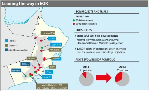
section. Figure 1.7 summarizes the types of EOR projects implemented, under trials and the
portfolio. From this figure is noticeable that the steam is the most successful EOR method
compared to others.
10
Figure 1.7 EOR Projects (successful, pilots, and the portfolio) in Oman Source: Petroleum Development Oman, oil & gas review.
(http://shop.theoilandgasyear.com/leading-the-way-in-enhanced-oil-recovery-map/) (2014)
1.1.4. Factors should be Taken into Account when Implementing Steam Injection in Sandstone Reservoirs in Oman
Steam injection though being successfully performed worldwide for several decades, yet there are still challenges associated with its operational mechanisms as discussed follows:
Clay minerals
Cation Exchange Capacity (CEC)
Polar components in crude oil
Condensed water from steam
Emulsion
Clay minerals are present in the reservoir rocks and also mixed with the oil as they can be
found in the produced oil, in the process plant, in the tanks, and in the pipelines as shown in
Figure 1.8. The most common clays found in sandstone reservoir are Kaolinite, Illite/mica, and
Montmorillonite (Wilson et al., 2014). It is a seldom to produce oil from the reservoir without
clay or sludge.
11
Furthermore, the reservoir formation water have divalent cations positively charged (i.e., Ca
2+, Mg
2+,Cu
2+, etc…). Also, the oil have polar components (Al Shalabi, 2014; Sheng, 2013).
The capacity of the clay to hold on to cations called the cation exchange capacity (CEC). The CEC of a clay represents the total amount of exchangeable cations that the clay can adsorb at a given pH (Bergaya et al., 2006). Due to the presence of the clay as an organic matter in the reservoir (weather it in the rocks or in the oil) it tends to be negatively charged. So, the interaction between the clay minerals, the cations in the formation water and the polar components in the oil in the reservoir, affect the reservoir properties especially the wettability.
The particles size of the clays also could affect in increasing or decreasing the CEC (Grim, 1968). Furthermore the effect of pH on the CEC of clay minerals, as it is well documented by Ma and Eggleton (1999) for the kaolinite for instance, higher the pH the higher CEC value.
The clay could be found in sandstone reservoir in different sizes. Adding to that, an emulsion can be performed in almost all oil production operations: inside the reservoir during EOR processes, well bores and well head, during transportation through the pipelines, crude storage and during petroleum processing (Kokal, 2005).
During steam injection EOR process, the hot and fresh water with low salinity that condensed from the injected steam during the EOR process acts as a water-flood with low- salinity (Terry, 2001). The steam will condense to water in oil reservoirs at 5000 ft in depth, then it is expected that water will reduce the efficiency of the steam flooding (Al Yousef et al., 2014). Also the fresh water condensed from steam is unfavorable for the reservoir which contains sensitive type of swelling clays, which could results in permeability reduction as happened in many thermal operations using steam (Bennion et al., 1992; Dodd et al., 1955). It has been reported by Gray (1966) and Neasham (1977) that clays affect the permeability of sandstone reservoirs significantly when they contact with fresh water by either swelling or clay particles migration from the pore wall.
However, Cerda et al. (1987) reported the opposite, the rate of permeability reduction could
be lowered, when the groundwater mixed with injected freshwater or steam condensed water
to displace the oil. Baker, Uwins, and Mackinnon (1993) investigated the freshwater sensitivity
in a sandstone reservoir rich in illite-smectite clay by using an environmental scanning electron
microscope (ESEM). They have observed directly the osmotic swelling and gel formation of
smectite clay in response to immersion in fresh water.
12
Figure 1.8 Examples of clays observed in the production tanks and pipelines in Oman.
13
Moreover, the pH gradient of the condensed water will decrease as a result of an increase in temperature (Aksulu et al., 2012). These changes in salinity and pH will affect the clay reaction in the reservoir as mentioned earlier.
Moreover, an emulsion is usually formed in the reservoir in the existence of clay during steam injection process that need to be investigated to understand its rheological behaviors and viscosity. Thus, the clay minerals plays a major role in the success or failure of steam flooding EOR process, when it reacts with reservoir components. There are also possibilities that some type of clay minerals can be used to improve the mobility control especially in heterogeneous reservoir formation containing viscous residual oils (Somerton and Radke, 1983).
The main focus of this research is to study the effects of the clay minerals on the characterizations of the emulsion formed during steam injection process in Omani sandstone reservoirs producing highly clay content. Standing from the point that the condensed water from the steam act as a LSW flooding, a core flooding experiment using LSW-flooding as a tertiary oil recovery method after re-injecting the reservoir formation water was used to understand the mechanism and prove the effect of the clay on the oil recovery and wettability alteration.
1.1.5. Previous Research Studies done on the Effects of the Clay Minerals on Steam and LSW Injection Process
In theory, during steam injection, oil is produced primarily the state of water-in-oil (W/O) emulsions as a result of physical contact between the advancing fluid (condensed steam) and the oil bank. These emulsions have an effect on the rheological behavior of the heavy oil (Maneeintr et al., 2014). Generally, these emulsions are heavier than the resident crude oil (Gafonova and Yarranton, 2001). Although it is seldom to produce crude oil alone without water and fine solid particles commingled in it, it is reported that (1) the size, (2) type, and (3) the concentration of clay dictate the efficiency steam flooding (Kokal, 2005; Yan et al., 2001).
The presence of kaolinite, illite, and/or dolomite (common clay found in sandstone) in sandstone reservoirs plays a major role in the success or failure of the steam flooding process (Kantorowicz, 1986; Muggeridge et al., 2013; Somerton and Radke, 1983).
In sandstone reservoirs, kaolinite clay minerals play a petrogenetic role that is still a matter
of debate during the steam injection process (Schembre et al., 2005). As a result of their large
14
internal surface area along with the high salinity within oil reservoirs, they tend to react rapidly and easily (Cerda, 1987). Johansen et al. (1957) showed that kaolinite adsorbs water vapor weakly. Moreover, the presence of kaolinite is reported to alter the efficiency of not only thermal methods but also non-thermal methods. In this regard, Lebedeva et al. 2010 recently proved that kaolinite contributes positively in enhancement of oil recovery (EOR) during low- salinity water flooding in the sandstone reservoir. They showed an increment of oil with a sandstone reservoir formation containing a high percentage of kaolinite. Similarly, Song and Kovscek (2015) reported that 14% additional oil was recovered by low-salinity water flooding compared to that of the formation brine.
It appears therefore that the dispersibility and migration of clay particles in reservoir sandstone, as mentioned by Tchistiakov (2000) participate actively in the efficiency of the tertiary method. Those factors lead the clay particles to detach from the solid surface of the formation and to adsorb on the oil surface, leaving behind a water-wet medium suitable for better oil recovery (Nasralla and Nasr-El-Din, 2014; Schembre et al., 2005). Also, extensive works reported that effect of both salinity and temperature on the migration of clay particles (Schembre et al., 2005). In fact, it is believed that, in low-saline medium, the rise in the temperature (perhaps during steam injection) is expected to promote (i) the stabilization of emulsions formed, (ii) the dispersion of the kaolinite particles, and (iii) the enhancement of particle mobility. Those points were addressed experimentally by Nasralla, Bataweel, and Nasr-El-Din 2011, they studied the effect of the salinity and temperature on contact angle measurements for three different brine compositions on sandstone reservoir rock. They found that low-salinity water decreased the contact angle significantly, and that would alter the wettability of the formation to more water-wet.
As mentioned earlier, since the condensed water from the steam injection is fresh with low saline, is considered as low salinity water-flooding (LSW). There are several intensive research efforts has been conducted with more ongoing on LSW applications in many fields across the world and mostly on sandstone reservoirs such as: Alaska in Canada, Pervomaiskoye and Zichebashskoe fields in Russia, Snorre field in the North Sea among others (Abbas Zeinijahromi et al., 2015; Akhmetgareev and Khisamov, 2015; McGuire et al., 2005;
Skrettingland et al., 2011).
Moreover, extensive laboratory studies have been done on LSW compared to the high saline
brine injection to produce oil, but there are a lot of discrepancy between some of those studied
15
results. Lager et al. (2006) after investigating experimentally low salinity oil recovery, made conclusions that pH is not the main reason to simulate fines migration and interfacial surface tension (IFT) reduction during LSW flooding. They further confirmed that the main reason behind additional oil recovery due to LSW flooding is as a result of the cation exchange between the brine. To mimic a practical field approach, Zhang et al. (2007) used a real reservoir core samples to investigate the performance of LSW flooding. Stated that the mechanism of improved oil recovery by LSW is related to the crude oil/brine interface, and an unclear relation between the effluent pH and oil recovery. Another prominent observation was the gradual decrease in the pH of the effluent after injecting LSW. In other experiments conducted by Bernard et al. (1967), it was established that the incremental of oil recovery by fresh-water flood compared to brine from cores containing clay was due to the presence of clay that induced in lowering the permeability and relatively high pressure drop.
Chemical mechanism of LSW flooding in sandstone reservoirs was proposed by Austad et al. (2010). They suggested that by injecting LSW, pH will increase due to Ca
2+exchange with H
+ions at clay surface. The increase in pH nigh on the clay surface causes reaction between OH
-and the adsorbed acid which promotes desorption of organic materials. Thereby, the water wetness increases hence, an eventual increase in the oil recovery.
Other research studies considered wettability alteration to be the main cause behind additional oil recovery during LSW flooding (McGuire et al., 2005; Tang and Morrow, 1999).
Zhang and Morrow (2006) observed that the rock properties is the most important factor in improved oil recovery by LSW. Patil et al. (2008) curried out core-flooding experiments to evaluate the potential of low salinity brine injection EOR for Alaska North Slope field. They observed an increase in the recovered oil as the injected brine salinity decreased. Song and Kovscek (2015) demonstrated a micromodel that allow direct visualization of the interactions between fluids/rock/clay particles for a better understanding the mechanisms of increase oil recovery in sandstone reservoir by LSW flooding due to the presence of kaolinite. They proved that an increase in oil recovery of 14% by using freshwater flooding compared to reservoir brine. They found that the increase in the recovery was attributed to the wettability alteration due to oil-wet kaolinite particles adherence to the crude oil components. Yet, in there results they have some contrast observations needed further investigations.
On the other hand, based on the latest review done on LSW by Al-shalabi and Sepehrnoori
(2015) and Sheng (2014) there are some other studied results showed higher oil recovered from
16
the high salinity water injection compared to the lower salinity and other studies showed no incremental in the recovered oil by LSW.
Indeed, it is difficult to rely on specific research results to understand how effective this process is and the mechanism behind it. This is due to the factors associated together to success this process which are often dependent on the type of the field, crude oil, reservoir water, temperature and clay type presence in the field Doust et al. (2009) and Zhang et al. (2007).
Hence, the motivation to experimentally observe and study the effect of clay on low saline water flooding or steam injection applicable to a real field experience.
Moreover, the candidate reservoir has a high clay content (which tends be the case in Oman), the emulsions thence formed reported to affect the wettability of the formation significantly and to lower the production (Al Hadabi et al., 2016). It is therefore imperative to investigate, least to understand, the effects of the presence of fine particles on this type of production scheme.
1.1.6. Wettability
The wettability in the reservoir refers to the state of the rock and the fluid in the reservoir, whether the reservoir is oil-wet or mixed/intermediate or water-wet. The distribution of a fluid in the porous media is a function of wettability. Reservoir rock wettability, currently is one of the greatest unsolved problems in the petroleum industry (Tarek, 2010). The wettability is an important factor affecting the oil recovery (the project economy), thence the factors affecting the wettability must be considered prior implementing any EOR method (Abdallah et al., 2007).
A lot of factors that affecting the reservoir wettability including the crude oil and brine composition, temperature, pH, salinity, reservoir rock properties, fine particles and clay mineral type in the reservoir (Buckley, 1996; Schembre and Kovscek, 2005).
There are several ways to evaluate the wettability; one of them is the contact angle
measurement. The reservoir is said to be: (1) water wet, when the contact angle θ between the
rock and water is less than 90°, (2) intermediate wettability case the contact angle would exist
at 90°, (3) oil wet occurs when the contact angle greater than 90° (Anderson, 1988). As shown
in Figure 1.9.
17
Figure 1.9 Wettability evaluation by contact angle measurement.
Source: (http://perminc.com/resources/fundamentals-of-fluid-flow-in-porous-media/chapter- 2-the-porous-medium/multi-phase-saturated-rock-properties/wettability)
Another method for measuring the wettability of a system is the relative permeability curves
(Anderson, 1988). The most three differences between the oil-wet and water-wet that are
generally observed: (1) the intersection point of the two curves (the water saturation at which
oil and water permeabilities are equal) is generally greater than 50 % for the water-wet cores
and less than 50 % for oil – wet ones, (2) Connate water saturations are usually greater than
20 % PV in water-wet rock and less than 10 % PV in oil – wet rock, (3) the relative permeability
to water at maximum water saturation is generally less than 30% in water -wet rock and
approximately greater than 50 % for oil-wet as shown in Figure 1.10. There are exceptions to
the second general rule stated in that the connate water saturation is higher for a water – wet
rock than the oil – wet one as stated by Raza et al. (1968).
18
Figure 1.10 Oil and water relative permeability curves for water-wet and oil-wet.
Source: (Grattoni et al., 2002)
The water-flooding - similarly steam injection – is more efficient in water-wet reservoir rock than oil-wet rocks because less water needed to be injected to produce the same amount of oil (Anderson, 1987a). Jackson et al. (2002) during their work done using reservoir scale simulation to investigate the reservoir wettability variation during water-flooding, suggested that the recovery predictions is impacted strongly by the relative permeability curves which represent the reservoir wettability. The relative permeability and wettability relation was also addressed by Donaldson et al. (1969) and Owen and Archer (1971). The wetting condition of the reservoir can be directly predicted by obtaining the relative permeability relationships during water-flooding.
The contact angle technique was used to characterize the reservoir wettability (Mittal, 2009;
Yuan and Lee, 2013). Buckley (1996) investigated the wettability alteration due the
interactions between crude oil/brine/rock my means of contact angle at different pH. The effect
of contact on drainage and imbibition process to understand the relation between the wettability
alteration and its effect oil recovery was determined by Ma et al. (1996) and Morrow (1990).
19
Nasralla et al. (2011) used the contact angle measurements to prove the wettability alteration by low salinity water.
1.2. Research Outline
1.2.1. Effect of Kaolinite on Characterization of Water-in-Oil Emulsion Formed by Steam Injection during Tertiary Oil Recovery in Heavy Oil Omani Sandstone Reservoir
As mentioned above, an emulsion can be performed in almost all oil production operations and in the reservoir during steam injection EOR process as well. Clay is presented in oil in the Omani sandstone reservoirs and that can be observed in the produced oil after centrifuged.
Thus, we decided to study the effect of the clay on the characteristics of the emulsion formed during steam injection into heavy oil. The rheological behavior of the emulsion formed during steam injection in the existence of clay and the mechanisms of the clay affect in the emulsion viscosity and reservoir wettability are considered as follows:
(i) Emulsion viscosity and it’s rheological behavior: In thermal recovery process, the heavy oil viscosity reduction mainly contributes to the incremental oil recovery (Lake, 1989). In fact, during the thermal EOR process by steam injection, an emulsion will be formed inevitability (Terry, 2001). The clay minerals are existence in the reservoir oil.
The preset research was done to a subjected heavy oil sandstone reservoir field in Oman and the kaolinite clay mineral was found to be the major clay present in the collected sludge sample. Therefore, it is necessary to understand the formed emulsion viscosity with respect to the clay type present in the targeted reservoir. It is necessary to have a good understanding of this complex petroleum emulsions with this active clay minerals for controlling and improving the production process at all stages (Maneeintr et al., 2010).
(ii) Wettability alteration: Wettability alteration also occurs when clay minerals are exist in the solution. That could happen by lowering the salinity and increasing the temperature of the solution. Nasralla, et al. (2011) indicated a change in the wettability to be more water-wet at low salinity and high temperature in sandstone reservoir rock.
The steam condescend water has low salinity and high temperature; therefore it is
20
expected to alter the wettability of the sandstone reservoir in the presence of clay minerals. For this purpose, the wettability of W/O emulsions was investigated by the mean of contact angle measurements.
1.2.2. The Effects of Kaolinite Fine Particles in Sandstone Reservoir on Omani Intermediate Oil Recovery by LSW
Since the condensed steam water is fresh with low salinity, this work is directly link to the low salinity water-flooding (LSW). To prove the first experiment results in a more practical reservoir condition, the core-flooding experiment was conducted to duplicate a subjected intermediate Omani oil reservoir field that produced high amount of clay minerals (mainly kaolinite). To understand the effect of the kaolinite in altering the reservoir wettability and its mechanism in contacting with fresh water this work are considered the following:
(i) Oil recovery: The oil recovery was compared for the three reservoir conditions: (1) the presence of the kaolinite in the reservoir grains, (2) the presence of the kaolinite mixed with the oil, and to have better understanding on the effect of the kaolinite, this two cases was compared with the third case: (3) the reservoir without kaolinite.
(ii) Wettability alteration: The effect of kaolinite on wettability alteration during low salinity water-flooding on Omani intermediate oil sandstone reservoir is examined by obtaining the relative permeability curves from the three core-flooding experiments and how it attribute to the oil recovery.
(iii) Chemical mechanism: To have a better understanding on the mechanism and the effect of the presence of the kaolinite in contacting with fresh water, the electrical charge of the clay in the brine was measured against LSW using zeta potential technique and the adsorption of the brines ions was measured in the effluents by using inductively coupled plasma mass spectrometry (ICP-MS).
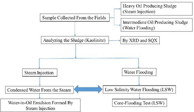
Figure 1.11 overview of the schematic flow of the present research:
21
Figure 1.11 overview of the schematic flow of the present research.
1.3. Objectives
Steam injection has been applied mostly in sandstone reservoirs in Oman. The presence of sensitive clay minerals in the sandstone reservoirs has been obviously observed. It is inevitably necessary to understand the effect of these clay minerals on the rheological behaviors and viscosity of the formed emulsion during steam injection EOR at all stages. Also, it is important to understand the effect of these clay minerals on the wettability alteration in contact with the fresh water that condensed from the steam or to be injected as LSW flooding and its mechanism.
Investigating the effect of the clay type exist in the reservoir has a critical relation in the success or failure and in improving the EOR method in a particular field.
The objectives of this research are (1) to investigate the mechanisms of the kaolinite mineral
effect on the rheological behaviors, viscosity, and wettability of the Omani heavy oil sandstone
emulsion formed by steam injection, (2) to experimentally understand the mechanism, on a
core-flooding scale experiment, of the effect of kaolinite on wettability alteration to more
water-wet through injecting fresh water as a tertiary oil recovery mode.
22
CHAPTER 2 Analysis of Oil Sludge Produced from Omani Sandstone Reservoirs
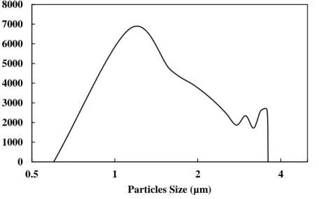
Sludge is produced immersed in oil, and is found clearly in dehydration process tanks at oil treatment plants. Figure 2.1 shows separated of sludge particles from Omani heavy oil sample with a centrifugal separator at a constant rate 4000 rpm for 24 h. Then the sediment materials was dried overnight at 160 °C to ensure a complete removal of oil. The distribution of the particles size measurement ranges from 0.6 to 3 µm as shown in Figure 2.2.
Figure 2.1 Sludge particles separated from Omani heavy oil sample with a centrifugal separator.
Figure 2.2 Distribution of particles size separated from the oil sample measurement.
Figure 2.3 shows a schematic diagram of the collected oily sludge from the bottom of the skimming tank. The sludge samples were taken from a skimming tank of a sandstone oil fields
0 1000 2000 3000 4000 5000 6000 7000 8000
0.5 1 2 4
Particles Size (µm)
23
produced by water-flooding and steam injection EOR in Oman during opening the tank for a yearly maintenance. Due to the difficulty in separating the oil from the mineral sands, for this purpose, the distilled-extraction Soxhlet method was used to have clean sand.
Figure 2.3 Sludge sample taken from skimming tank of a sandstone oil filed produced by steam injection EOR and water-flooding in Oman.
Figure 2.4 Distilled-extraction Soxhlet method used to separate the oil from the mineral sands
and a picture shows the dried separated sand.
24
The oily sludge was placed in a soxhlet and 100 ml of the toluene/methanol solvents of 50%/50% (vol/vol) – provided by Junsei chemical company Japan – were evaporated by a heater at 60 °C. The evaporated solvents were condensed by a reflux condenser to flow through the oily sludge sample removing the fluids in place as shown in Figure 2.4. Then the mineral sands were dried for 2 hours at 110 °C to ensure a complete removal of liquids as shown in the same figure. Understanding effects of the clay sludge containing in the produced oil is important to operate an enhanced oil recovery process using steam injection (Steam EOR), water-flooding, and any EOR method as well.
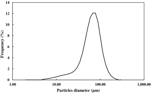
The distribution particles size measurement of the solid particles separated from the sampled oil sludge, measured by a laser particle size distribution analyzer (Horiba, model LA-920). The solid particle sizes are distributed from 5 to 200 μm with an average value of 64μm as Figure 2.5 shows.
Figure 2.5 Distribution particles size measurement of the solid particles separated from the sampled oil sludge.
We expect that this is not the right size of the particles that presented originally in the reservoir for certain reasons: the big fluctuations in their measured particle sizes that begin from about 5μm then jumped to 60μm and ends with 200μm, logically if that range of particles size flow through the pipeline all the way to the tank it might cause a plugging, and compare it with the fine sands separated from the oil sludge as was shown in Figure 2.2 it was confirmed that the measured range of the particles in the oil sludge was much bigger than expected one
0 2 4 6 8 10 12 14
1.00 10.00 100.00 1,000.00
Frequency (%)
Particles diameter (µm)
25
due to their aggregation in the skimming tank by the cations from the formation water during time that stayed in the tank. Furthermore, flocculation of mineral sands in the oil sludge can be observed in the image taken by a scanning electron microscope (SEM) as shown in Figure 2.6.
Figure 2.6 SEM image of the fine sands particles separated from the Omani oil sludge.
2.1. Sludge Sample Analysis by (XRD) and (SQX)
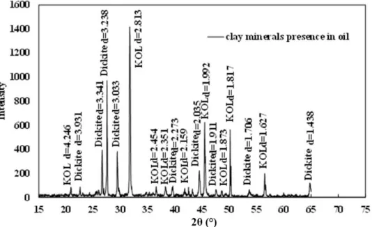
Prior to carrying out the experiments, X-ray diffraction (XRD) test was done to identify minerals contained in the collected sludge. The XRD result for the sludge in Omani heavy oil are shown in Figure 2.7.
Figure 2.7 XRD diffraction for the sludge in Omani heavy oil.
26
Figure 2.8 shows the XRD results for the sludgy oil collected from the skimming tank of a water-flooding Omani sandstone reservoir. The XRD results obviously show that the kaolinite is the main mineral (almost 70%) constituent the oily sludge sample produced from the subjected Omani oil field by steam flooding and water-flooding. The presence of dickite was expected - especially in the depth of oil fields basins - due to the transformation of kaolinite to dickite in sandstone reservoirs depth resulting from geochemical and thermodynamical reactions. Beaufort (1998), investigated and proved the transformation of kaolinite-to-dickite in sandstone reservoirs by using Scanning Electron Microscope (SEM), XRD, Fourier Transform Infrared Spectroscopy (FTIR) and Differential Thermal Analysis (DTA). Also Wilson et al. (2014) evoked the possibility of fine migrations followed by kaolinite dissolution.
Ultimately, kaolinite is transformed into “solid” phase, presumably dickite. Given the operational conditions in that oilfield from which the sample was collected, one may thus validate this thought. Quartz are often found within samples collected from any sandstone reservoir and it is one of the reasons that makes the analyses of only kaolinite by XRD to be ambiguous (Beaufort, 1998).
Figure 2.8 XRD diffraction for the sludge sample taken from a dehydration tank of a sandstone oil field in Oman.
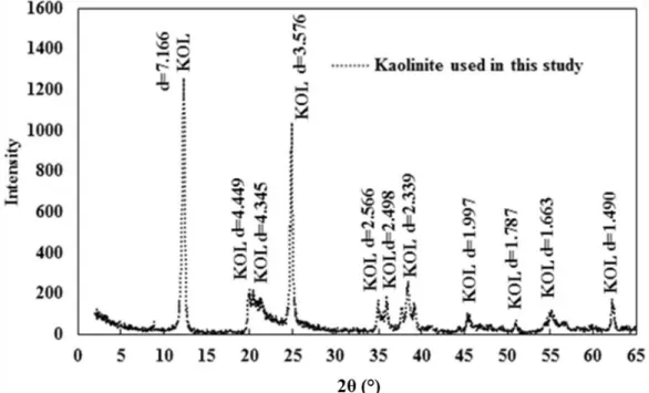
Also, if the spectrum of oil sludge samples was to be compared to that of pure kaolinite
(Figure 2.9), a slight shift appeared that could be attributed to the heat and/or water, oil, and
depth in the reservoir. This is to say that the presence of the oil and the conditions existing
within the formation act upon the properties of kaolinite perhaps by enhancing their colloidal
27
properties. The pure kaolinite clays was used for the experimental investigations instead of the actual formation sludge. This was performed primarily to avoid the chemical complexity of actual sludge and also because kaolinite is reported to be the major component of the sludge.
The XRD analysis was followed by advanced semi-quantitative X-ray analysis (SQX) program to know the multiple elements within the sample and compare it with the kaolinite used in the experiment as shown in Table 2.1.
The result confirm and support the XRD result that the kaolinite is the major clay mineral in the sampled oil sludge and have almost the same chemical compositions of the kaolinite- particles slurry.
Figure 2.9 XRD spectra pattern of pure kaolinite powder and slurry.
Table 2.1 Representative chemical composition of the oil sludge sample from Omani sandstone reservoir and the pure kaolinite-particles slurry used in this experiment
aSiO
2Al
2O
3Fe
2O
3TiO
2CaO MgO Na
2O K
2O SO
3A 66.16 10.01 8.52 1.02 3.70 0.872 1.38 3.98 3.02 B 49.20 35.70 0.82 0.51 0.14 0.15 0.09 0.50 -
a
A: oil sludge sample from Omani sandstone reservoir, B: pure kaolinite; units are in mass
(%)
28