Title Potential Analysis of Small Hydropower Generation UsingIrrigation Facilities( 本文(Fulltext) )
Author(s) WANG FENGLAN
Report No.(Doctoral Degree) 博士(農学) 甲第725号 Issue Date 2020-03-13 Type 博士論文 Version ETD URL http://hdl.handle.net/20.500.12099/79392 ※この資料の著作権は、各資料の著者・学協会・出版社等に帰属します。
Potential Analysis of Small Hydropower Generation
Using Irrigation Facilities
(農業水利施設を利用した小水力発電の潜在力評価)
2019
The United Graduate School of Agricultural Science, Gifu University
Science of Biological Environment
(Gifu University)
WANG FENGLAN
Potential Analysis of Small Hydropower Generation
Using Irrigation Facilities
(農業水利施設を利用した小水力発電の潜在力評価)
i
SUMMARY
Since the occurrence of the accident at the Fukushima Daiichi Nuclear Power Plant in 2011, the Japanese government has emphasized the further development of renewable energy, such as solar, wind power, thermal power, small hydropower and biomass and etc. Among them, there is a growing interest in small hydropower generation (hereafter called SHP in this paper) that is small in output but technically practical. It has several significant advantageous compared to other renewable energy such as it can use the various water resource (river water, irrigation water, drainage water and etc.); expense of maintenance management is low. Furthermore, water resource is abundant and geography is steep in Japan, which supports the development of small hydropower generation.
Small hydropower generation using irrigation facilities has been attracting attention as an energy infrastructure that can save initial investment cost due to its long total length and many unused existing heads. In addition, it is expected that at headworks, it has great potential power generation due to its’ permanent flow rate data through the year and existing heads.
Potential analysis of small hydropower generation using irrigation facilities are carried out from the two following topics:
1. Potential analysis of small hydropower generation using irrigation facilities - Case study of Meiji-yousui Land Improvement District-
2. Potential for and feasibility of small hydropower generation at headworks in Japan In the first research, the potential power generation was examined at agricultural irrigation facilities from the headwork to the Sawatarif main irrigation canal managed by
ii
Meiji-yousui Land Improvement District to evaluate the feasibility of SHP as a candidate place. The five research place were selected to evaluate the SHP with using more than sixteen years’ data which recorded by the Meiji-yousui Land Improvement District, namely, Meiji-yousui headwork, industrial division work, three check stands (Akamatsu, Nihongi and Higashiyamada check stands). In addition, two mud drainage works (Sawatari and Matsushita) are raised to have possibility of potential power generation. The difference between the upstream and downstream water levels at the headworks was assumed as an effective head. As a results, the maximum output, the average annual power generation, and the maximum monthly power generation were the largest at the headwork and the industrial water diversion work and the check stands followed it in this order. The power generation at the industrial water division work showed a seasonal gap between irrigation/non-irrigation periods/non irrigation periods but a more stable amount every year than other agricultural irrigation facilities. Year- round water flow in the Mud drainage works, which are flashing water a few times in a year, are expected to utilize their potential for the hydropower and to improve water environment in drainage canals and downstream river reaches.
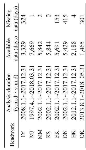
In the second research, focusing on the overflow discharge at eight representative headworks located in Aichi and Gifu Prefectures, namely, Inuyama (IY), Meiji-yousui(MJ), Muromatsubara(MM), Kansakawa(KS), Furikusa(FK), Onyu(ON), Hosokawa(HK) and Okajima(OK) headwork, the feasibility of SHP generation at headworks is examined by analyzing the power generation potential and the characteristics of seasonal fluctuations. The difference between the upstream and downstream water levels and the weir heights at the headworks was assumed as an effective head. Overflow discharge of eight headworks had been recorded more than five
iii
years by the Land Improvement District to evaluate the potential of power generation. The maximum power output for the SHP was determined under the discharge utilization factor of 60%, and the annual power generation and the monthly power generation were calculated. As a result, firstly, the excess probabilities of overflow discharge were from 18.2% to 32.0% and the intake discharge was from 25.6% to 57.2%. This means that power generation using the overflow discharge is more stable than that using the intake discharge. Secondly, the maximum power output was obtained from 43 kW to 2002 kW, which shows the great potential for power generation at these eight headworks. However, they showed the fluctuations in both the annual and the monthly power generation, and the fluctuation in the annual power generation is smaller than that in the monthly power generation. The monthly fluctuation of power generation is mainly influenced by two factors, namely, the amount of water intake during the irrigation period and the seasonal rainfall fluctuation. These factors cause the following two patterns of monthly power generation: the first pattern shows power generation that is smaller during the irrigation period when a large amount of agricultural water is taken. The second pattern shows power generation that is larger in the summer season because there is indirect water intake in the beneficiary areas and the precipitation rate is higher in summer.
iv LIST OF CONTENTS P a g e SUMMARY………ⅰ LIST OF CONTENTS………ⅳ LIST OF TABLES………. ⅵ LIST OF FIGURES………ⅶ Ⅰ. INTRODUTION 1 1.1 Background 1 1.2 Research objectives 3
Ⅱ. MATERIALS AND METHODS 4
2.1 Materials 4
2.1.1 Outline of Meiji-yousui 4
2.1.2 Outline of eight research headworks 7
2.2 Method 11
2.2.1 Available data and effective head obtained 11
2.2.2 Calculation method 13
v
3.1 Potential analysis of small hydropower generation using Irrigation facilities – Case study of Meiji-yousui Land
Improvement District- 14
3.1.1 Overflow discharge from the MJ to the downstream of the Yahagi River 14
3.1.2 Unused head existing in main line waterway (Industrial Division work) 19
3.1.3 Delivery management water at Akamatsu check stands 23
3.1.4 Delivery management water at Nihongi and Higashiyamada 29
check stands 3.1.5 The generation potential at mud drainage work 33
3.1.6 The comparison of research sites 34
3.1.7 Conclusion 37
3.2 Potential and feasibility for small hydropower generation at headworks in Japan 39
3.2.1 Daily overflow discharge and excess probability 39
3.2.2 Maximum power output with discharge utilization factor of 60% 41
3.2.3 Annual and monthly power generation under the discharge utilization factor of 60% 46
3.2.4 Conclusion 50
Ⅳ. CONCLUTION 51
ACKNOWLEDGEMENT 53
vi
LIST OF TABLE
Table2.1 Outline of test headworks 10 Table 2.2 Available data on amounts of overflow discharge
from headworks 12 Table 3.1 Structure parameters, plan of irrigation management and parameters of hydropower generation estimated
on the irrigation plan at each check stand 27 Table 3.2 Maximum power output and annual and monthly power
generation at each potential power plant site 36 Table 3.3 Amounts of overflow discharge at test headworks 41 Table 3.4 Maximum power output (kW) with discharge utilization
factor of 60% 45 Table 3.5 Excess probabilities (%) of overflow discharge and intake
discharge with discharge utilization of 60% 45 Table 3.6 Maximum power output and annual and monthly power generation
vii
LIST OF FIGURES
Fig. 2.1 Irrigation facilities and water flow in Meiji-yousui 6 Fig. 2.2 Locations of test headworks 9 Fig. 3.1 Distribution curve of overflow discharge at the headwork 17 Fig. 3.2 Estimated maximum power output and discharge
utilization ratio at the MJ 17 Fig. 3.3 Annual power generation at the headwork 18 Fig. 3.4 Monthly power generation at the headwork (Solid line: mean value, dotted line: 25 and 75 percentiles) 18 Fig.3.5 Maximum power output and discharge utilization ratio
at the industrial division work 21 Fig. 3.6 Annual power generation at the industrial water division work 22 Fig. 3.7 Monthly power generation at the industrial water division work
(Solid line: mean value, dotted line: 25 and 75 percentiles) 22 Fig. 3.8 Estimated maximum power output and utilization ratio
at the Akamatsu check stand 28 Fig. 3.9 Annual power generation at the Akamatsu check stand 28 Fig. 3.10 Monthly power generation at the Akamatsu check stand
(black line: mean value, black dot: 25 and 75 percentiles,
grey dot: estimation based on the irrigation plan) 29 Fig. 3.11 Estimated maximum power output and utilization ratio
at the Nihongi check stand 30 Fig. 3.12 Annual power generation at the Nihongi check stand 31 Fig. 3.13 Monthly power generation at the Nihongi check stand
viii
(black line: mean value, black dot: 25 and 75 percentiles) 31
Fig. 3.14 Estimated maximum power output and utilization ratio at the Higashiyamada check Stand 32
Fig.3.15 Annual power generation at the Higashiyamada check stand 32
Fig.3.16 Monthly power generation at the Higashiyamada check stand (black line: mean value, black dot: 25 and 75 percentiles) 33
Fig. 3.17 Distribution curves of amounts of overflow discharge at headworks 40
Fig. 3.18 Excess probability and discharge utilization factor 42
Fig. 3.19 Excess probability and maximum power output ratio 43
1
I. INTRODUCTION 1.1 Background
Since the occurrence of the accident at the Fukushima Daiichi Nuclear Power Plant in 2011, the Japanese government has emphasized the further development of renewable energy, such as solar, wind power, thermal power, small hydropower and biomass, through the introduction of a feed-in tariff (FIT). FIT is a policy designed to accelerate investments in renewable energy technologies by offering long-term contracts to renewable energy producers (Huenteler et al., 2012; Goto et al., 2012). As an alternative source of energy, attention is increasingly being focused on small-scale hydropower generation.
There is no clear official definition of the small hydropower facilities existing in each country. However, SHP is generally known around the world as the maximum power output of 10 MW (Paish, 2002; Bockman et al., 2008). SHP is regarded in Japan as the power output from 1 MW to 10 MW (Ministry of the Environment, 2003), and especially, according to the National Small Hydropower Promotion Council (Japanese Water Agency, 2019), the power output of less than 1 MW is recognized as new energy which is supported by the measure of Renewables Portfolio Standard. The purpose of these measures are to promote the use of new energy through the obligatory utilization of a certain amount of electricity obtained by new energy by power generation industries. Here, the global definition for the most widely accepted value of power output up to 10 MW in the world is used; it is called small hydropower generation in this paper.
Small hydropower generation using agricultural irrigation facilities has been attracting attention for its availability as an energy infrastructure that can reduce initial investment due to its long total length and many unused heads. In particular, Aichi
2
Prefecture has large-scale irrigation facilities represented by Meiji-yousui, Toyokawa Yousui, and Aichi Yousui, and the extension of agricultural waterway is 2,488 km, ranking third in Japan following after Hokkaido and Niigata Prefectures (Rural Promotion Bureau, Ministry of Agriculture, Forestry and Fisheries, 2016), the density of waterways to farmland is the highest in the country. In addition, it was reported that Aichi Prefecture was ranked first in the power generation potential with 78MW using agricultural irrigation facilities. (Ministry of the Environment, 2011)
On the other hands, in Japan, 95% of the water used in agriculture comes from rivers (Okuda, 2010). However, it is difficult to control the amount of water intake under the natural conditions of rivers due to the large changes in the river water levels accompanying changes in the flow rate because Japanese rivers have the characteristics of steep gradients and short lengths (Ueda et al., 2013). Therefore, by installing a headwork across a river, the stable water level necessary for water intake is secured, and using this gravitational potential energy, the water demand is supplied to the downstream for the entire beneficiary area. Since Japan's topography is steep, many drop works, torrent works, etc. were constructed in the agricultural waterways, and SHP has been actively introduced by utilizing these existing works. This kind of power generation is called the agricultural water-dependent type of power generation. It has many advantages for power generation as it is carried out within the range of agricultural water, so it does not require the acquisition of new water rights for power generation, and it generates power in the existing water supply facilities which save construction and other costs. However, because the range in fluctuation of the flow rate is large during irrigation and non-irrigation periods with this type of power generation, it has low power generation efficiency which has become a problem. On the other hand, at the headwork, besides the
3
intake water, in order to maintain the river water level necessary for water intake, surplus water (hereinafter called overflow discharge in this paper) will flow downstream by overflowing the spillway. Thus, headworks can be considered as candidate sites for high-quality power generation that can secure a certain flow rate throughout the year and a stable water level. However, only two SHP facilities have been installed at headworks in Japan to date (Miyai et al., 2018), even though there are 8,250 headworks in rivers (Ministry of Agriculture, Forestry and Fishers, 2008). The two facilities are the Shintawaraizeki Power Plant in Okayama Prefecture, with a capacity of 2,400 kW, and the Gojyo Power Plant in Niigata Prefecture, with a capacity of 1,100 kW; they utilize the effective head and the downstream discharge (Miyai et al., 2018). The reason for the small number of SHP installations is that a certain procedure must be followed for obtaining water rights for power generation, permission must be obtained from the river manager to construct the SHP facility in the river, and the river maintenance flow rate must be considered in the area of reduced water in the actual planning. In recent years, in order to promote SHP facilities, the procedure for obtaining water rights for power generation, based on the non-agricultural water-dependent type of power generation, has been simplified (Ministry of Agriculture, Forestry and Fishers, 2014), and the active introduction of small hydropower generation at more and more headworks can be expected in the future.
There are two researches that have been conducted to evaluate the feasibility of SHP by analyzing the power generation potential and characteristics of research sites.
1.2 Research objectives
4
have been carried out with the following objectives:
1) In the first research, to analyze the power generation potential and characteristics of research places using agricultural irrigation facilities namely, Meiji-yousui headwork, industruarl water division work, three check stands (Akamatsu, Nihongi, Higashiyamada) and mud drainage works (Sawatari and Matsushita) which are managed by the Meiji-yousui Land Improvement District to evaluate the feasibility of SHP.
2) In the second research, focusing on the overflow discharge at eight representative headworks located in Aichi and Gifu Prefectures, the feasibility of SHP generation at headworks is examined by analyzing the power generation potential and the characteristics of seasonal fluctuations. Eight research headworks are IY, MJ, MM, KS, FK, ON, HK and OK.
ⅡMATERIALS AND METHOD
2.1 Materials
2.1.1 Outline of Meiji-yousui
The water of Meiji-yousui is taken from the Yahagi River, which flows in the middle area of Aichi Prefecture, and supplies irrigation water for approximately 6,000 ha of paddy fields across 8 cities in Western Mikawa, centering on Anjo City. The facilities managed by the Meiji-yousui Land Improvement District are the waterways with a total length of about 400 km (the main canal and the branch canal) (Fig. 2.1). The Meiji-yousui main canal, which takes water from the Meiji-yousui headwork, is diverted to the western canal at the Hirokute water control gate which is 7.5 km from the Meiji-yousui headwork. Furthermore, at the Chuto division work which is located at the Sawatarif the Meiji-yousui main canal, middle canal and eastern canal were diverted. In the upstream side of
5
the Hitokute water control gate, the agricultural water is sent by the open canal, utilizing the steep waterway gradient. In this section (from Meiji-yousui headwork to Hirokute water control gate), there are fourteen direct water division places and one water division that is online monitored by the central management station. There are two places where water is controlled and monitored. On the other hand, in the downstream from the Hirokute water control gate, the water is sent by a pipe channel to the Sawatarif agricultural area. In this section, there are fourteen direct water division, five water division under monitoring, and fifteen water division under monitoring control.
In this way, Meiji-yousui sends and distributes irrigation water to farmland through a long waterway after taking water from Meiji-yousui headwork. However, because there are no intermediate storage facilities such as a regulating pond in the main waterway due to topographical restrictions, various forms of management water are occurred when the water is taken or diverted.
6
Fig. 2.1 Irrigation facilities and water flow in Meiji-yousui
Chuto division work
Industrial division work
Nihongi
division work division workAkamatsu
Yobaiike check stand Higashiyamada check stand
right bank water intake mounth Matsushita mud drainage work Hirokute control gate Meiji Yousui headwork Sawatari mud drainage work
Yahagi River Western canal Eastern canal Middle canal Industrial water M iddl e ca na l Ue kur a di rty w ate r di vi sion Shi ndo w ate r di vi sion Ka gur a san w ate r di vi sion
Isami check stand
Hir oku te w ate r di vi sion G ens en w ate rdi vi sion Ea ste rn ca na l Saihananoki check stand O ida di rty w ate r di vi sion N ishi toku w ate r di vi sion Saijo check stand
7
2.1.2 Outline of eight research headworks
In this research, the daily overflow discharge of eight headworks located in Gifu and Aichi Prefectures (Fig.2.2) has been recorded for more than five years (Table 2.2) to evaluate the power generation potential.
Inuyama headwork
IY is located about 59 km upstream from the mouth of the Kiso River in Aichi Prefecture. It takes water (max: 51.06 m3/s) from the Kiso River to the Kotsu, Hashima
and Miyata irrigation districts (total 9,353 ha). In the upstream of IY, there are four dams for power generation, namely, Imawatari, Kaneyama, Kawabe and Kamiaso Dams. Furthermore, there are two water intake mouths in the downstream of IY in the Kiso River, the Asahi and Bisai water intake mouths for tap water (6.58 m³/s), and Kisogawa ouzeki weir for agricultural, domestic and industrial water use (41.83 m³/s).
Meiji-yousui headwork
MJ is located about 35 km upstream from the mouth of the Yahagi River in Aichi Prefecture. It takes water (max: 42.19 m3/s) from the Yahagi River to the Meiji-yousui
district for agricultural, domestic and industrial use. The water of the Meiji-yousui is controlled by the discharge from Koshido Dam located 7 km upstream of MJ. No individual or entity is responsible for using the amount of water being discharged from MJ to the downstream of the Yahagi River; and therefore, it is possible for MJ to take the maximum amount of water as is possible within the limits of the government’s rules on water rights.
8
Toyokawa yousui district: Muromatsubara, Kansakawa, Onyu and Furikusa headworks
Five headworks were constructed for the purpose of supplying water to the Toyokawa yousui district in Aichi Prefecture. The water of the Toyokawa yousui district is basically sourced from Ure and Oshima Dams. The water released from these dams flows to the upstream of Ohno headwork (OH). Furthermore, KS takes water from the Toyokawa
River to the upstream of OH by the Kansakawa conduit. The water demand of the Toyokawa yousui district is taken by OH for agricultural, domestic and industrial use via two waterways, namely, eastern and western canals. Furthermore, in the downstream of OH in the Toyokawa River, there is MM which supplies water to Toyohashi City and its surrounding area via the Muro and Matsubara Canals.
The catchment area for Ure Dam is too small to supply the water demand of the Toyokawa yousui district. Therefore, the water is led to the dam from the branch rivers (the Onyu and Ochise Rivers) of the Tenryu River by the following two-steps. Firstly, ON takes water from the Onyu River to the upstream of FK placed in the Ochise River, and secondly, FK takes water from the Ochise River to the upstream of Ure Dam.
As mentioned above, Ure Dam, Oshima Dam and KS are integrated to supply water to the upstream of OH, and almost all the water is taken by OH to meet the demand for water in the Toyokawa yousui district, for which very little overflow discharge occurs, including fishways to the downstream of OH. This is the reason why OH was not selected for the analysis of power generation in this research.
Hosokawa headwork
9
water (max: 18.71 m3/s) for agricultural, domestic and industrial use. Habu Dam, 25 km
from HK in the upstream of the Tomoe River, supplies irrigation water for the west Mikawa region.
Okajima headwork
OK is located about 60 km upstream from the mouth of the Ibi River in Gifu
Prefecture, and takes water (max: 21.71 m3/s) from the Ibi River to the Seino irrigation
district (5,332 ha). Yokoyama Dam is located 20 km upstream of OK in the Ibi River; it discharges the required amount of water for the Seino irrigation district.
10
NL
EL
Inu
ya
m
a
(I
Y)
35.39
136.94
4.5
420
51
.06
M
eij
i yo
us
ui
(M
J)
35.05
137.18
5.6
167
42
.19
M
ur
om
at
sub
ar
a
(M
M
)
34.88
137.47
3.3
196
8.
00
Ka
ns
aka
w
a
(K
S)
34.97
137.55
3.9
58
15
.00
Fur
iku
sa
(F
K)
35.08
137.68
2.5
34
15
.00
O
ny
u(
O
N
)
35.14
137.70
3.8
30
5.
00
Hos
ok
aw
a
(H
K)
35.03
137.18
2.1
64
18
.71
O
ka
jim
a
(O
K)
35.48
136.57
3.3
162
21
.70
Loc
at
ion
(°
)
W
eir
he
igh
t(m
)
W
eir
leng
th(
m
)
M
ax.
int
ake
(m
³/s
)
He
adw
or
k
Tab
le2
.1
O
ut
lin
e
of
te
st
hea
dw
or
ks
11
2.2 Method
2.2.1 Available data and effective head obtained
In the first research, analysis of power generation potential was carried out using overflow discharge to the downstream of the Yahagi River at the Meiji-yousui headwork, unused drop existing in the main waterway, delivery management water at check stands and overflow discharge water from the mud drainage works at the Hirokute water control gate and Chuto division work based on the hydraulic data managed by the Meiji-yousui Land Improvement. For the calculation of the power generation potential, the total flow rate for 7,305 days (20 years) from April 1st, 1997 to March 31th, 2017 (recorded at 9:00 am, m3 / s) was used. The effective head was obtained from the difference between upper
and lower water levels. The effective head is in order of Meiji-yousui headwork (5.6m), Industrial water division work (5.45m), Akamatsu check stand (7.5m), Nihongi check stand (4.21m), Higashiyamada check stand (6.38m).
In the second research, the effective head of IY and MJ was assumed to be the difference between the upper and lower water levels, namely, 5.8 m and 5.6 m, respectively. For the other six headworks (MM, KS, FK, ON, HK and OK), the weir height was used as the effective head (Table 2.1). For overflow discharge data of eight headworks was shown in Table 2.2.
12
He
adw
or
k
Ana
lys
is
dur
at
ion
(y.
m
.d
~y
.m
.d)
Ava
ila
bl
e
da
ta
(da
ys
)
M
iss
ing
da
ta
(da
ys
)
IY
2008.1.1~
2017.12.31
3,329
324
MJ
1997.4.1~
2018.03.31
7,669
1
MM
2002.1.1~
2017.12.31
5,842
2
KS
2002.1.1~
2017.12.31
5,844
0
FK
2002.1.1~
2017.12.31
5,691
153
ON
2002.1.1~
2017.12.31
5,429
415
HK
2012.1.1~
2017.12.31
2,188
4
OK
2013.8.1~
2018. 05.
31
1,465
301
Tab
le 2.
2
Av
ai
la
bl
e d
at
a
on
am
ou
nt
s of
ov
erfl
ow
d
isc
ha
rg
e f
ro
m hea
dw
or
ks
13
2.2.2 Calculation method
At first, the discharge utilization factor (%) was assumed when the daily discharge corresponding to an excess probability of 10-90% was used as the maximum discharge for power generation. Here, “discharge utilization factor" is the index expressed as the mean actual discharge divided by maximum discharge. The “mean actual discharge” is the average daily discharge throughout the year under the upper limitation of the maximum discharge, while the “facility utilization factor” is represented by the actual power generation divided by possible power generation. The "possible power generation" means the annual amount of power generation produced under the maximum power output (kW) throughout the year, and the "actual power generation" means the amount of power generation that is produced by the actual discharge at the headwork under the limitation of the above-mentioned maximum discharge. It is obvious that the facility utilization factor increases with the decrease in the maximum power output produced by maximum discharge.
According to the nonlinear relation between the discharge and the power output, the facility utilization factor is 5% to 10% (median value: 7.5%) smaller than the discharge utilization factor (New Energy Foundation, 2013).
In formulating the power generation plan, the facility utilization factor is adopted as being from 45% to 60% (median value: 52.5%) (Ministry of Economy, Trade and Industry Agency for Natural Resources and Energy, 2005). In this analysis, the discharge utilization factor is assumed as the sum of the two median values, namely, 60% (= 52.5% + 7.5%), in order to obtain the maximum power output. The power generation is estimated using this maximum power output.
14
calculated from the following equation in both research. P=g× η × Q × H
(P: power output [kW], g: gravitational acceleration [m/s²], η: general efficiency (=0.72), Q: flow rate [m3/s] and H: effective head [m]).
The general efficiency is expressed by the product of the turbine efficiency and the generator efficiency. According to the Hydro Valley Plan Guidebook (Ministry of Economy, Trade and Industry Agency for Natural Resources and Energy, 2005), the turbine efficiency is 0.75 to 0.90 (average value: 0.825) for small and medium hydraulic turbine generators and the generator efficiency is about 0.82 to 0.93 (average value: 0.875); therefore, the general efficiency is 0.72 (= 0.825 × 0.875).
The maximum power output with the discharge utilization factor of 60% at each headwork is determined by the following two steps. Firstly, the excess probability of the overflow discharge, corresponding to the discharge utilization factor of 60%, is obtained. Secondly, the maximum power output corresponding to each excess probability of discharge utilization factor (60%) is obtained.
The annual and monthly power generation at research sites were estimated using the maximum power output.
Ⅲ. RESULTS AND DISCUSSION
3.1 Potential analysis of small hydropower generation using irrigation facilities – Case study of Meiji-yousui Land Improvement District-
3.1.1 Overflow discharge from the MJ to the downstream of the Yahagi River
15
its own basin. There are four Chubu Electric Power's power generation dams (Yahagi Daini, Douzuki, Asuri, Koshido) in the section from Yahagi Dam to MJ. So, actually, the water of Meiji-yousui is secured by the discharge from the Koshido Dam and its own flow. In other words, the necessary water is reported to the Koshido Dam at 4:00 in the evening of the previous day from the management office of the MJ, and the discharge volume for the next day is determined. It is possible for MJ to take the maximum amount of water as is possible within the limits of the government’s rules on water rights. However, due to the increase in water collection between the Koshido Dam and MJ during rainfall period, and the decrease in water intake at the farmlands, the water intake at the headwork for irrigation has decreased and overflow discharge will occur. It occurs throughout the year, although this discharge has a big seasonal fluctuation. And the both the flow rate and the effective head (the weir water level of headwork: 5.6m) are large, so the possibility of power generation using this overflow discharge is examined.
Fig. 3.1 expresses the relation of 20 years’ overflow discharge (m3/s) of MJ and excess
probability
.The daily overflow discharge at 9:00 am is sorted in descending order, and the number of days corresponding to the overflow discharge is divided by the number of days in 20 years (7,305 days) and expressed as a percentage. This percentage is called excess probability. From the Fig. 3.1, we can see rich water discharge (excess probability26%=95/365) is 29.1m3/s; ordinary water discharge (excess probability
50.7%=185/365) is 14.3 m3/s; low water discharge (excess probability 75.3%=275/365)
is 6.4 m3/s.
The target overflow discharge of maximum power output is transformed into excess
16
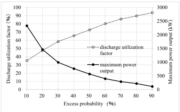
factor was obtained as shown in Fig. 3.2. The overflow discharge corresponding to the discharge utilization factor of 60% is obtained, and it becomes 23.5 m3 / s with an excess
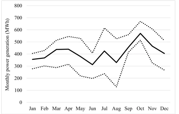
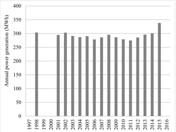
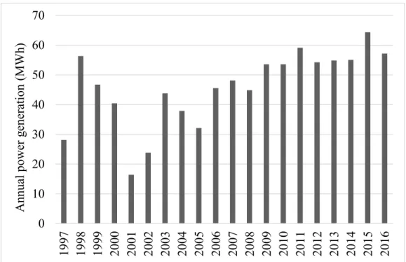
probability of 32.2%, and accordingly, the maximum power output is 941kW. Fig. 3.3 shows the annual power generation when the maximum power output is 941kW. Fig. 3.4 shows the monthly power generation (mean value, value of 25% and 75%) when the maximum power output is 941kW. By limiting the maximum power output, the annual power generation becomes from 3,190 to 6,580 MWh (average 4,944 MWh), and the fluctuation in annual power generation was also reduced. The average monthly power generation was obtained to be a minimum value of 312 MWh in June and a maximum value of 571 MWh in October, enabling relatively stable power generation of over 300 MWh/month throughout the year. On the other hand, there was a larger fluctuation in monthly power generation in irrigation period, in particular, in August, for the 25% value, it is being 39% of the average value. This becomes the obvious small values in all year round. This reflects the water savings during the irrigation season in drought years, but it also noted that electricity demand will increase simultaneously with water demand in irrigation season.
17
Fig. 3.1 Distribution curve of overflow discharge at the headwork
Fig. 3.2 Estimated maximum power output and discharge utilization ratio at the MJ 0 10 20 30 40 50 0 20 40 60 80 100 Ove rflow discha rg e(m 3 /s) Excess probability (%) 0 500 1000 1500 2000 2500 3000 0 10 20 30 40 50 60 70 80 90 100 10 20 30 40 50 60 70 80 90 Disc ha rg e uti liz ati on fa ctor (%) Excess probability (%) discharge utilization factor maximum power output Ma xim um powe r output (kW )
18
Fig. 3.3 Annual power generation at the headwork
Fig. 3.4 Monthly power generation at the headwork (Solid line: mean value, dotted line: 25 and 75 percentiles) 0 1000 2000 3000 4000 5000 6000 7000 1997 1998 1999 2000 2001 2002 2003 2004 2005 2006 2007 2008 2009 2010 2011 2012 2013 2014 2015 2016 Annua l powe r g ene ra tion (MW h) 0 100 200 300 400 500 600 700 800
Jan Feb Mar Apr May Jun Jul Aug Sep Oct Nov Dec
Mont hly powe r g ene ra tion (MW h)
19
3.1.2 Unused head existing in main waterway (industrial water division work)
Within the main waterway of the Meiji-yousui, there exist large heads at two places which are at the Hirokute water control gate and at the industrial water diversion in Middle canal. The Hirokute water control gate located at 7.5 km in the downstream from the headwork, and there is a geographical height of about 4 m in the main waterway. In 1937, a power plant with a maximum output of 230 kW (“Hirogaki Power Plant”, Hiromi-cho, Toyota City) was established using this head. It was operated for 23 years by the private person. However, it was closed after a disaster due to the Isewan Typhoon in 1959. Water turbines and generators were removed, and the power plant site was exhibited in a park. However, for rehabilitating an aged open waterway in the state-run project “Yahagi River Comprehensive Agricultural Water Conservation Project” that started in 1970, using this 4m head for constructing a pipe channel which supplies water to the end of beneficiary areas with natural pressure, it is difficult to generate electricity using this head at this stage (Tanaka, 1987).
Another unused drop is placed at industrial division work which is at 2.1km from the Chuto division work in Middle canal. This site is at the direct downstream of the industrial division work which still belong to the section of exclusive water use of agriculture. The effective head corresponds to the difference in the set water level between the Chuto division work and the Nihongi division work, and the average water level difference over the past 20 years is 5.45m (= 26.37-20.92m). Therefore, using the same calculation method as Meiji-yousui headwork, the maximum power generation output with a discharge utilization rate of 60% was determined by using the flow rate in section of exclusive water use of the agriculture and the measured data of water level difference of the past 20 years to obtain the annual power generation and average monthly power
20
generation.
From the Fig. 3.5, the maximum power output when the discharge utilization factor of 60% was 60.4kW with an excess probability of 46.3%. In addition, using this maximum power output of 60.4 kW to obtain the annual and monthly power generation. Sixteen years (the four years of 1991, 1999, 2000 and 2017 had a missing or abnormal value of more than one month, respectively, so excluded from the analysis) was used for this analysis. As a results, the annual power generation was distributed from 274MWh to 339 MWh (Fig. 3.6), and more stable power generation was expected compared to the Meiji-yousui headwork. Monthly power generation when the maximum power output of 60.4 kW is shown in Fig. 3.7. In comparison to the non-irrigation season (from October to April), the monthly power generation in irrigation season (from May to September) is four times higher as 40 MWh/month. This shows the characteristics of agricultural water-dependent type of power generation, where the fluctuation in annual power generation is small throughout the year.
21
Fig.3.5 Maximum power output and discharge utilization ratio at the industrial division work 0 20 40 60 80 100 120 140 160 0 10 20 30 40 50 60 70 80 90 100 10 20 30 40 50 60 70 80 90 Excess probability (%) discharge utilization factor
maximum power output
Disc ha rg e uti liz ati on fa ctor (% ) Ma xim um powe r output (k W)
22
Fig. 3.6 Annual power generation at the industrial water division work
Fig. 3.7 Monthly power generation at the industrial water division work (Solid line: mean value, dotted line: 25 and 75 percentiles)
0 50 100 150 200 250 300 350 400 1997 1998 1999 2000 2001 2002 2003 2004 2005 2006 2007 2008 2009 2010 2011 2012 2013 2014 2015 2016 Annua l powe r g ene ra tion (MW h) 0 10 20 30 40 50
Jan Feb Mar Apr May Jun Jul Aug Sep Oct Nov Dec
Mont hly powe r g ene ra tion (MW h)
23
3.1.3 Delivery management water at Akamatsu check stand
The main waterway of Meiji-yousui is consisted by open channels and pipeline. The upstream of Hirokute water control gate is open channel, and the downstream of it is pipelined. There are no intermediate storage facilities such as regulating ponds in the main waterway. So, in order to distribute the water for the farmlands with high accuracy, check stands which can adjust the water level, are constructed at seven water division points in the main waterway. The water demand in the beneficiary area varies depending on weather conditions and crop growth conditions, and in response to this change in water demand, the water level and water division in the pipeline will have fluctuation, accordingly, the water level in the check stand will fluctuates. The flow rate control cannot follow the transmission speed of this water level fluctuation because the upstream part is an open channel, and air is getting involved into the pipeline when the water level of the check stand is suddenly lowered. It will cause damage and water leakage of the pipe. In response to fluctuations in water demand, it is necessary to keep the water level of the check stands stable. Therefore, the water level of the check stand is managed as spillway floor height + 10cm (target water level) in the irrigation period (April 24th to October 5th) in which the fluctuation is larger. In the non-irrigation period (October 6th to April 23rd) in which small fluctuations in water demand, the target water level is managed as spillway floor height + 5cm. In order to secure these target water level at the check stands, overflow discharge occurs, which is called delivery management water, and this delivery management water occurs throughout the year. In irrigation period, the delivery management water is expected to have 2.036m3/s in total for the seven check stands, in
non- irrigation period is 0.721m3/s. The delivery management water is discharged into
24
delivery management water at check stands was examined.
As mentioned above, there are total of seven check stands in the national and prefectural-run mainline waterway of the Meiji-yousui District. In Middle canal, there are four check stands, namely, the Nihongi check stand (at the end of the national-run mainline waterway), the Isami and the Yobaiike check stands (in the downstream of Nihongi check stand), and the Higashiyamada check stands (at the end of the prefectural-run main line waterway). Isami and Yobaiike check stands cannot get the stable heads due to the backwater of the Higashiyamada check stand. There is no discharge work at Saihananoki check stand, all amount of water is sent to Akamatsu check stand, so there is no overflow discharge at Saihananoki check stand. There is a float valve is installed at Saijo Check stand, so there is no delivery management water. The possibility of power generation using delivery management water at three check stands of Nihongi, Akamatsu and Higashiyamada was evaluated.
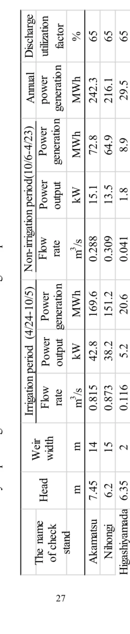
Table 3.1 shows that the overflow depth of spillway at check stands is managed as irrigation period +10 cm and non-irrigation period +5 cm. The power generation was calculated using overflow discharge which is calculated using Francis Formula and the height of difference between floor height of spillway and discharge destination. The discharge utilization factor in the table 3.1 is the value which obtained when the planned irrigation discharge in the irrigation period is assumed as the maximum flow rate. The annual power generation was estimated using parameters in Table 3.1, and it is large in the order of Akamatsu, Nihongi, and Higashiyamada. Furthermore, the power output is larger during the irrigation period when the target water level is managed as higher, and the power output is reduced during the non-irrigation period when the target water level is managed as lower. However, even if the power output during the irrigation period is
25
assumed to be the maximum power output, the discharge utilization factor is still higher value of 65%.
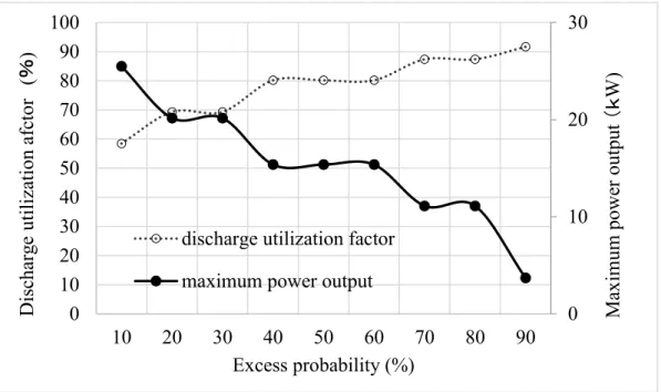
Next, the overflow discharge was calculated from the daily water level which was recorded at the check stands over the 20 years, and the relationship between the maximum power output and the discharge utilization factor, and the annual and monthly power generation was obtained. Fig. 3.8 shows the relationship between the discharge utilization factor and the maximum power output of Akamatsu stand, which has the largest power generation potential among three check stands. From Fig. 3.8, when the discharge utilization factor is 60%, the excess probability is 11.4%, which is smaller compared to 32.2% at the head work and 46.3% at the industrial diversion work. However, it meant that the fluctuation of overflow discharge is small. The maximum power output was 24.7kW when the discharge utilization factor is 60%, and the results of the annual power generation are shown in Fig. 3.9. The minimum value is 93.2MWh in 2001 and the maximum value is 188.1MWh in 2005. The average annual power generation for 20 years is 144.5MWh (Table 3.2), which is about 60% smaller than the annual power generation of 242.3MWh in Table 3.1. This is probably that the overflow depth of the spillway of check stand was managed as smallest as much as possible in order to use the water effectively in actual water management. Fig. 3.10 shows the average monthly power generation, 25%, and 75% of monthly power generation at Akamatsu check stand. The maximum value of average monthly power generation is 14.2 MWh in December during the non-irrigation period and the minimum value is 9.1 MWh in June during the irrigation period. This results shows the opposite trends to the Table 3.1. Monthly power generation at Akamatsu check stand was assumed to increase during the irrigation period same as industrial water division work (Fig. 3.7), but based on actual data in the calculation, power
26
generation tended to decrease during the irrigation period. This is thought to be that precise water delivery management is being carried out in order to reduce the excess water during the irrigation period at the Akamatsu check stand. On the other hand, both 25%, and 75% values of monthly power generation have small fluctuations through the year, average monthly power generation is about 10 MWh. It meant that stable power generation is possible. In addition, the delivery management water of Akamatsu Check stand flows into the Oida dirty water division, flowing through Anjo City which is expected to contribute to improving water quality in drainage channels during non-irrigation periods and to have the function of environmental water.
27
D
isc
ha
rg
e
ut
iliz
at
io
n
fa
ct
or
m
m
m
3/s
kW
M
W
h
m
3/s
kW
M
W
h
M
W
h
%
A
ka
m
at
su
7.4
5
14
0.8
15
42
.8
16
9.6
0.2
88
15
.1
72
.8
24
2.3
65
N
iho
ng
i
6.2
15
0.8
73
38
.2
15
1.2
0.3
09
13
.5
64
.9
21
6.1
65
H
iga
sh
iya
m
ad
a
6.3
5
2
0.1
16
5.2
20
.6
0.0
41
1.8
8.9
29
.5
65
H
ea
d
Irr
iga
tio
n p
er
io
d
(
4/
24
-1
0/
5)
N
on
-ir
rig
at
io
n p
er
io
d(
10
/6
-4
/2
3)
Th
e
na
m
e
of
c
he
ck
sta
nd
A
nn
ua
l
po
w
er
ge
ne
ra
tio
n
W
eir
w
id
th
Fl
ow rat
e
Po
w
er
ou
tp
ut
Pow
er
ge
ne
ra
tio
n
Fl
ow rat
e
Po
w
er
ou
tp
ut
Po
w
er
ge
ne
ra
tio
n
Tab
le 3.
1 Str
uc
tu
re p
aram
et
ers
, p
lan
o
f i
rri
gat
io
n m
an
ag
em
en
t a
nd
p
aram
et
ers
o
f
hy
dro
po
w
er
ge
nera
tio
n e
sti
m
at
ed
o
n
th
e
irri
gat
io
n
pl
an
a
t eac
h
ch
ec
k s
ta
nd
28
Fig. 3.8 Estimated maximum power output and utilization ratio at the Akamatsu check stand
Fig. 3.9 Annual power generation at the Akamatsu check stand 0 10 20 30 0 10 20 30 40 50 60 70 80 90 100 10 20 30 40 50 60 70 80 90 Excess probability (%) discharge utilization factor maximum power output
Disc ha rg e uti liz ati on afc tor (% ) Ma xim um powe r output (k W) 0 20 40 60 80 100 120 140 160 180 200 1997 1998 1999 2000 2001 2002 2003 2004 2005 2006 2007 2008 2009 2010 2011 2012 2013 2014 2015 2016 A nnua l pow er g ene ra tion (MW h)
29
Fig. 3.10 Monthly power generation at the Akamatsu check stand (black line: mean value, black dot: 25 and 75 percentiles)
3.1.4 Delivery management water at Nihongi and Higashiyamada check stands Using the same analytical method above, the power generation potential at Nihongi
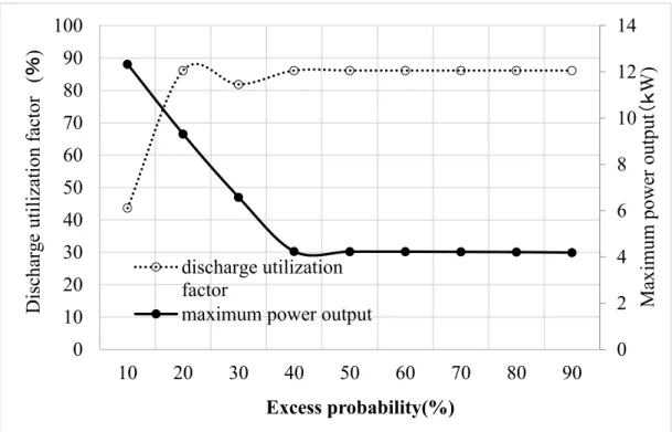
and Higashiyamada check stands was estimated. And both check stands have almost same tendency (Fig. 3.13 and Fig. 3.16) as the Akamatsu check stand. The maximum power output is 7.4 kW (Fig. 3.11) and annual average power generation is 38.4 MWh (Fig. 3.12) at Nihongi check stand. On the other hand, at Higashiyamada check stand, maximum power output is 6.5 (Fig. 3.14) and annual average power generation is 33.8 MWh (Fig. 3.15) when discharge utilization factor is 60%. In particular, Higashiyamada Check stand is located at the end of the Middle canal, and there is no beneficiary area in the downstream. Therefore, the water level of check stand was higher than the target water level due to residual water from the upstream of mainline waterway. The power generation is larger than the target value in Table 3.1. As same with Akamatsu Check
0 5 10 15 20
Jan Feb Mar Apr May Jun Jul Aug Sep Oct Nov Dec
Monthly pow er g ene ra tion (MW h)
30
stand, the maximum value of monthly power generation of both check stands occurred during the non-irrigation period and the minimum value during the irrigation period. In addition, the delivery management water in both check stands flows into the dirty water canal, which helps to improve the water quality of the drainage channel in the non-irrigation period.
Fig. 3.11 Estimated maximum power output and utilization ratio at the Nihongi check stand 0 2 4 6 8 10 12 14 0 10 20 30 40 50 60 70 80 90 100 10 20 30 40 50 60 70 80 90 Excess probability(%) discharge utilization factor
maximum power output
Disc ha rg e uti liz ati on fa ctor (% ) Ma xim um powe r output (k W)
31
Fig. 3.12 Annual power generation at the Nihongi check stand
Fig. 3.13 Monthly power generation at the Nihongi check stand (black line: mean value, black dot: 25 and 75 percentiles)
0 10 20 30 40 50 60 70 1997 1998 1999 2000 2001 2002 2003 2004 2005 2006 2007 2008 2009 2010 2011 2012 2013 2014 2015 2016 Annua l powe r g ene ra tion (MW h) 0 1 2 3 4 5 6 7
Jan Feb Mar Apr May Jun Jul Aug Sep Oct Nov Dec
Mont hly powe r g ene ra tion (MW h)
32
Fig. 3.14 Estimated maximum power output and utilization ratio at the Higashiyamada check stand
Fig 3.15 Annual power generation at the Higashiyamada check stand 0 2 4 6 8 10 12 0 10 20 30 40 50 60 70 80 90 100 10 20 30 40 50 60 70 80 90 Excess probability (%)
discharge utilization factor maximum power output
Disc ha rg e uti liz ati on fa ctor (% ) Ma xim um powe r output (k W) 0 5 10 15 20 25 30 35 40 45 50 1997 1998 1999 2000 2001 2002 2003 2004 2005 2006 2007 2008 2009 2010 2011 2012 2013 2014 2015 2016 Annua l powe r g ene ra tion (MW h)
33
Fig 3.16 Monthly power generation at the Higashiyamada check stand (black line: mean value, black dot: 25 and 75 percentiles)
3.1.5 The generation potential at mud drainage works
The Hirokute water control gate is located at the end of the open channel of Meiji-yousui mainline waterway, and it divides water into the Western canal at this place. Chuto division work is placed at the end of Meiji-yousui mainline waterway, from this point the downstream is branched into Eastern canal and Middle canal. Therefore, in order to avoid the sediment mixed with the water from the upstream into the Western canal, Eastern canal and Middle canal, Sawatari mud drainage work which is placed at the upstream of Western canal and Matsushita mud drainage work which is placed at the upstream of Chuto division work were constructed. Sawatari mud drainage work is capable of flowing a maximum flow rate of 1.0m3/s as a discharge for drainage, and the head is obtained
from the difference of the water level of Hirokute water control gate (27.5m for the irrigation period, 27.0m for the non-irrigation period) and the bottom of the drainage pipe
0 1 2 3 4 5
Jan Feb Mar Apr May Jun Jul Aug Sep Oct Nov Dec
Mont hly powe r g ene ra tion (MW h)
34
of 18.5m. So the difference value is 8.5-9.0m. The possible power output is 60.0-63.5kW. On the other hand, Matsushita mud drainage work has the function of available to discharge a maximum flow rate of 0.3m3/s as discharge for drainage, and the head is
difference value of the target water level (elevation: 27.0m) of the Chuto division work and the tube bottom of mud drainage gate (elevation:19.25) and which is 7.75m. The possible power output is 16.4kW.
In this way, both mud drainage works have a flow rate and a head with the maximum power output equal to or higher than that of the check stands. Furthermore, the drainage of the Sawatari mud drainage work will be flown down to Kinuura Bay via the second-class river Sawatari River, and the drainage of the Matsushita drainage work will be flown into to the first-class river Kanori via the Matsushita dirty water channel and the Oita River. At present, the drainage water at these two mud drainage works is not secured as a facility maintenance water, and the drainage is concentrated twice a year, but, if continuous water flow is realized, the power generation potential described above can be available, and it can be expected to improve the water quality of drainage channel and rivers, especially during the non-irrigation period.
3.1.6 The comparison of research sites
Table 3.2 summarized the results at each research place when the discharge utilization factor is assumed to be 60%. Here, if the discharge utilization factor is assumed higher, the maximum power output, annual power generation, monthly power generation, the ratio of standard deviation and average value, and ratio of maximum value to minimum value becomes smaller, but the magnitude relationship between each research place does not change.
35
The maximum power output, the average annual power generation, and the maximum monthly power generation are biggest at the Meiji-yousui headwork, followed by industrial water division work, Akamatsu check stand, Nihongi check stand, and Higashiyamada check stand. The ratio between the standard deviation and the average value of annual power generation showed a value of around 0.20 for the headwork and check stands, while, the agricultural water-dependent type of power generation at industrial division site is the smallest as 0.05, whichshowed that stable power generation is possible every year. On the other hand, the ratio between the maximum and minimum monthly power generation was 7.0 at industrial water diversion work, and compared to this, the values at the headwork and check stands are from 1.46 to 2.12. It showed the stable power generation is possible every year at the headwork and check stands.
36
kW
941
60
.4
24
.7
7.
4
6.
5
A
ve
ra
ge
va
lue
:①
M
W
h/
Y
4,9
44
293
14
4.
5
38
.4
33
.8
St
an
da
rd
de
via
tio
n:②
M
W
h/
Y
944
14
.8
28
.4
9.
1
7.
9
Ra
tio
:②
/①
0.
19
0.
05
0.
19
0.
23
0.
23
M
ax
im
um
va
lue
:①
M
W
h/
M
571
(
O
ct
)
44
.9
(
Ju
l)
14
.2
(
D
ec
)
3.
9
(
A
pr
)
3.
6
(
O
ct
)
M
ini
m
um
va
lue
:②
M
W
h/
M
312
(
Ju
n)
6.
4
(
N
ov
)
9.
1
(
Ju
n)
2.
6
(
Ju
n)
1.
7
(
A
ug
)
Ra
tio
:①
/②
1.
83
7.
0
1.
56
1.
46
2.
12
M
ax
im
um
p
ow
er
ou
tp
ut
M
eij
i Y
ou
su
i
he
ad
w
ork
In
du
stri
al
div
isi
on
w
ork
A
ka
m
at
su
N
iho
ng
i
H
iga
sh
iya
m
ad
a
Ch
ec
k s
ta
nd
A
nn
ua
l
po
w
er
ge
ne
ra
tio
n
M
on
th
ly
po
w
er
ge
ne
ra
tio
n
D
im
en
sio
nle
ss
D
im
en
sio
nle
ss
Po
w
er
ge
ne
ra
tio
n
sit
es
Po
w
er
ge
ne
ra
tio
n
Tab
le 3.
2
Max
im
um
po
w
er
ou
tp
ut
a
nd
a
nn
ual
an
d m
on
th
ly
p
ow
er
ge
nera
tio
n at e
ac
h pote
nt
ia
l
po
w
er
pl
an
t s
ite
37
3.1.7 Conclusion
Small hydropower generation at the Meiji-yousui headwork site has annual and monthly fluctuations, but the power generation potential is large at this site, and the maximum power output is 941kW with discharge utilization factor of 60%. Considering the actual operation, although there is an argument about using the weir height of 5.6m as an effective head for power generation, if a water conduit is provided further downstream from the headwork, it is possible to secure the same level of the head mentioned above. Furthermore, if the maximum power output becomes lower, the discharge utilization factor is expected to increase, and the reduction of the project cost and the improvement of cost-effectiveness can be expected by reducing the equipment scale. However, because of not an agricultural water-dependent type of power generation, a new procedure for acquiring water rights for power generation is required, and since a power generation facility is installed in the river channel, permission from the river manager based on the River Law is required. For this reason, the actual installation cases of small hydropower generation in river channels at the headwork are very few, such as the Arashiyama Small Hydroelectric Power Station (Ministry of Land, Infrastructure, Transport and Tourism, 2016) using the head of the Ichinoi weir in the Katsuragawa which is branch river of Yodogawa. Although there are few actual installation examples, from this analysis, the power generation potential is large at headwork and future progress can be expected.
Agriculture water dependent type of power generation is possible at the industrial water division work, and it is easy to commercialize. However, power generation has fluctuation during the irrigation and non-irrigation periods, and, fluctuation of annual power generation is small and stable power generation is possible every year. At present,
38
at an industrial division site in Middle canal is being investigated for the installation of small hydropower generation facility with a flow rate of 0.96m3 / s, an effective head of
6m, a maximum output of 38kW, and a utilization rate of 85.2%.
On the other hand, delivery management water at check stands is generated throughout the year as for functional maintenance water for facilities, so it is possible to generate electricity with a high discharge utilization factor, although it is small scale compared to agricultural water dependent type of power generation. Moreover, since overflow discharge from the spillway flows down to the drainage channel outside the district, it is possible to secure a higher head with a small flow rate, and it is possible to make a higher efficient power generation. Furthermore, after generating the electricity, the delivery management water flows into the drainage channel outside the district, and it contributes to improving the water quality of the drainage channel, especially in the non-irrigation period and also it has the functions as environmental water. In this analysis, the estimated power generation by delivery management water at Akamatsu and Nihongi checkstand shown in Table 3.2 is smaller than the planned value shown in Table 3.1, but if these delivery management water are used more actively, the power generation will be improved. In addition, the delivery management water at Nihongi and Higashiyamada check stands is flown through the industrial division work in Middle canal which has power generation potential, so that more efficient repeated power generation is possible. Like the check stands, the two mud drainage works also have power generation potential. They have flow rates and heads. However, because there is no water right as facility maintenance water, it is in the current situation, flow rate is not stable.
39
3.2 Potential for and feasibility of small hydropower generation at headworks in Japan
3.2.1 Daily overflow discharge and excess probability
Fig. 3.17 shows the flow duration curves which express the relation between the
overflow discharge at the headworks and the excess probability. In this case, the excess
probability is expressed as a percentage by rearranging the daily overflow discharge in descending order and dividing the number of days exceeding a certain discharge by the number of days during the observation period.
The three standard discharges can be defined as rich discharge (three-month flow), ordinary discharge (six-month flow) and low discharge (nine-month flow) from the excess probabilities of 25, 50 and 75%, respectively.
Table 3.3 shows the three standard amounts of overflow discharge at each headwork. It can be seen that the overflow discharge amounts of all three standards at IY are the largest. The rich water discharge and the ordinary water discharge are the second largest at MJ followed by MM, HK, KS, OK, ON and FK. The low water discharge is the second largest at MM followed by MJ, HK, OK, KS, ON and FK.
The fluctuation rate of the overflow discharge is defined by the following equation: Fluctuation rate =𝑅𝑖𝑐ℎ 𝑤𝑎𝑡𝑒𝑟 𝑑𝑖𝑠𝑐ℎ𝑎𝑟𝑔𝑒 − 𝐿𝑜𝑤 𝑤𝑎𝑡𝑒𝑟 𝑑𝑖𝑠𝑐ℎ𝑎𝑟𝑔𝑒
𝑂𝑟𝑑𝑖𝑛𝑎𝑟𝑦 𝑤𝑎𝑡𝑒𝑟 𝑑𝑖𝑠𝑐ℎ𝑎𝑟𝑔𝑒
The fluctuation rate is the smallest at IY, followed by the rates at OK, ON and FK, which are equal to or less than 1.0, respectively, and showed the discharge to be stable compared to the other headworks. The amounts of overflow discharge at these four headworks are more stable than the others. This is because there are beneficiary areas in the downstream of IY, ON and FK headworks and there are two dams (Yokoyama Dam and Tokuyama Dam) in which the river flow is controlled in the upstream of OK
40
headwork. However, the impact is not significant due to the dams in the upstream.
Fig. 3.17 Distribution curves of amounts of overflow discharge at headworks
0
1
10
100
1,000
0
10 20 30 40 50 60 70 80 90 100
O
verfl
ow
d
isch
ar
ge
(m
³/s
)
Excess probability (%)
IY MJ MM KS FK ON HK OK41
Table 3.3 Amounts of overflow discharge at test headworks
3.2.2 Maximum power output with discharge utilization factor of 60%
Fig. 3.18 shows the relation between the excess probability and the discharge utilization factor, and Fig. 3.19 shows the relation between the excess probability and the maximum power output.
The maximum power output with the discharge utilization factor of 60% at each headwork is determined by the following two steps.
Firstly, the excess probability of the overflow discharge, corresponding to the discharge utilization factor of 60%, is obtained by Fig. 3.18, which varies from 18.2% (OK) to 32.0% (MJ).
Secondly, the maximum power output corresponding to each excess probability of discharge utilization factor (60%) is obtained by Fig. 3.19, which widely ranges from 43 kW (FK) to 2,002 kW (IY). The results are summarized in Table 3.4.
However, even if the maximum power output shown in Table 3.4 is adopted, the
IY
44.5
34.5
20.5
0.70
MJ
29.1
14.3
6.4
1.59
MM
18.9
10.1
6.9
1.19
KS
6.4
3.5
1.8
1.31
FK
2.3
1.4
0.9
1.00
ON
3.3
2.3
1.3
0.87
HK
11.6
6.4
2.7
1.39
OK
5.0
3.3
2.3
0.82
Headwork Rich water
discharge
(m³/s)
Ordinary water
discharge
(m³/s)
Low water
discharge
(m³/s)
①
②
③
④
Fluctuation
rate
(①-③)/②
42
discharge utilization factor will become less than 60% when unexpected droughts with more than a 21-year return period occur.
Fig. 3.18 Excess probability and discharge utilization factor